Dragon Sdkfz 138/1 Geschutzwagen 38 H fur sIG 33/1 (Grille H) (2009)

Bill Plunk
Posts: 1245
Joined: Wed Sep 28, 2022 10:18 pm

WIP 04-11-2009

Post by Bill Plunk »

I had finally decided after looking at reference photos that I was going to add the missing tread plate that the gun crew would've used as a platform. The tread plate can be clearly seen in both the MBI and Spielberger photos.

MBI:
Image

Spielberger:

Image

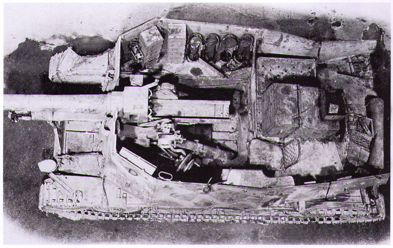
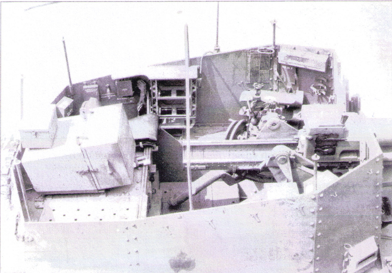
In both photos you can see that the tread plate sits fairly high inside the lower hull, roughly flush with the curve over the bulkhead to the engine compartment on the MBI photo and about level with the drive shaft in the Speilberger photo. The Spielberger photo seems to have the simplified I-beam style of mount vs. the stepped style mount in the MBI photo, hence DML's option of mount types. I had used the stepped style so, in preparation for adding the tread plate, I did a dry fit of the gun mount and gun to see how things would line up using some poster blue tack to hold things in place.

Image

I immediately noticed that something was wrong...the bases of the equilibrators were much lower than shown in either the
MBI or Spielberger photos. I compared the angles in the H mount vs. those in the M and it would appear that DML copied the angles from their earlier released M kit and didn't bother changing them for the H style mount which has a shallower angle configuration. This, to me, explains why there's no raised tread plate platform...if DML had included it, they would've had to change the angles on the equilibrators which would've required a totally new gun mount sprue. Instead, they stuck with the M style and omitted the plate. It also means that my plan to add the missing tread plate is now scrapped as it's impossible to change the angle on the equilibrators without completely replacing them due to the way they are integrated into the sides of the gun mount. That means I can't locate the plate at the correct height/level and throws everything off from an accuracy perspective and represents a substantial error on the interior IMHO.
Bill Plunk
Posts: 1245
Joined: Wed Sep 28, 2022 10:18 pm

WIP 04-12-2009

Post by Bill Plunk »

Today was a very productive Easter Sunday although I will admit that some of the work in this update was actually accomplished yesterday!

In looking into the problem with the gun mount and the equilibrators, I came across a detail that Gary Edmundson had included in his build in the Osprey "Modelling the German 15cm Bison and Grille". That detail is the inclusion of two additional round racks in the floor area ahead of the rifle racks. This item doesn't show up in any of the interior photos in MBI and Spielberger because of angles but Gary mentions he used photos of a Grille recovered in Austria from the river Enns so I'm guessing that's where he got it from. It's not something mentioned in the DML instructions but additional ammo racks are available on the sprues, so I painted 2 up and stuck them into position. It makes sense to me that this space would be used for this since there's no radio operator and it's just dead space otherwise.

Image

Returning to the left side, I installed the missing MP40 after test fits with the lower hull to get it in the correct position. The gunner's seat was also added and I scrounged a firing table decal from an unused set from the Bronco Marder I that I trimmed down to size and applied with Solvaset. Some weathering was added in the form of some Burnt Umber stippled in place for some scuff marks and then counter-stippled with the base coat color to break it up and provide some randomness. A pin wash of Raw Umber was also applied and then the base coat dry brushed over that to blend it back in where needed. A spray coat of Testors Lusterless Flat was applied to seal it all in prior to installation.

Image

The same process was also applied to the right side.

Image

I also assembled and installed the radio operator's chair and began the assembly of the fighting compartment. First up was the installation of the front plate. In order to achieve that, the gun travel lock needed to be installed and mated up with the latch on the interior through the little key-hole opening in the front plate. Once that had dried, I glued the front plate down with liquid glue and let it set up. I finally figured out what the pre-bent piece of steel wire that was provided as part MC-2 was for...it's supposed to represent the wiring conduit for the Notek light. I wrestled with it for a while trying to get it to fit into the proper position and finally gave up. Reference photos show it's supposed to hug the joint between the glacis and the superstructure front plate but the wire's too big for that to actually happen, so I left it off.

Image

Now came the moment of truth, time to add the superstructure sides and the rear doors and central panel to create the fighting compartment. After much thought, I decided to mount the tools later as I'm worried that there's not enough clearance at the front for example to mount the wire cutters and sledge hammer as called for in the instructions. Rather than have them possibly interfere with the compartment sides, it was more important that they fit properly first and I'll worry about the tools later. Due to the way the end curved brace has to fit under the engine access hatches, it has to be slid into position first since it fits sort of like in a groove and then the sides slid into position. Can't do that if the tools or gear on the rear portions of the fenders are installed, so that too will come later. I added the left hand side first with regular glue for the joins along the sides and once that had started to set I used liquid glue and finger pressure for the joint with the front plate. The same process was then repeated with the right side and when both sides were solid, I added the hinge points and installed the rear doors and center panel. A very small amount of putty was needed at the join on the front right side near the base but otherwise everything went together smoothly.

Image

Image

Completing the effort for today, I detailed the gun breech using enamel Silver for the interior of the breech and the sliding block. The activation handle was painted with non-buffing metalizer Gunmetal and then dry brushed with steel as were the elevation wheels. The gun sight was also detailed and the eye piece drilled out with a pin vise. The interior portions of the gun were given a wash of Raw Umber and then dry brushed with the base coat. The contact rails for the recoil sled were painted with Steel for their bare metal look to round things out. The rest of the gun will be weathered along with the exterior when the time comes after it's been installed.

Image

Total Session Time: 7.25 hours

Total Time to Date: 45.5 hours
Bill Plunk
Posts: 1245
Joined: Wed Sep 28, 2022 10:18 pm

WIP 04-13-2009

Post by Bill Plunk »

I had the day off today as part of an extended Easter weekend so decided to make the most of it. I added the missing details to the superstructure in the form of the antenna mount and base as well as the lower PE loops for the foul weather gear. The PE fret includes almost 2 full sets of loops so there's plenty of extras in case you lose some along the way. I added the loops using the reference photos in MBI since the kit instructions are somewhat vague on their actual placement. The loops were installed using a combination of CA gel applied to the PE parts as well as a small amount of liquid glue to the superstructure panel to insure a good solid join and also provide some flexibility/work-time although not much. I opted to leave the molded on top rectangular loops though as the PE items were too fragile and easily damaged when trying to remove them from the fret.

With that out of the way, I masked off the interior with blue painter's tape and it was off to the garage for some time with the airbrush.

Image

I repeated the previous painting process for the interior, laying down a primer coat of Italian Dark Brown followed by a 50-50 base coat of Dunkelgelb/Light Gray. I decided to apply the camo pattern for a LAH vehicle at Kursk '43 and used Khaki for the olivegrun pattern. I sprayed the cross-hatched/web pattern free hand, starting on the left hand side and working my way around the superstructure, deliberately leaving the fenders out of the pattern. A light mist coat of the base coat mix was then sprayed back over it to tie everything together and provide a foundation for the weathering process.

Image

Image

The road wheels and return rollers were also detailed, their rubber portions were sprayed using Gunmetal and the hubs sprayed with the base coat mix using a circle template.

Image

Total Session Time: 4.5 hours

Total Time to Date: 50.0 hours
Bill Plunk
Posts: 1245
Joined: Wed Sep 28, 2022 10:18 pm

WIP 04-18-2009

Post by Bill Plunk »

Getting much closer to the finish line now and the latest round of effort focused in on the details for the exterior. The astute observer from the previous post will have noticed that I only painted 7 of the 8 road wheels...a fact I discovered when I went to test fit them in today's efforts and came up 1 short. Fortunately I found the wheel out in the garage where I do my painting and disaster was averted. I painted the wheel and also went back over the camo pattern and removed the green over spray to make the dunkelgelb color a little more dominant than it was before.

I also stated in on the tools and other equipment for the fenders. Starting on the left side, I already knew that the kit suggested positioning of the shovel and pick axe weren't going to work. The diagram wants you to install the shovel flat against the vertical side of the engine access hatch but you can't do that due to the interference from the curved rear brace of the fighting compartment side. The diagram suggestion is how these were configured on the 38t gun-tank and is a hold-over from their 38t G instruction diagrams. The solution is to position the shovel flat on the fender and have the pick axe sit on top of it. In order to be able to handle this as one piece instead of two, I used some liquid glue and glued the handles of the shovel and pick together in position and let it dry. I also test fit the location of the long pry bar to be sure it too would go in the right spot.

Image

With that out of the way, I painted up all the tools for installation with the exception of the wire cutters, more on them in a bit. All of the wood portions were painted with an 80/20 mix of Afrika Grunbraun and Light Gray and then given a light wash of Leather. The metallic portions were painted with non-buffing Metalizer Gunmetal and then lightly dry-brushed with Steel. I added the PE retaining straps to the axe and pick/shovel as well as the pry bar but left it off the sledge hammer since it won't be visible once installed and would've caused clearance problems with the superstructure when sliding it into place.

I'm not too impressed with the DML PE in this department...all of the straps provided are the same and fairly plain and lacking in detail. They also don't have any bend lines to help guide you in sizing them so you have to do it all by trial and error and even then they are too short for some of the things the instructions call for them to do. For example, they are too short to tie the shovel and pick together and also too short to adequately go around the wire cutters. This means you have to cheat a bit and position the gaps so that they are on the inside and away from view.

Image

I installed the tools on the left hand side once they had dried and the wire cutters required special attention. The clearance at the front of the superstructure is insufficient to allow the inside handle to clear it properly. Since it's hidden from view anyway, I carefully trimmed it down to only that portion that would be visible and still allow it to fit. The road wheels and return rollers were also installed in anticipation of the tracks getting fitted tomorrow.

Image

I also worked on the rear hull details. The muffler was base coated with non-buffing Metalizer Gunmetal and given a wash of Rust and the spare track run added to the rear superstructure plate. The lenses of the Notek were picked out with Tamiya Clear Green and the four small leather straps added to the rear crew doors. I also added the 3 retaining PE straps for the tow cable and noticed on sprue A that two cable ends were included in the kit as parts A27. These aren't called out anywhere in the instructions and the front diagrams don't have them marked as not for use so they are a sort of "Easter egg" for you to find if you're vigilant I guess. I created the cable using a 10cm length of crochet rope that I first dipped into Future and hung to air dry. This accomplishes two things...it insures the rope won't fray and get "hairy" when painted and also stiffens it up a bit but not too much that it still can't be shaped into the proper position. The cable was painted up with the same metalizer Gunmetal and then installed into position and the leather straps glued into place to hold it down. In hindsight I could have benefited from having the thread just a few mm longer but had to kind of wing it in terms of overall length since no guidance is provided in the instructions.

Image

The right side received its share of attention as well. The jack block was installed along with the two spare track runs at the front and rear of the fender. The sledge was glued into place and the head can be seen poking out towards the rear but that's it, the rest is hidden from view. The axe does a similar disappearing act at the front of the fender.

Image

Last but not least, the spare track run of 7 links was added to the glacis and its retainer bar glued into place. I didn't notice until this pic that I hadn't painted the leather straps on the jack, will take care of that with tomorrow's activity.

Image

Next up will be weathering the lower hull and getting the tracks on!

Total Session Time: 6.5 hours

Total Time to Date: 56.5 hours
Bill Plunk
Posts: 1245
Joined: Wed Sep 28, 2022 10:18 pm

WIP 04-19-2009

Post by Bill Plunk »

Today's efforts turned out to more of an endurance challenge than I first anticipated. Things got off to an easy enough start with the final installation of the sIG 33 and mount into the hull. I added the hinged armored piece as well to round things out in that department. In anticipation of adding the tracks I also added some light scuffing/weathering to the lower hull and road wheels by stippling some Burnt Umber with a round sable brush.

Image

Next up were the magic tracks. The kit instructions call for 96 per side but that's way too many. Normally the 38t family need about 92 links per side so I cleaned up 184 links, removing the small ejector marks and the small scar in the middle from where they were once attached to a sprue. Some of the links also had some minor flash on the guide horns, so that was also removed as required. My assembly process for indy links is pretty simple...I assemble them 5 at a time as that seems to be about what works until the glue has a chance to set. I use regular Testors Model Master glue in the black bottle and will daisy-chain the groups of 5 together once I've got three built with the first and second getting added together while the third sets up a bit and I assemble the fourth. Once the fourth is assembled, the third gets added to the run and so on. As each group of 5 gets added, I use a pair of metal rulers to press down on the run using the guide horns to keep everything straight. I assembled two runs, one of 23 links for the lower and one of 70 for the upper to give a total of 93.

Image

My next step is a little unorthodox but is a method that works well for my needs...I paint the runs while the glue is still setting up. The runs were brush painted with non-buffing Metalizer Gunmetal which dries very quickly since it's lacquer-based. I wear a paint breather mask as the fumes can be pretty strong even with good circulation. The runs are then dry brushed with Steel and given a quick wash of enamel Raw Umber to blend the Steel in and give it a used look. As soon as the wash dries, the runs get installed. I built and installed the right hand side first using a pair of toothpicks to help produce the right amount of sag. Turned out that in order to have the idler sit properly level with the last road wheel, only 90 links were required.

Image

In order to insure a nice level set while the track is drying, I built the left hand side of 23 links and placed it under the left side while I worked on the rest of the links for that side.

Image

The process was then repeated, installing the left hand side also with 90 links.

Image

The tracks will set up overnight and then the toothpicks will be removed. There are a few odds and ends in the detail department for me to take care of and then it will be on to the decals and weathering stage.

Total Session Time: 7.5 hours

Total Time to Date: 64.0 hours
Bill Plunk
Posts: 1245
Joined: Wed Sep 28, 2022 10:18 pm

WIP 04-26-2009

Post by Bill Plunk »

Originally I had thought that I would get everything completed this weekend on this particular project but, as it turned out, I didn't quite make it as far as I'd hoped. The first order of business was to add the last detail in the form of the radio antenna and get it painted up and installed. I applied a sealing coat of Future by airbrush and let it thoroughly dry for 1 hour before applying the kit-supplied decal markings. The markings were treated with Solvset and then a second sealing coat of Future applied. The second coat was allowed to cure overnight before the weathering process began. The markings were pretty straightforward, just the balkenkreuze on the superstructure sides and hull rear along with the LAH insignia front and back.

Image

Image

The first step was to apply an overall light wash of enamel Raw Umber using a #1 round sable brush.

Image

That laid the foundation for the next round, the application of dot filters. The arsenal for that consisting of enamel Panzer Olivegrun, Deep Yellow, Flat White, and Military Brown, and a mixing bottle of clean thinner.

Image

The first dot filter used the Olivegrun, Deep Yellow, and Flat White to introduce some color variation and fading to the underlying paint scheme. Small dots of paint were applied in sections, working slowly around the vehicle one section at a time, and the dots blended in and away with a flat tipped brush dampened with clean thinner.

Image

This was followed by the second dot filter using the Military Brown. This was applied with fewer dots and the initial blending done the same way as with the previous filter. To introduce/simulate dust/dirt streaking due to rain and prolonged exposure, I turned the flat tip brush 90 degrees and used repeated strokes to produce the desired amount of streaking.

Because all of this work involves working with thinner, I wore a paint breather mask the entire time even with the excellent air circulation at my work bench as a standard precaution.

Image

Once that was complete, a pin wash of enamel Burnt Umber was applied to all the raised detail using a pointed 3/10 brush. Excess wash was carefully removed using the same brush and clean thinner to tighten things up. The Burnt Umber was was also applied to the road wheels and running gear in anticipation of the application of pigments, something that was scheduled for today but I didn't quite get to.

Image

I will let this sit for a few days and then come back to it with a fresh set of eyes to evaluate if additional adjustments are needed before sealing it up with a flat coat and starting in on the final pigment weathering.

Total Session Time: 7.25 hours

Total Time to Date: 71.25 hours
Bill Plunk
Posts: 1245
Joined: Wed Sep 28, 2022 10:18 pm

WIP 05-02-2009

Post by Bill Plunk »

Picking up from where I left off last week, I made a few minor adjustments here and there in the previous pin wash work and decided that a little something more was called for. Given the fact that the fighting compartment sides extend right to the edge of the fenders, I decided to add some slight scratching to the previous weathering. To do this, I used the 50-50 dunkelgelb/light gray mix from before and an 18/0 Script brush to add in the marks where desired. I followed this up with a slightly dampened square tip blender brush and carefully worked the scratching into the rest of the finish on both sides.

Image

Image

The next step was to seal everything in with an overall coat of Testors Lusterless Flat lacquer in the spray can. This was left to thoroughly dry for an hour or so before starting in on the pigment weathering.

Image

I mixed up a batch of 50-50 Mig Dark Mud and Europe Dust pigments as a dry powder in an old prescription bottle lid until they were thoroughly combined. Water was added to create a wet mixture and the mixture then applied to the lower hull, running gear, and tracks with a round 0 sable brush and allowed to air dry. After an hour or so, I donned a sanding/dust mask (reminded me of the H1N1 footage on TV!) to avoid inhaling pigment dust and began the fine-tuning process by removing the excess pigment using a square tipped stiff bristled brush.

Image

Image

The next step involved the removal of even more pigment, this time using a Q-tip moistened with water. This allows for a more strategic removal and blending process along with a dry Q-tip end to get a varied look to the pigment application. The Dark Mud is a powerful pigment, capable of staining all by itself and is the main reason I pair it up with the lighter Europe Dust pigment to prevent a too-dark end result. The Q-tip treatment is applied to all the road wheels, sprockets, idlers, and return rollers as well as the track faces themselves.

Image

Image

The final touch was a light dry brushing of Steel to bring out some of the contact points on the guide horns and track faces.

Image

Image

Tomorrow I'll do the walk-around photo inspection to see if there's anything else I missed or need to adjust before this one is marked down as complete.

Total Session Time: 4.25 hours

Total Time to Date: 75.50 hours
Bill Plunk
Posts: 1245
Joined: Wed Sep 28, 2022 10:18 pm

Completion 05-03-2009

Post by Bill Plunk »

After a short stint in the photo booth, this one is now done. Build #95 is in the bag!

Image

Image

Image

Image

Image

Image
Bill Plunk
Posts: 1245
Joined: Wed Sep 28, 2022 10:18 pm

Re: Dragon Sdkfz 138/1 Geschutzwagen 38 H fur sIG 33/1 (Grille H) (2009)

Post by Bill Plunk »

This build is featured in the FineScale Modeler Dec 2022 DLC Issue

Image
Post Reply