
Dragon Sdkfz 186 JagdTiger Henschel Production Type (2008)
-
Bill Plunk
- Posts: 1245
- Joined: Wed Sep 28, 2022 10:18 pm
Dragon Sdkfz 186 JagdTiger Henschel Production Type (2008)
Build log for Dragon kit # 6285 combined with ModelKasten SK-21 replacement tracks and Armorscale aluminum barrel and resin mantlet.
-
Bill Plunk
- Posts: 1245
- Joined: Wed Sep 28, 2022 10:18 pm
WIP 05-08-2008
After the Bison Bashing effort, I decided to tackle something a little simpler and pulled out DML's Jagdtiger from the stash. This particular build project will be mostly OOB with the exception of the MK tracks and Armorscale barrel. The kit comes with an aluminum barrel but it lacks rifling, and for a gun of this size at 12.8 cm, it's noticeable. The kit provides Magic Tracks but I wanted workables since I also have decided to leave off the side skirts altogether.
So, to start with Step 1, the first thing that needed modification were the sprockets and idlers with parts included in the MK set. These modifications allow for the sprockets to be freely rotating vs. fixed and the idlers to both freely rotate and be positionable on the mount arm for track tensioning, a valuable addition later on. For the sprockets, it was necessary to remove a semi-circular pour plug from inside the outer half to allow for clearance of the added MK part. This was no easy task as the plug was roughly half the height of the part itself, so a combination of sprue cutters and careful knife work as well as using a circular needle file had to be employed. As an older kit, there was also some minor flash that needed to be removed, particular on the inner spoke surfaces.

The idlers were a little easier to work with. Their modification required parts on the inside to allow it to rotate freely as well as a small piece added to the mount arm that inserts into the hull directly. The small added piece increases the diameter just enough to make it a tight friction fit and allow the idler arm to be moved and still hold its position.

With that out of the way, the rest of Step 1 was completed by removing the 18 road wheels from the sprues and removing their mold seam with a sanding board one by one. The wheels were then glued into pairs along with the now assembled sprockets and idlers. The sprockets had a small gap on their inner surfaces where the two halves were joined, this was filled with putty and sanded down carefully with a sanding twig.

Step 2 calls for the installation of the front side hull points for the final drive mounts as well as all the suspension arms. The hull points had a small gap where they meet up with the hull nose plate, this was filled with putty and sanded down. The suspension arms were installed and all the road wheels dry fit to insure a level set. I left the vehicle on a level surface overnight to insure a nice solid fit before moving on to the next steps.

Step 3 calls for the installation of the road wheels along with the final drive mounts and idlers and Step 4 installs the hub ends to secure the wheels in place. The sprocket and idler are not glued in place at this point, only dry fit to insure proper alignment and will be pulled off for painting before final installation. The road wheels are rotatable and the hubs were such a tight friction fit that no glue was necessary to get them into position, although a little bit of strategic pressure was called for on some arms.

Step 5 deals with the rear hull plate and its details. I left off the jack block and the towing clevises as those will be detailed and installed later. The exhausts are each a two-part assembly and the resulting seam was sanded down before the exhausts were installed. Their fit is a little loose to the cut-outs in the rear plate, so I had to exercise care to insure they were truly vertical.
Step 6 then installs the plate to the hull. The lower join had a prominent gap that required putty and sanding to fill.

Step 7 deals with the construction of the jack, which had three very prominent ejector marks on one side that needed putty and sanding. The "foot" of the jack also had an ejector mark in the center that received the same treatment. The jack was installed into its brackets and two pieces of PE marked as not for use on the fret, MA5, were used to close the brackets vs. just stay open. The armored exhaust covers were also installed along with the rear fenders. The right side fender slipped out of alignment just a bit but was corrected after taking this photo with some liquid glue and finger pressure.

Step 8 deals with the rear superstructure plate. I decided to keep the hatches closed and didn't bother with the interior parts of the hatches. They had ejector marks on the interior surfaces and the latch details also had marks that would've been a challenge to deal with, so I saved a bit of time by just closing them up. The holes for the grab handles are over-sized as you can see in this photo, they were filled with putty once the handles had set up.

Step 9 calls for the installation of the rear plate to the superstructure/upper hull. The fit is pretty good, only some small sanding was necessary on the "ears" for the side plates to achieve a smooth finish. The lifting eyes on the rear engine deck were also installed, the instructions here have 2 errors, parts D12 are really B12 and D20 is really B20. The right side hull details were also added and some molded on locator marks that aren't used were carefully scraped off with a #11 blade and lightly sanded. The spare track hooks are an exercise in patience to install and align properly, I used a link from the MK set to help insure they were level and lined up, working one set at a time.

So, to start with Step 1, the first thing that needed modification were the sprockets and idlers with parts included in the MK set. These modifications allow for the sprockets to be freely rotating vs. fixed and the idlers to both freely rotate and be positionable on the mount arm for track tensioning, a valuable addition later on. For the sprockets, it was necessary to remove a semi-circular pour plug from inside the outer half to allow for clearance of the added MK part. This was no easy task as the plug was roughly half the height of the part itself, so a combination of sprue cutters and careful knife work as well as using a circular needle file had to be employed. As an older kit, there was also some minor flash that needed to be removed, particular on the inner spoke surfaces.
The idlers were a little easier to work with. Their modification required parts on the inside to allow it to rotate freely as well as a small piece added to the mount arm that inserts into the hull directly. The small added piece increases the diameter just enough to make it a tight friction fit and allow the idler arm to be moved and still hold its position.
With that out of the way, the rest of Step 1 was completed by removing the 18 road wheels from the sprues and removing their mold seam with a sanding board one by one. The wheels were then glued into pairs along with the now assembled sprockets and idlers. The sprockets had a small gap on their inner surfaces where the two halves were joined, this was filled with putty and sanded down carefully with a sanding twig.
Step 2 calls for the installation of the front side hull points for the final drive mounts as well as all the suspension arms. The hull points had a small gap where they meet up with the hull nose plate, this was filled with putty and sanded down. The suspension arms were installed and all the road wheels dry fit to insure a level set. I left the vehicle on a level surface overnight to insure a nice solid fit before moving on to the next steps.
Step 3 calls for the installation of the road wheels along with the final drive mounts and idlers and Step 4 installs the hub ends to secure the wheels in place. The sprocket and idler are not glued in place at this point, only dry fit to insure proper alignment and will be pulled off for painting before final installation. The road wheels are rotatable and the hubs were such a tight friction fit that no glue was necessary to get them into position, although a little bit of strategic pressure was called for on some arms.
Step 5 deals with the rear hull plate and its details. I left off the jack block and the towing clevises as those will be detailed and installed later. The exhausts are each a two-part assembly and the resulting seam was sanded down before the exhausts were installed. Their fit is a little loose to the cut-outs in the rear plate, so I had to exercise care to insure they were truly vertical.
Step 6 then installs the plate to the hull. The lower join had a prominent gap that required putty and sanding to fill.
Step 7 deals with the construction of the jack, which had three very prominent ejector marks on one side that needed putty and sanding. The "foot" of the jack also had an ejector mark in the center that received the same treatment. The jack was installed into its brackets and two pieces of PE marked as not for use on the fret, MA5, were used to close the brackets vs. just stay open. The armored exhaust covers were also installed along with the rear fenders. The right side fender slipped out of alignment just a bit but was corrected after taking this photo with some liquid glue and finger pressure.
Step 8 deals with the rear superstructure plate. I decided to keep the hatches closed and didn't bother with the interior parts of the hatches. They had ejector marks on the interior surfaces and the latch details also had marks that would've been a challenge to deal with, so I saved a bit of time by just closing them up. The holes for the grab handles are over-sized as you can see in this photo, they were filled with putty once the handles had set up.
Step 9 calls for the installation of the rear plate to the superstructure/upper hull. The fit is pretty good, only some small sanding was necessary on the "ears" for the side plates to achieve a smooth finish. The lifting eyes on the rear engine deck were also installed, the instructions here have 2 errors, parts D12 are really B12 and D20 is really B20. The right side hull details were also added and some molded on locator marks that aren't used were carefully scraped off with a #11 blade and lightly sanded. The spare track hooks are an exercise in patience to install and align properly, I used a link from the MK set to help insure they were level and lined up, working one set at a time.
-
Bill Plunk
- Posts: 1245
- Joined: Wed Sep 28, 2022 10:18 pm
WIP 05-11-2008
Work continued with Step 10, which deals with the construction of the main engine access hatch and the installation of the deck grills. The hatch plate, part C25, requires two holes to be opened up and the PE base plate for the AA MG mount installed. The base plate was installed using Gator Glue to allow for some work time and to insure that the holes on the plate lined up with the holes in the hatch. I used the base of the mount, part D26, to double-check that everything was lined up properly.
Each of the engine grills were removed from their fret and it's worth noting that the PE fret in this kit is not brass but rather steel, so it's much tougher to remove from the fret and clean-up. Thankfully I have a Dremel Mighty-Mite with a grinding bit that was able to handle the job.

Step 11 calls for the installation of the AA mount along with the fire extinguisher, wire cutters, and the periscopes for the different positions. The AA mount post, part D6, had a sink mark that needed to be filled and sanded. In addition, the diameter of the post is smaller than the support ribs on the base, so some putty was needed there as well to get everything looking integrated. This step also called for the installation of the small loops for a canvas tarp cover, but I've held off on that until later to avoid the possibility of knocking them off during handling.

Step 12 is a busy step, it installs the front superstructure plate along with the various hatches and periscope guards on the roof. The top hatch, D10, had 2 very nice ejector marks on the exterior surface, these were filled and sanded. The lower "ears" of the superstructure front plate had gaps on both sides that also needed putty and sanding.
I also installed the ball mount for the hull MG, replacing the kit MG with a spare left over from the DML Dicker Max kit. This required drilling out the solid face in the mount and carefully gluing the newer part in place to get the right alignment. The spare track link mounts were also installed in this step along with the inner halves of the travel lock hinges.

Step 13 is a simple one and deals with the construction and installation of the travel lock mainly. It also installs the driver and radio operator hatches which should have 2 handles each but the instructions only indicate to install 1 each yet there are holes provided for 2. The kit only provides 3 handles, parts B8, so a 4th was constructed out of brass rod.
The superstructure top lifting eyes were also installed in this step and they are only about half the width of the molded in slots they go into, requiring some putty work to fill those gaps as well.

I also learned that the Jagdtigers didn't have the rear jack brackets or jack block fitted as a normal thing, so I went back to the rear hull and cut off the brackets. I left their bases in place to fill the gaps and used some putty to deal with the rest. The jack block mount holes were blanked off on the interior with a small square of sheet styrene and then puttied and sanded to deal with them.

Step 14 constructs and installs the hull front Bosch light. This is a little tricky to accomplish because it sits right in the middle of the gun travel lock, so it's important to have left it workable to allow for a little flexibility.

Step 15 begins work on the main gun, assembling the breech and recoil housings. Initially I was going to use the Armorscale mantlet which would have required removing 7 mm from the end but in test fitting the barrel to the mantlet, the mantlet inexplicably cracked and the collar fragmented into a half dozen or so pieces, rendering it unusable. This didn't rule out using the Armorscale barrel though, it just meant keeping the DML items intact and working with them instead of replacing them outright.

Step 16 and Step 17 install the gun breech to the interior platform and then install the platform into the lower hull. The mount allows the gun to be fully movable but due to the weight of the aluminum barrel, this will be glued into position in the following steps.

Step 18 calls for the mating of the upper hull to the lower hull but I held off on that, constructing the gun as called for in Step 19 first. The Armorscale barrel was glued in place to the collar, D33, with the retaining part D32 first. D32 had 4 ejector marks on its outer surface that had to be carefully sanded down to keep its shape. Once that had dried, it was joined to the mantlet D37. This join had a small gap along the left side that needed some careful putty work to fill before the gun was ready to be installed.

Returning to Step 18, I carefully applied some liquid glue to the gun mounts on the interior and then glued the upper and lower hulls together. The gun was then installed as called for in Step 20 and propped up in position until the glue had set to hold it in position.

Rounding out the details, I'd tried to install the provided pre-formed metal towing brackets for the front and rear but it turns out they are too narrow to fit the eyes on the front and there aren't any holes on the back. With the upper and lower hulls already secured together, sanding them down wasn't an option so I went with the styrene towing eyes instead. I also attempted to construct the side towing cable as called for in the instructions but the gun cleaning rods, pat D34, are molded solid and a hole has to be drilled in them to take the towing cable wire. Unfortunately the wire provided is just a little too wide to fit through, a clear case where an AM set of PE brackets would serve much better. I will settle instead for the cleaning rods mounted with empty holes and the empty brackets also installed. The cleaning rods will be added later after painting.

All that's left now is to add the little PE loops around the superstructure top and build the tracks.
Each of the engine grills were removed from their fret and it's worth noting that the PE fret in this kit is not brass but rather steel, so it's much tougher to remove from the fret and clean-up. Thankfully I have a Dremel Mighty-Mite with a grinding bit that was able to handle the job.
Step 11 calls for the installation of the AA mount along with the fire extinguisher, wire cutters, and the periscopes for the different positions. The AA mount post, part D6, had a sink mark that needed to be filled and sanded. In addition, the diameter of the post is smaller than the support ribs on the base, so some putty was needed there as well to get everything looking integrated. This step also called for the installation of the small loops for a canvas tarp cover, but I've held off on that until later to avoid the possibility of knocking them off during handling.
Step 12 is a busy step, it installs the front superstructure plate along with the various hatches and periscope guards on the roof. The top hatch, D10, had 2 very nice ejector marks on the exterior surface, these were filled and sanded. The lower "ears" of the superstructure front plate had gaps on both sides that also needed putty and sanding.
I also installed the ball mount for the hull MG, replacing the kit MG with a spare left over from the DML Dicker Max kit. This required drilling out the solid face in the mount and carefully gluing the newer part in place to get the right alignment. The spare track link mounts were also installed in this step along with the inner halves of the travel lock hinges.
Step 13 is a simple one and deals with the construction and installation of the travel lock mainly. It also installs the driver and radio operator hatches which should have 2 handles each but the instructions only indicate to install 1 each yet there are holes provided for 2. The kit only provides 3 handles, parts B8, so a 4th was constructed out of brass rod.
The superstructure top lifting eyes were also installed in this step and they are only about half the width of the molded in slots they go into, requiring some putty work to fill those gaps as well.
I also learned that the Jagdtigers didn't have the rear jack brackets or jack block fitted as a normal thing, so I went back to the rear hull and cut off the brackets. I left their bases in place to fill the gaps and used some putty to deal with the rest. The jack block mount holes were blanked off on the interior with a small square of sheet styrene and then puttied and sanded to deal with them.
Step 14 constructs and installs the hull front Bosch light. This is a little tricky to accomplish because it sits right in the middle of the gun travel lock, so it's important to have left it workable to allow for a little flexibility.
Step 15 begins work on the main gun, assembling the breech and recoil housings. Initially I was going to use the Armorscale mantlet which would have required removing 7 mm from the end but in test fitting the barrel to the mantlet, the mantlet inexplicably cracked and the collar fragmented into a half dozen or so pieces, rendering it unusable. This didn't rule out using the Armorscale barrel though, it just meant keeping the DML items intact and working with them instead of replacing them outright.
Step 16 and Step 17 install the gun breech to the interior platform and then install the platform into the lower hull. The mount allows the gun to be fully movable but due to the weight of the aluminum barrel, this will be glued into position in the following steps.
Step 18 calls for the mating of the upper hull to the lower hull but I held off on that, constructing the gun as called for in Step 19 first. The Armorscale barrel was glued in place to the collar, D33, with the retaining part D32 first. D32 had 4 ejector marks on its outer surface that had to be carefully sanded down to keep its shape. Once that had dried, it was joined to the mantlet D37. This join had a small gap along the left side that needed some careful putty work to fill before the gun was ready to be installed.
Returning to Step 18, I carefully applied some liquid glue to the gun mounts on the interior and then glued the upper and lower hulls together. The gun was then installed as called for in Step 20 and propped up in position until the glue had set to hold it in position.
Rounding out the details, I'd tried to install the provided pre-formed metal towing brackets for the front and rear but it turns out they are too narrow to fit the eyes on the front and there aren't any holes on the back. With the upper and lower hulls already secured together, sanding them down wasn't an option so I went with the styrene towing eyes instead. I also attempted to construct the side towing cable as called for in the instructions but the gun cleaning rods, pat D34, are molded solid and a hole has to be drilled in them to take the towing cable wire. Unfortunately the wire provided is just a little too wide to fit through, a clear case where an AM set of PE brackets would serve much better. I will settle instead for the cleaning rods mounted with empty holes and the empty brackets also installed. The cleaning rods will be added later after painting.
All that's left now is to add the little PE loops around the superstructure top and build the tracks.
-
Bill Plunk
- Posts: 1245
- Joined: Wed Sep 28, 2022 10:18 pm
WIP 05-18-2008
Today's update covers work that was actually done over the course of the last week in terms of the track construction for the MKs. I started out by removing the links from the sprues and cleaning them up first before starting assembly. Each link had 4 contact points that needed some attention with the bridge links requiring a little extra care due to their smaller size.

Using the handy little jig provided in the set, each track run was constructed. The set includes both double and single pins for some reason, not really sure why, as they are the same just one part of the sprue has two pins on a single handle while the other has only one. You do have to be careful to make sure you install the correct pins on the inside and outside and these are clearly marked in the instructions and the sprues. A touch of glue to each head of the pin is all that's needed, then insert and let dry for a bit before removing the handles with sprue cutters. The jig holds 4 links at a time, but once you build the first set you can daisy-chain with the next 3 links and move right along.

After a week's worth of watching TV in the evenings and a little bit of time yesterday, before I knew it I had two fully workable track runs ready to go. The instructions suggest 98 links per side but test fits showed that I only needed 96 per side for the DML kit.

Once the runs were constructed, I test fit both of them using small pieces of blue masking tape to hold them together and check the sag and idler position.

The tracks were then removed along with the sprockets and idlers to get ready for painting. I made an attempt to use the kit-supplied PE loops for the hull top and rear deck sides, but they were so stiff since they are steel that it was impossible to bend the little feet in order to mount them, so I just left them off. I can easily see why steel isn't used as a normal PE item and, given the age of this kit, I'm glad that DML moved away from it to brass. The screens were great but the smaller details just didn't work out.
I used some blobs of poster blue-tack to protect the idler mounts from paint and then laid down a primer coat of Model Master's enamel Italian Dark Brown via airbrush. This is done for two reasons, 1) to check the putty work and seams to be sure everything's good and 2) to provide a foundation for the base coat and insure no bare plastic is left in the nooks and crannies.

Next came the basecoat of an 80/20 mix of Dunkelgelb/Light Gray. I actually ran out of my normal mix before finishing and had to mix up a new batch using Flat White instead of Light Gray, so there are some patches on the basecoat that are a little different from each other. Most of these will be covered by the camo pattern but what stays behind will have some nice subtle variation to it, so it's a win-win in my book.

Next came the camo patterns. I used Model Master enamel Khaki for the olive-green and a 50/50 mix of Model Master enamel Military Brown and Leather for the red-brown. The over-spray was touched up where needed and a very light misting of heavily thinned down Dunkelgelb applied to help tie everything in together.


Next up will be detailing and installing the missing pioneer equipment and other small details as well as the tracks.
Using the handy little jig provided in the set, each track run was constructed. The set includes both double and single pins for some reason, not really sure why, as they are the same just one part of the sprue has two pins on a single handle while the other has only one. You do have to be careful to make sure you install the correct pins on the inside and outside and these are clearly marked in the instructions and the sprues. A touch of glue to each head of the pin is all that's needed, then insert and let dry for a bit before removing the handles with sprue cutters. The jig holds 4 links at a time, but once you build the first set you can daisy-chain with the next 3 links and move right along.
After a week's worth of watching TV in the evenings and a little bit of time yesterday, before I knew it I had two fully workable track runs ready to go. The instructions suggest 98 links per side but test fits showed that I only needed 96 per side for the DML kit.
Once the runs were constructed, I test fit both of them using small pieces of blue masking tape to hold them together and check the sag and idler position.
The tracks were then removed along with the sprockets and idlers to get ready for painting. I made an attempt to use the kit-supplied PE loops for the hull top and rear deck sides, but they were so stiff since they are steel that it was impossible to bend the little feet in order to mount them, so I just left them off. I can easily see why steel isn't used as a normal PE item and, given the age of this kit, I'm glad that DML moved away from it to brass. The screens were great but the smaller details just didn't work out.
I used some blobs of poster blue-tack to protect the idler mounts from paint and then laid down a primer coat of Model Master's enamel Italian Dark Brown via airbrush. This is done for two reasons, 1) to check the putty work and seams to be sure everything's good and 2) to provide a foundation for the base coat and insure no bare plastic is left in the nooks and crannies.
Next came the basecoat of an 80/20 mix of Dunkelgelb/Light Gray. I actually ran out of my normal mix before finishing and had to mix up a new batch using Flat White instead of Light Gray, so there are some patches on the basecoat that are a little different from each other. Most of these will be covered by the camo pattern but what stays behind will have some nice subtle variation to it, so it's a win-win in my book.
Next came the camo patterns. I used Model Master enamel Khaki for the olive-green and a 50/50 mix of Model Master enamel Military Brown and Leather for the red-brown. The over-spray was touched up where needed and a very light misting of heavily thinned down Dunkelgelb applied to help tie everything in together.
Next up will be detailing and installing the missing pioneer equipment and other small details as well as the tracks.
-
Bill Plunk
- Posts: 1245
- Joined: Wed Sep 28, 2022 10:18 pm
WIP 05-25-2008
Taking advantage of the holiday weekend, I started work in on the details for the hull now that major painting was out of the way. First up was to detail the steel road wheels by dry-brushing Steel followed by Raw Umber to simulate the bare metal surfaces/wear. The same was done to the sprocket teeth and the idler.

Next came the pioneer tools. The wood handles were painted with my own special blend of 'wood' and then dusted with Burnt Umber artist pastels. The metal surfaces were painted with Non-buffing Metalizer Gunmetal and then lightly dry-brushed with Steel. The spare track links were painted first with the metalizer Gunmetal then very very lightly dry-brushed with Steel, followed by a wash of Rust, and dry-brushed with Burnt Umber to tone down the Rust and give them a nice "heavy" look.


The exhaust pipes received a similar treatment as the spare links and the rear Notek light was detailed with flat Sea Blue. I realized after taking this photo that the bottom towing clevis was installed upside down so popped it off and reinstalled it in the correct position.

Next came the tracks, they were first base coated using the airbrush with Flat Black to insure all the surfaces were painted. Then another airbrush coat of Non-Buffing Metalizer was applied. Since the metalizer is lacquer based, the preceding coat of Flat Black does two things...it provides a barrier to the plastic so that the Metalizer doesn't eat into it and also insures a lot less Metalizer is needed to achieve the same effect.

Each track was then weathered by first dry-brushing with Steel to produce a metallic look and then given successive washes of Raw Umber and Rust. The final step involved dry-brushing Burnt Umber, heavier on the outside vs. the inside where the steel wheels make contact to show different wear patterns.

Then the tracks were installed and the idler positioned to provide just the right amount of sag/tension. Once satisfied, the tracks were then glued down to the road wheels top and bottom to prevent them shifting around in the future.

Next up is the decals and then on to the final weathering stages!
Next came the pioneer tools. The wood handles were painted with my own special blend of 'wood' and then dusted with Burnt Umber artist pastels. The metal surfaces were painted with Non-buffing Metalizer Gunmetal and then lightly dry-brushed with Steel. The spare track links were painted first with the metalizer Gunmetal then very very lightly dry-brushed with Steel, followed by a wash of Rust, and dry-brushed with Burnt Umber to tone down the Rust and give them a nice "heavy" look.
The exhaust pipes received a similar treatment as the spare links and the rear Notek light was detailed with flat Sea Blue. I realized after taking this photo that the bottom towing clevis was installed upside down so popped it off and reinstalled it in the correct position.
Next came the tracks, they were first base coated using the airbrush with Flat Black to insure all the surfaces were painted. Then another airbrush coat of Non-Buffing Metalizer was applied. Since the metalizer is lacquer based, the preceding coat of Flat Black does two things...it provides a barrier to the plastic so that the Metalizer doesn't eat into it and also insures a lot less Metalizer is needed to achieve the same effect.
Each track was then weathered by first dry-brushing with Steel to produce a metallic look and then given successive washes of Raw Umber and Rust. The final step involved dry-brushing Burnt Umber, heavier on the outside vs. the inside where the steel wheels make contact to show different wear patterns.
Then the tracks were installed and the idler positioned to provide just the right amount of sag/tension. Once satisfied, the tracks were then glued down to the road wheels top and bottom to prevent them shifting around in the future.
Next up is the decals and then on to the final weathering stages!
-
Bill Plunk
- Posts: 1245
- Joined: Wed Sep 28, 2022 10:18 pm
WIP 05-26-2008
The Memorial Day holiday allowed for some additional work, so this WIP is a special addendum to the normal after-weekend updates.
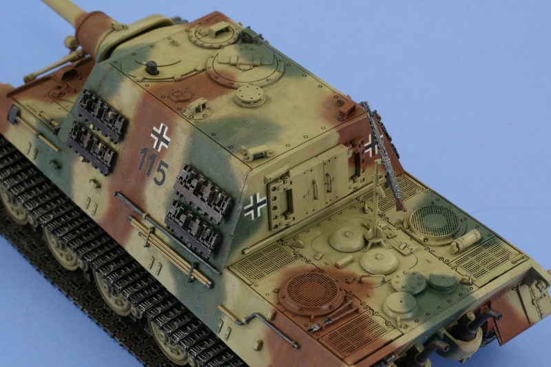
Work continued with the application of a coat of Future which was allowed to air dry for an hour or so before the decals went on. I used the kit-supplied markings for vehicle 115 of the s.PzJgAbt 653 (according to the kit finishing guide). Each of the decals was given multiple doses of Walther's Solvaset in order to get them to snug down tight to the surface and once everything had dried, a second coat of Future was applied and this was allowed to dry overnight last night before the weathering process began.


The weathering process began with the application of a "dot" filter using flat enamel Beret Green, Yellow, White, and Red applied with a spotter brush. The dots were then blended together using a round 0 sable brush dampened with thinner.


This was followed by a pin-wash of Burnt Umber applied with a 10/0 pointed brush working one section at a time. Due to the large surface area and lots of panel lines, bolt heads, etc. this took quite a bit of time and required several breaks in between to avoid the urge to rush through it. Any excess or "blooming" was removed with a brush dampened with thinner where needed.

Work continued with the application of a coat of Future which was allowed to air dry for an hour or so before the decals went on. I used the kit-supplied markings for vehicle 115 of the s.PzJgAbt 653 (according to the kit finishing guide). Each of the decals was given multiple doses of Walther's Solvaset in order to get them to snug down tight to the surface and once everything had dried, a second coat of Future was applied and this was allowed to dry overnight last night before the weathering process began.
The weathering process began with the application of a "dot" filter using flat enamel Beret Green, Yellow, White, and Red applied with a spotter brush. The dots were then blended together using a round 0 sable brush dampened with thinner.
This was followed by a pin-wash of Burnt Umber applied with a 10/0 pointed brush working one section at a time. Due to the large surface area and lots of panel lines, bolt heads, etc. this took quite a bit of time and required several breaks in between to avoid the urge to rush through it. Any excess or "blooming" was removed with a brush dampened with thinner where needed.
-
Bill Plunk
- Posts: 1245
- Joined: Wed Sep 28, 2022 10:18 pm
WIP 06-14-2008
This one got shelved for a couple of weeks due to other things getting in the way as they so often do when it comes to the summer and model building! I was able to get back to it today though and carry on with the weathering process.
First up were the tracks and suspension. I mixed up a batch of equal parts Europe Dust, Dry Mud, and African Earth Mig Pigments in water and applied it wet and allowed it to air dry.

Using a combination of stiff bristled brushes and moistened q-tips, I went to work to remove the excess and get the look I wanted. There's a lot of surface area and the pigment dust is very fine, so I wore a sanding dust mask the entire time and took frequent breaks. After about an hour or so of careful work, the result emerged.

The same thing was repeated for the opposite side, so most of the day ended up being devoted to the tracks. Next up was the weathering for the upper hull and surfaces. I decided on giving it a light dust coat using the same mixture as for the tracks but much more heavily diluted with water to avoid a thick coat. This leaves behind a very very light pigment treatment and I followed behind that with a water dampened sable brush to create rain-streaking and adjust the coverage where needed.

There's some adjustments that I still need to do on the engine deck to get it where I want it, but it's 99% done at this point.
First up were the tracks and suspension. I mixed up a batch of equal parts Europe Dust, Dry Mud, and African Earth Mig Pigments in water and applied it wet and allowed it to air dry.
Using a combination of stiff bristled brushes and moistened q-tips, I went to work to remove the excess and get the look I wanted. There's a lot of surface area and the pigment dust is very fine, so I wore a sanding dust mask the entire time and took frequent breaks. After about an hour or so of careful work, the result emerged.
The same thing was repeated for the opposite side, so most of the day ended up being devoted to the tracks. Next up was the weathering for the upper hull and surfaces. I decided on giving it a light dust coat using the same mixture as for the tracks but much more heavily diluted with water to avoid a thick coat. This leaves behind a very very light pigment treatment and I followed behind that with a water dampened sable brush to create rain-streaking and adjust the coverage where needed.
There's some adjustments that I still need to do on the engine deck to get it where I want it, but it's 99% done at this point.
-
Bill Plunk
- Posts: 1245
- Joined: Wed Sep 28, 2022 10:18 pm
Completion 06-15-2008
After tinkering around the edges a bit today, it was off to the photo booth for the finished shots.


-
Bill Plunk
- Posts: 1245
- Joined: Wed Sep 28, 2022 10:18 pm
Publication January 2009
This build has also been featured in Kagero Publishing's Super Model Nr. 20 on pp. 62-65 published January 2009.

