
Dragon Sdkfz 234/2 Puma (2009)
-
Bill Plunk
- Posts: 1245
- Joined: Wed Sep 28, 2022 10:18 pm
Dragon Sdkfz 234/2 Puma (2009)
Build log for Dragon kit# 6256 Sdkfz 234/2 Puma with Griffon replacement barrel and Echelon peel-and-stick mirrors.
-
Bill Plunk
- Posts: 1245
- Joined: Wed Sep 28, 2022 10:18 pm
WIP 08-14-2009
I had a free evening yesterday due to the fact that my wife was out at a parent-teacher open house for her school so I decided to do something I rarely ever do...and that's start another build before the current one is completed. Rest assured though that the RSO w/ Pak 40 will resume getting its due attention tomorrow for painting!
I have all 4 of DML's Sdkfz 234 kits in the stash and the /2 is the only one that I don't have a whole lot of AM stuff to go with it so I decided to make this one a "guinea pig" of sorts and just build it OOB with the only addition being the Griffon barrel that I had picked up a while back on sale to round out an order to qualify for free shipping. Work began in Step 1 by preparing the chassis tub and installing the longitudinal braces and some detail parts.

Step 2 installs the steering gear and mount hubs for the 8 wheels. The kit diagram here is needlessly confusing and busy IMHO since it insists on numbering each individual part with an arrow to go with it even though all of the parts install exactly the same with the exception of the wheel hubs. These hubs, parts D18 and D19, are directional in terms of front and rear and are the ones you have to be the most careful about. In order to insure I didn't miss any parts in this step, I crossed out each part number as I worked through the installation until all 8 stations had been assembled and in place. The steering arms aren't positionable without modification and I decided to just leave mine all in the straight alignment for simplicity's sake. It is worth noting that you need to think through the order of the parts placement as the D18/19 hubs are designed to be trapped between the upper and lower frames and the pin sizes are different to help insure they all get aligned in the right direction.

Step 3 continues work with the suspension by adding the leaf spring bundles and their mount points. The springs have fine mold seams that need to be carefully removed top and bottom but otherwise are beautifully molded. The springs did need a little encouragement to sit properly on their attachment ends and I used some smooth-jawed copper soldering clamps and liquid glue to firmly seat them in position.

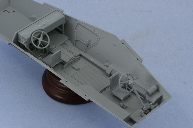
Step 4 is a sub-assembly step that prepares several items for installation into the lower hull tub in the interior. The front and rear driver's seats are assembled along with the foot pedal arrangements and the steering wheels. The pedals are very nicely detailed, with molded on "K" and "B" details for "gas" and "brakes"! The rear bulkhead and fuel tank is also assembled and the bulkhead has 4 mounting holes that have to be opened up with a pin vise to allow the tank to mount properly.

Steps 5 and 6 deal with the installation of various parts into the interior including those assembled in Step 4. I made the mistake of installing the rear bulkhead/fuel tank combo first when I should have done it last. This was a mistake in the sense that it made the installation of all the other detail parts much harder due to the confined space...something I'll have to remember when I build the others in the future. I had decided not to paint the interior since this one is a closed top but there are some raised ejector marks that would be visible on the finished interior if it were exposed, so those too would have to be dealt with on future builds.
I built the Italeri kit some time back and it doesn't even come close to comparing to this DML kit in terms of detail and molding quality. This one will sit for a little while as work continues on the RSO but I'll be back to it soon, no doubt of that!
I have all 4 of DML's Sdkfz 234 kits in the stash and the /2 is the only one that I don't have a whole lot of AM stuff to go with it so I decided to make this one a "guinea pig" of sorts and just build it OOB with the only addition being the Griffon barrel that I had picked up a while back on sale to round out an order to qualify for free shipping. Work began in Step 1 by preparing the chassis tub and installing the longitudinal braces and some detail parts.
Step 2 installs the steering gear and mount hubs for the 8 wheels. The kit diagram here is needlessly confusing and busy IMHO since it insists on numbering each individual part with an arrow to go with it even though all of the parts install exactly the same with the exception of the wheel hubs. These hubs, parts D18 and D19, are directional in terms of front and rear and are the ones you have to be the most careful about. In order to insure I didn't miss any parts in this step, I crossed out each part number as I worked through the installation until all 8 stations had been assembled and in place. The steering arms aren't positionable without modification and I decided to just leave mine all in the straight alignment for simplicity's sake. It is worth noting that you need to think through the order of the parts placement as the D18/19 hubs are designed to be trapped between the upper and lower frames and the pin sizes are different to help insure they all get aligned in the right direction.
Step 3 continues work with the suspension by adding the leaf spring bundles and their mount points. The springs have fine mold seams that need to be carefully removed top and bottom but otherwise are beautifully molded. The springs did need a little encouragement to sit properly on their attachment ends and I used some smooth-jawed copper soldering clamps and liquid glue to firmly seat them in position.
Step 4 is a sub-assembly step that prepares several items for installation into the lower hull tub in the interior. The front and rear driver's seats are assembled along with the foot pedal arrangements and the steering wheels. The pedals are very nicely detailed, with molded on "K" and "B" details for "gas" and "brakes"! The rear bulkhead and fuel tank is also assembled and the bulkhead has 4 mounting holes that have to be opened up with a pin vise to allow the tank to mount properly.
Steps 5 and 6 deal with the installation of various parts into the interior including those assembled in Step 4. I made the mistake of installing the rear bulkhead/fuel tank combo first when I should have done it last. This was a mistake in the sense that it made the installation of all the other detail parts much harder due to the confined space...something I'll have to remember when I build the others in the future. I had decided not to paint the interior since this one is a closed top but there are some raised ejector marks that would be visible on the finished interior if it were exposed, so those too would have to be dealt with on future builds.
I built the Italeri kit some time back and it doesn't even come close to comparing to this DML kit in terms of detail and molding quality. This one will sit for a little while as work continues on the RSO but I'll be back to it soon, no doubt of that!
-
Bill Plunk
- Posts: 1245
- Joined: Wed Sep 28, 2022 10:18 pm
WIP 08-20-2009
Managed to get some more work done on this one here and there. Continuing on in the instructions with Step 8, the lower hull was joined to the chassis and the remaining tie rods and steering gear installed. Based on my experience with the instruction order, I have to say that I think it's better to add the tub to the chassis before adding the interior details as I needed to use a couple of rubber bands to get an even join front to back and the presence of the interior details made this harder than it would've been otherwise. I also completed the installation of the spring parts from Step 9 at this point, another tricky assembly due to the fact that the slots molded in the hull side for the D2 parts weren't a good fit. This meant that the parts had to be trimmed and/or sanded down slightly to fit properly.

Step 10 added the little wing-like protections for the front and rear suspensions and also calls for the installation of the inner wheel hubs. I'm not exactly sure why that's called for at this point since the actual wheel installation doesn't take place until the very end in Step 25. I cleaned up the hubs and dry-fit them just to see how the vehicle would sit. So far all the points make contact so that's a good thing. The hubs were set off to the side and will be added to the wheels later on.

The instructions contain another oddity in Step 11 in that this step includes details and options for the armored visors depending on whether they are in the open or closed position but doesn't actually assemble anything. That's because the parts you need to complete the visors, the external armored covers, aren't called out as parts numbers until Steps 12 and 13! Both of those steps add details to the interior of the upper hull half and I installed the front set of visors for the driver in the workable mode so they could be posed open later on. The rear set I installed in the closed position. The other interior details were also added just to see how it would all look as a practice run for future 234-based builds but none of it will be visible on the finished build unless the turret is removed. I also opted for the open vents for the engine deck and those were installed as well to round things out.


Step 15 is a very important step as it joins the upper and lower hull together and also adds the side bins and fenders. Test fit of the hull halves was generally good with just some slight gaps at the rear due to the angle of the rear bulkhead in the interior. I trimmed this down a bit with a shark knife and that resolved most of the problem with some strategic rubber bands taking care of the rest. The rear hull plate was also added to insure proper alignment with the top and bottom.

Once the glue had set, the rubber bands came off and the side fenders were added. I wasn't paying close enough attention and didn't realize that I had neglected to add the inner portions that represent the stowage boxes. The instruction diagram shows these as already installed to the hull side with number call outs and I completely missed that before adding the side fenders. Of course, the glue had already started to set so I had to carefully remove the fenders from both sides, install the boxes, then re-attach the fenders. This resulted in some slight glue damage to the hull sides that required some careful putty work and sanding to correct and restore everything back to the way it should've been if I'd been paying a little more attention. Something to remember for next time for sure!


Next up will be tackling all the various gear that goes on the fenders, some of which will be installed right away and others left off until after painting.
Step 10 added the little wing-like protections for the front and rear suspensions and also calls for the installation of the inner wheel hubs. I'm not exactly sure why that's called for at this point since the actual wheel installation doesn't take place until the very end in Step 25. I cleaned up the hubs and dry-fit them just to see how the vehicle would sit. So far all the points make contact so that's a good thing. The hubs were set off to the side and will be added to the wheels later on.
The instructions contain another oddity in Step 11 in that this step includes details and options for the armored visors depending on whether they are in the open or closed position but doesn't actually assemble anything. That's because the parts you need to complete the visors, the external armored covers, aren't called out as parts numbers until Steps 12 and 13! Both of those steps add details to the interior of the upper hull half and I installed the front set of visors for the driver in the workable mode so they could be posed open later on. The rear set I installed in the closed position. The other interior details were also added just to see how it would all look as a practice run for future 234-based builds but none of it will be visible on the finished build unless the turret is removed. I also opted for the open vents for the engine deck and those were installed as well to round things out.
Step 15 is a very important step as it joins the upper and lower hull together and also adds the side bins and fenders. Test fit of the hull halves was generally good with just some slight gaps at the rear due to the angle of the rear bulkhead in the interior. I trimmed this down a bit with a shark knife and that resolved most of the problem with some strategic rubber bands taking care of the rest. The rear hull plate was also added to insure proper alignment with the top and bottom.
Once the glue had set, the rubber bands came off and the side fenders were added. I wasn't paying close enough attention and didn't realize that I had neglected to add the inner portions that represent the stowage boxes. The instruction diagram shows these as already installed to the hull side with number call outs and I completely missed that before adding the side fenders. Of course, the glue had already started to set so I had to carefully remove the fenders from both sides, install the boxes, then re-attach the fenders. This resulted in some slight glue damage to the hull sides that required some careful putty work and sanding to correct and restore everything back to the way it should've been if I'd been paying a little more attention. Something to remember for next time for sure!
Next up will be tackling all the various gear that goes on the fenders, some of which will be installed right away and others left off until after painting.
-
Bill Plunk
- Posts: 1245
- Joined: Wed Sep 28, 2022 10:18 pm
WIP 08-28-2009
Made some more progress here and there on the various details with this build now that the hull and fenders were all in one piece. The first area in Step 16 deals with the front and installs the bumper, Bosch headlights, and width indicators. I opted for the supplied brass width indicator posts and, while the instructions don't mention it, there's a bending guide provided on the back of sprue TF. The guide itself isn't stiff enough to do the actual bending but using a pair of pliers and checking with the guide insured I got the desired angle. You do have to be careful to install the right guide for the side with the driver's mirror as it has the little mounting bracket as an added detail. The kit tries to help with this by packaging them separately on the card insert for the multi-media but once you get them out of the package it's easy to confuse them if not paying attention. The posts were glued in position with small amounts of CA gel and mated perfectly with the provided mount holes.

Step 17 is a simple step that deals with the rear hull and provides the option of fitting the spare tire holder or not. I opted for the holder but left the actual wheel off for now since that will be painted and installed separately.

Step 18 continues the work on the rear with the assembly and installation of the mufflers and rear fender extensions. There is a small error in the instructions in that the exhaust pipes that connect the hull side to the mufflers are labeled backwards, part E42 actually belongs on the right side and E47 on the left, something easily discovered once you try to fit them as directed since the angles don't line up properly. The right side muffler has the option to have the exhaust pipe pointing either inward or outward and I opted for the outward configuration. Some slight putty work was needed to fill small gaps for the exhaust pipe on both sides. The rear Notek light was added as well and the kit provides two options...one with the flap molded on in the down position and one with a PE flap and the option to pose in either the up or down position. I went with the molded on part since I had no particular reason to show the flap in the up position...it's a nice detail consideration though and will go into the spares bin for possible use on future projects.

Step 19 begins the work on the fender details with the left side going first. It's a busy step with a lot of parts and sub-assemblies for the jack and the jerry cans, so you have to be careful not to miss anything along the way. A small molded on projection has to be removed for this variant, something that was easily done with sprue cutters and then carefully sanded down. I added the optional MG ammunition box and also went with the rear 2 jerry can racks instead of the extra stowage box option. I used the kit supplied PE lifting hooks instead of the styrene parts as they were more in-scale and smaller than the styrene parts. That meant that the molded on locator points had to be removed first and sanded down before gluing the hooks in place with small amounts of Gator Grip glue to allow some work time for their proper alignment and positioning. In order to facilitate painting and detailing, I left the jerry cans and the upper portions of their holders off for now along with most of the pioneer tools.

Step 20 continues the effort with the right side fender. I opted here as well for the optional 5.0cm ammunition box but only mounted the PE holders so that the box could be detailed separately before installation. There aren't any locator marks, just a small diagram indicating that the rearmost holder be 22.5mm in from the bend in the front fender...so I carefully bent the holder to shape and then installed it first, placed the box in that holder and then installed the second bracket so that the two would align properly but still allow the box to slide in and out for later installation.

All of the fender gear was removed from the sprues, cleaned up, and assembled where needed even though it wasn't going to be installed just yet. The jack came integrated with the top brackets for the holders and all of the tools have molded on clamps/holders as well. I will add the missing clamp handles with Griffon parts later on just before installation. The six jerry cans assembled beautifully with no issues and are a revised design from previous DML kits in regards to the spouts and handles. They don't have any stamping as to type so can all be done as fuel cans. The 5.0cm ammo box did have a seam on the top that required some careful putty and sanding work to correct. I also slightly modified the shovels by thinning down the rear shovel head edges with a #11 blade to give them a more in-scale thickness.

Next up will be the turret and gun!
Step 17 is a simple step that deals with the rear hull and provides the option of fitting the spare tire holder or not. I opted for the holder but left the actual wheel off for now since that will be painted and installed separately.
Step 18 continues the work on the rear with the assembly and installation of the mufflers and rear fender extensions. There is a small error in the instructions in that the exhaust pipes that connect the hull side to the mufflers are labeled backwards, part E42 actually belongs on the right side and E47 on the left, something easily discovered once you try to fit them as directed since the angles don't line up properly. The right side muffler has the option to have the exhaust pipe pointing either inward or outward and I opted for the outward configuration. Some slight putty work was needed to fill small gaps for the exhaust pipe on both sides. The rear Notek light was added as well and the kit provides two options...one with the flap molded on in the down position and one with a PE flap and the option to pose in either the up or down position. I went with the molded on part since I had no particular reason to show the flap in the up position...it's a nice detail consideration though and will go into the spares bin for possible use on future projects.
Step 19 begins the work on the fender details with the left side going first. It's a busy step with a lot of parts and sub-assemblies for the jack and the jerry cans, so you have to be careful not to miss anything along the way. A small molded on projection has to be removed for this variant, something that was easily done with sprue cutters and then carefully sanded down. I added the optional MG ammunition box and also went with the rear 2 jerry can racks instead of the extra stowage box option. I used the kit supplied PE lifting hooks instead of the styrene parts as they were more in-scale and smaller than the styrene parts. That meant that the molded on locator points had to be removed first and sanded down before gluing the hooks in place with small amounts of Gator Grip glue to allow some work time for their proper alignment and positioning. In order to facilitate painting and detailing, I left the jerry cans and the upper portions of their holders off for now along with most of the pioneer tools.
Step 20 continues the effort with the right side fender. I opted here as well for the optional 5.0cm ammunition box but only mounted the PE holders so that the box could be detailed separately before installation. There aren't any locator marks, just a small diagram indicating that the rearmost holder be 22.5mm in from the bend in the front fender...so I carefully bent the holder to shape and then installed it first, placed the box in that holder and then installed the second bracket so that the two would align properly but still allow the box to slide in and out for later installation.
All of the fender gear was removed from the sprues, cleaned up, and assembled where needed even though it wasn't going to be installed just yet. The jack came integrated with the top brackets for the holders and all of the tools have molded on clamps/holders as well. I will add the missing clamp handles with Griffon parts later on just before installation. The six jerry cans assembled beautifully with no issues and are a revised design from previous DML kits in regards to the spouts and handles. They don't have any stamping as to type so can all be done as fuel cans. The 5.0cm ammo box did have a seam on the top that required some careful putty and sanding work to correct. I also slightly modified the shovels by thinning down the rear shovel head edges with a #11 blade to give them a more in-scale thickness.
Next up will be the turret and gun!
-
Bill Plunk
- Posts: 1245
- Joined: Wed Sep 28, 2022 10:18 pm
WIP 08-30-2009
Work continued this weekend picking up from last time and continuing on with the remaining construction steps. Step 21 dealt with the assembly of the main gun breech and offers up a decent level of detail. Care has to be taken when attaching C9 and C27 to insure that the gun will remain able to elevate should you so desire. The instructions are a little vague on exactly where you can glue so test fits are a must before you commit.

Step 22 assembles the main gun and I swapped out the kit supplied styrene barrel for the Griffon replacement. The Griffon barrel is designed for this kit specifically and was a perfect fit into the mantlet with no modifications required. The only modification I made at this point was to drill out the solid muzzle on the coaxial MG before its installation. There isn't any interior detail for this MG, something that will be readily apparent if the turret hatches are left open. I'm closing all mine up so this isn't a worry to me in the long run.

Step 23 and 24 assemble the turret and install the main gun and there are several options presented in these steps. I opted to install the hatches in the closed position and will also install the large periscope in the raised position after painting to make it easier to detail it first. The same is also true for the normal periscopes for both the gunner and the loader. There is a small error in these steps to watch out for, the parts numbers for the base mounts for the smoke launchers parts C23 and C20 have to be installed in the reverse from what is called for in the instructions. I modified the turret antenna mount by clipping off the styrene rod portion and retaining just the base. The base was drilled out with a #72 finger drill in order to accept a brass antenna later on and then glued in place on the turret. The main gun was then installed and i was pleased to see that there's sufficient friction in the gun mount itself to support the gun without gluing it into a fixed position.

Step 25 is the final step in the instructions and calls for the assembly of the wheels and their installation. Since DML designed the hubs separate from the tires, I decided to remove all the parts from the sprues and clean them up but only assembled the hubs and left the tire halves separate for painting first. I opted for the outer hubs with the 5 lightening openings instead of the 2 and assembled all 8 hubs plus the spare tire for 9 in total.

The step also calls for the installation of the base for the stern antenna and this was added without difficulty, again modifying the base by drilling to accept a brass antenna to go with the kit supplied PE-star top later on. The turret was also test fitted to make sure everything lined up properly. I also decided to go ahead and install the jerry cans in their holders. I had to trim parts B11 on their undersides to get them to sit properly and mate up with the lower halves of the holders due to the fact that they have small ejector marks present. This was easily done with a #11 blade and then the holders were glued into place along with the cans. Originally I'd toyed with the idea of painting some of them panzer gray but decided it was too gimmicky and kept all the cans in dunkelgelb in the end.

That meant that it was now time for paint, so the turret was mounted separately on my all-purpose turret holder of choice, a cut-down toilet paper cardboard tube fitted with strips of blue painter's tape. A primer coat of enamel Italian Dark Brown was applied by airbrush to get the ball rolling.

Then the base coat of 50/50 enamel Light Gray/Panzer Dunkelgelb was applied.

Then came the camo patterns. I used a combination of the box art and the kit supplied guide for the 20 Pz. Div. Bohemia 1945 vehicle and free handed the pattern by air brush. I applied the rotbraun sections first using a 50/50 mix of Leather/Military Brown and then the olivgrun sections second using straight enamel Khaki. Once the pattern was on, I sprayed a mist coat of the base coat from a distance of about 12" to blend everything back together and give it a slightly faded look.


And the last item of business for the day...the wheels. I had attached the hubs and tire halves to long strips of painter's tape for easier handling. Both received a primer coat at the same time as the vehicle and then the hubs were base coated with the same lightened dunkelgelb mix. The tire halves were painted with enamel Gunmetal and then the tires and hubs were assembled together. The fit was a little tight so I used rubber bands and regular glue to insure an even join all around. Once set, I touched up the mid-tire channel gap with Gunmetal again by airbrush and everything was good to go.

Next steps will be to start in on the vehicle details and get them mounted.
Step 22 assembles the main gun and I swapped out the kit supplied styrene barrel for the Griffon replacement. The Griffon barrel is designed for this kit specifically and was a perfect fit into the mantlet with no modifications required. The only modification I made at this point was to drill out the solid muzzle on the coaxial MG before its installation. There isn't any interior detail for this MG, something that will be readily apparent if the turret hatches are left open. I'm closing all mine up so this isn't a worry to me in the long run.
Step 23 and 24 assemble the turret and install the main gun and there are several options presented in these steps. I opted to install the hatches in the closed position and will also install the large periscope in the raised position after painting to make it easier to detail it first. The same is also true for the normal periscopes for both the gunner and the loader. There is a small error in these steps to watch out for, the parts numbers for the base mounts for the smoke launchers parts C23 and C20 have to be installed in the reverse from what is called for in the instructions. I modified the turret antenna mount by clipping off the styrene rod portion and retaining just the base. The base was drilled out with a #72 finger drill in order to accept a brass antenna later on and then glued in place on the turret. The main gun was then installed and i was pleased to see that there's sufficient friction in the gun mount itself to support the gun without gluing it into a fixed position.
Step 25 is the final step in the instructions and calls for the assembly of the wheels and their installation. Since DML designed the hubs separate from the tires, I decided to remove all the parts from the sprues and clean them up but only assembled the hubs and left the tire halves separate for painting first. I opted for the outer hubs with the 5 lightening openings instead of the 2 and assembled all 8 hubs plus the spare tire for 9 in total.
The step also calls for the installation of the base for the stern antenna and this was added without difficulty, again modifying the base by drilling to accept a brass antenna to go with the kit supplied PE-star top later on. The turret was also test fitted to make sure everything lined up properly. I also decided to go ahead and install the jerry cans in their holders. I had to trim parts B11 on their undersides to get them to sit properly and mate up with the lower halves of the holders due to the fact that they have small ejector marks present. This was easily done with a #11 blade and then the holders were glued into place along with the cans. Originally I'd toyed with the idea of painting some of them panzer gray but decided it was too gimmicky and kept all the cans in dunkelgelb in the end.
That meant that it was now time for paint, so the turret was mounted separately on my all-purpose turret holder of choice, a cut-down toilet paper cardboard tube fitted with strips of blue painter's tape. A primer coat of enamel Italian Dark Brown was applied by airbrush to get the ball rolling.
Then the base coat of 50/50 enamel Light Gray/Panzer Dunkelgelb was applied.
Then came the camo patterns. I used a combination of the box art and the kit supplied guide for the 20 Pz. Div. Bohemia 1945 vehicle and free handed the pattern by air brush. I applied the rotbraun sections first using a 50/50 mix of Leather/Military Brown and then the olivgrun sections second using straight enamel Khaki. Once the pattern was on, I sprayed a mist coat of the base coat from a distance of about 12" to blend everything back together and give it a slightly faded look.
And the last item of business for the day...the wheels. I had attached the hubs and tire halves to long strips of painter's tape for easier handling. Both received a primer coat at the same time as the vehicle and then the hubs were base coated with the same lightened dunkelgelb mix. The tire halves were painted with enamel Gunmetal and then the tires and hubs were assembled together. The fit was a little tight so I used rubber bands and regular glue to insure an even join all around. Once set, I touched up the mid-tire channel gap with Gunmetal again by airbrush and everything was good to go.
Next steps will be to start in on the vehicle details and get them mounted.
-
Bill Plunk
- Posts: 1245
- Joined: Wed Sep 28, 2022 10:18 pm
WIP 09-06-2009
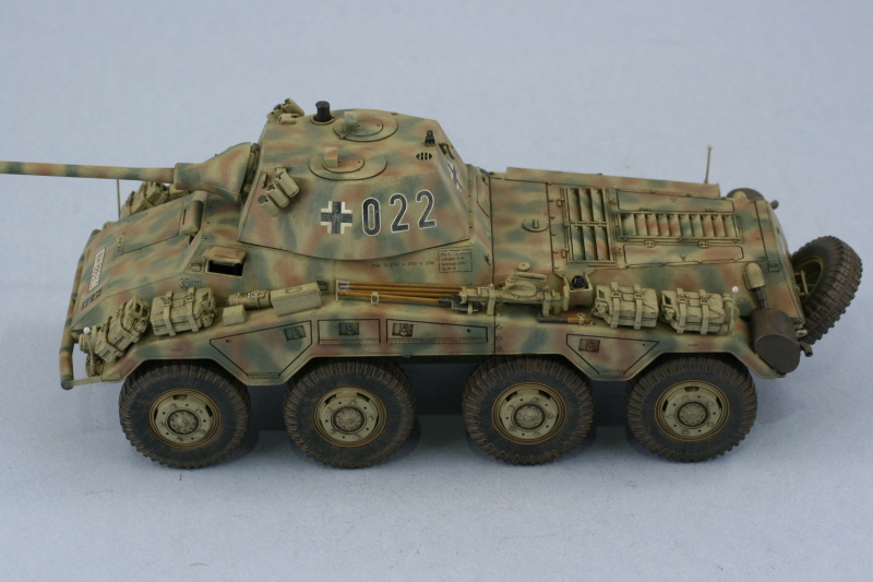
Moving right along with this project, the next order of business was to add all the fender details. All of the pioneer tools were detailed off the vehicle with their metal portions painted with Metalizer Non-buffing Gunmetal and dry brushed with Steel. Their wood portions were painted a light tan "wood" color I have mixed up followed by a light wash of thinned enamel Leather. Once the wash had dried, the wood portions were lightly treated with artist pastel Burnt Umber to complete their look. I added PE clamp handles where appropriate using handles from a generic Griffon PE clamp set. The wire cutters had their Bakelite handles painted with Italian Dark Brown and regular enamel Gunmetal used for the rubber end caps. I also installed the smoke grenades in the launchers, leaving a couple empty for a little variety. The muffler/exhausts were also detailed using the same metalizer Gunmetal base coat followed by successive washes of thinned enamel Rust until I had the desired look. I also installed the turret periscopes and posed the driver's visors in the open position to give it a "crewed" feel. Last but not least, the spare tire was installed to the rear hull as well.


The last remaining major construction detail was the installation of the 8 wheels.

The entire vehicle was then sealed with a coat of Future applied by air brush. After the coat had dried, the decals were added using Solvaset to insure they snugged down tight to the surface. Then a 2nd coat of Future was applied to seal the decals and protect them from the weathering process.

The first step in the weathering was the overall application of a wash of Raw Umber.

This was followed by the application of dot filters using Flat White, Raw Sienna, Panzer Olivgrun, and the 50-50 Light Gray/Dunkelgelb base coat mix. I worked in small sections at a time and blended the dots together with a square tipped blender brush lightly dampened with thinner.


Since the road wheels are so prominent a feature, I decided to do something a little different with them. Instead of weathering them with just pigments, I decided to use a thinned wash of Raw Sienna to prep them for the pigment weathering.

Then a pin wash of Burnt Umber was applied to all the panel lines and raised detail. Excess wash was removed using a clean brush and thinner where needed.
All that's left is to apply pigments to the lower hull and wheels and then install the radio antennas. This one's almost to the finish line.
The last remaining major construction detail was the installation of the 8 wheels.
The entire vehicle was then sealed with a coat of Future applied by air brush. After the coat had dried, the decals were added using Solvaset to insure they snugged down tight to the surface. Then a 2nd coat of Future was applied to seal the decals and protect them from the weathering process.
The first step in the weathering was the overall application of a wash of Raw Umber.
This was followed by the application of dot filters using Flat White, Raw Sienna, Panzer Olivgrun, and the 50-50 Light Gray/Dunkelgelb base coat mix. I worked in small sections at a time and blended the dots together with a square tipped blender brush lightly dampened with thinner.
Since the road wheels are so prominent a feature, I decided to do something a little different with them. Instead of weathering them with just pigments, I decided to use a thinned wash of Raw Sienna to prep them for the pigment weathering.
Then a pin wash of Burnt Umber was applied to all the panel lines and raised detail. Excess wash was removed using a clean brush and thinner where needed.
All that's left is to apply pigments to the lower hull and wheels and then install the radio antennas. This one's almost to the finish line.
-
Bill Plunk
- Posts: 1245
- Joined: Wed Sep 28, 2022 10:18 pm
Completion 09-07-2009
Taking advantage of the Labor Day holiday, work continued today on the finishing touches. I made a couple minor adjustments here and there to the washes and weathering from yesterday and then sealed the entire vehicle with a coat of Testors Lusterless Flat lacquer in the spray can.

Once that had dried, I went to work on the underside of the hull and suspension. I applied a thin wet mix of Mig Dark Mud pigment and water with a drop of soap added and let that air dry which took about 15 minutes due to the dilute nature of the mix. Using several q-tips, I removed the excess and adjusted it to my liking on the different surfaces. Most of this isn't visible unless you turn the vehicle over but since the display case it will go in has clear shelves, it will be visible there so I decided to go ahead and weather it.

With that out of the way, it was time to install the remaining details. First up were the brass antennas for the turret and hull side mounts. The turret antenna is from Armorscale while the hull side is from RB Models in combination with the DML provided star mast top. The antennas were installed with CA gel and then painted with non-buffing Metalizer Gunmetal to complete their look.


Then it was just one last check in the mirror, courtesy of the Echelon peel-and-stick-mirrors, before heading off to the photo booth for the final shots.


Once that had dried, I went to work on the underside of the hull and suspension. I applied a thin wet mix of Mig Dark Mud pigment and water with a drop of soap added and let that air dry which took about 15 minutes due to the dilute nature of the mix. Using several q-tips, I removed the excess and adjusted it to my liking on the different surfaces. Most of this isn't visible unless you turn the vehicle over but since the display case it will go in has clear shelves, it will be visible there so I decided to go ahead and weather it.
With that out of the way, it was time to install the remaining details. First up were the brass antennas for the turret and hull side mounts. The turret antenna is from Armorscale while the hull side is from RB Models in combination with the DML provided star mast top. The antennas were installed with CA gel and then painted with non-buffing Metalizer Gunmetal to complete their look.
Then it was just one last check in the mirror, courtesy of the Echelon peel-and-stick-mirrors, before heading off to the photo booth for the final shots.
-
Bill Plunk
- Posts: 1245
- Joined: Wed Sep 28, 2022 10:18 pm
Publication February 2010
This build has been published on pp. 66-68 in Scale Military Modeler International February 2010 Issue

