
Tamiya Sdkfz 124 Wespe leFH18/2 auf GW II (2010)
-
Bill Plunk
- Posts: 1245
- Joined: Wed Sep 28, 2022 10:18 pm
Tamiya Sdkfz 124 Wespe leFH18/2 auf GW II (2010)
Build log for Tamiya kit #35200 leFH18/2 Auf GW II Sdkfz 124 Wespe with Model Kasten workable tracks, Eduard PE details, Tiger Model Designs (TMD) resin leFH 18/SiG 33 sight, TMD leFH18 10.5cm resin ammunition, JB Models brass 10.5cm cartridge cases, Armorscale turned aluminum and brass 10.5cm barrel, and Echelon Fine Details decals.
-
Bill Plunk
- Posts: 1245
- Joined: Wed Sep 28, 2022 10:18 pm
WIP 07-03-2010
Since the last project completed, it's been an interesting few days. I had a PC crash that took a week for me to get repaired and files restored more or less and in the meantime was able to start work on a kit I'd been wanting to tackle for a while, the Tamiya Wespe.
I started off following the instruction order with Step 1 which deals with the road wheels, sprockets, and idlers. The road wheels only required minimal cleanup and sprockets were easily assembled as well although some care was needed to remove the sprue attachment points and avoid damaging the drive teeth in the process. The idlers received the Eduard PE outer rims in place of the kit parts to provide a more in-scale appearance. I also went ahead and cleaned up the return rollers even though they aren't called for until Step 3.

Step 2 deals with the lower hull and adds all the suspension swing arms and support springs. The suspension arms required some seam clean up and I also installed the tow hitch and Notek light to the rear hull along with the exhaust pipe on the right hand side. The MK track set includes movable adapters for the idler mount to allow for proper track tensioning later on but to install these the hull requires some hefty modification. The molded on idler mounts were removed and the necessary openings drilled out in the hull to take the MK adapters. The holes were then carefully cleaned up to preserve the detail with a #11 blade and then shaped smooth with a round needle file to complete the job. The Eduard set included the missing detail of the track pin nudge plates, so these were assembled and glued in place with Gator Grip glue to allow for some work time in their placement.


Step 3 calls for the installation of all the road wheels, sprockets, idlers, and return rollers but these were left off for the time being to facilitate painting later on. The step also calls for the assembly of the rear exhaust muffler and its install to the rear hull. I added the Eduard PE heat shield as well as the Eduard bolt detail strips for the join plate on the rear hull to add some detail missing from the Tamiya parts. The heat shield was annealed over a gas flame and then shaped to the necessary curve and glued in place with CA gel at the top bolt tabs.

Step 4 began work on the interior and adds the rear fighting compartment elements to the lower hull. The firewall for the engine compartment was added along with the raised crew floor. I also installed the ammunition boxes as directed in this step and will display both of them open and populated with the TMD ammo. Missing on the inside were the second level round holders/braces, so I added these using parts from a second Eduard detail set that was for the Wespe cartridge cases only. The Eduard parts had to be cut down and trimmed to fit the ammunition boxes but look the part which is all that matters once the rounds are installed. The rear gun travel lock was also added to round things out for this step.

Step 5 deals with the business end of the vehicle, the leFH18. The Armorscale barrel includes a resin breech so the only parts used from the Tamiya kit for the gun itself is B10, the recoil sled. This required some slight modification to remove the tab on the end and was joined to the barrel with CA gel. The resin breech had lost the vertical part of the block lever, so I removed that and used the Tamiya kit part instead to repair the damage.
The recoil mount and overhead cylinder were installed as per the instructions and the slight mold seams sanded smooth on the round parts with a sanding twig to avoid creating a flat spot in the process. Small amounts of putty were needed to fill gaps around the rear of the cylinder where the two part halves joined but otherwise the fit was good.

Steps 6 and 7 install the gun onto the recoil mount and then adds the gun mount halves themselves to create a single assembly. I replaced the kit gun sight with the TMD resin sight and this required some modification to the kit part B9 and checking of references to be sure I had the sight mounted in the right position. The gun is able to elevate completely and all of the other details like the elevation/traverse wheels/gears and the equilibrator were also added in these steps. The recoil piston rod that connects the breech to the recoil cylinder was not included in either the Tamiya parts or the Armorscale parts, so I created this using a short length of styrene rod and drilled small holes in both parts with a #76 finger drill and glued it in place with CA gel to add that little detail.


That led to Step 8 and the gun splinter shield. The shield had some prominent ejector marks visible on the inside so these were carefully sanded down and the cylindrical cases for the gun sight and the gun cleaning swab installed. The depressions in the shield for these cases had some gaps that were filled with Squadron White putty and sanded smooth.

The shield was then installed to the gun to complete the step.

That brought me to Step 9 which began work on the upper hull deck. The step calls for the installation of the engine side intakes as well as the driver's hood hatches. The hatches were all installed in the closed position since I didn't want to show that area without an interior. The gun travel lock was also assembled and installed with the lock itself left movable. The two front lifting eyes were removed with a #11 blade and replaced with the Eduard items using CA gel to insure they didn't get lost in later handling. I also filled in all of the mount holes for the fender tools since they will receive Eduard clamps when the time comes and it was easier to deal with it now before it's joined to the lower hull.

The Eduard set includes quite a bit of detail for the fighting compartment area that the Tamiya kit misses entirely. Using the Eduard set, the tread plate for the side panels was added along with the bolt strips for the side armor of the fighting compartment. I used Lion Roar hex nuts to add the bolts themselves and only added them to areas that would be visible once the gun was installed. I also added the engine starter crank holders and will add the actual crank later on using a modified spare crank from the spares bin since the Tamiya kit didn't include one. Lifting eyes were added as well along with the engine fuel and oil pump levers.

Next up will be the fighting compartment sides since those need to be done individually and painted along with the gun before the gun can be installed and the sides added.
I started off following the instruction order with Step 1 which deals with the road wheels, sprockets, and idlers. The road wheels only required minimal cleanup and sprockets were easily assembled as well although some care was needed to remove the sprue attachment points and avoid damaging the drive teeth in the process. The idlers received the Eduard PE outer rims in place of the kit parts to provide a more in-scale appearance. I also went ahead and cleaned up the return rollers even though they aren't called for until Step 3.
Step 2 deals with the lower hull and adds all the suspension swing arms and support springs. The suspension arms required some seam clean up and I also installed the tow hitch and Notek light to the rear hull along with the exhaust pipe on the right hand side. The MK track set includes movable adapters for the idler mount to allow for proper track tensioning later on but to install these the hull requires some hefty modification. The molded on idler mounts were removed and the necessary openings drilled out in the hull to take the MK adapters. The holes were then carefully cleaned up to preserve the detail with a #11 blade and then shaped smooth with a round needle file to complete the job. The Eduard set included the missing detail of the track pin nudge plates, so these were assembled and glued in place with Gator Grip glue to allow for some work time in their placement.
Step 3 calls for the installation of all the road wheels, sprockets, idlers, and return rollers but these were left off for the time being to facilitate painting later on. The step also calls for the assembly of the rear exhaust muffler and its install to the rear hull. I added the Eduard PE heat shield as well as the Eduard bolt detail strips for the join plate on the rear hull to add some detail missing from the Tamiya parts. The heat shield was annealed over a gas flame and then shaped to the necessary curve and glued in place with CA gel at the top bolt tabs.
Step 4 began work on the interior and adds the rear fighting compartment elements to the lower hull. The firewall for the engine compartment was added along with the raised crew floor. I also installed the ammunition boxes as directed in this step and will display both of them open and populated with the TMD ammo. Missing on the inside were the second level round holders/braces, so I added these using parts from a second Eduard detail set that was for the Wespe cartridge cases only. The Eduard parts had to be cut down and trimmed to fit the ammunition boxes but look the part which is all that matters once the rounds are installed. The rear gun travel lock was also added to round things out for this step.
Step 5 deals with the business end of the vehicle, the leFH18. The Armorscale barrel includes a resin breech so the only parts used from the Tamiya kit for the gun itself is B10, the recoil sled. This required some slight modification to remove the tab on the end and was joined to the barrel with CA gel. The resin breech had lost the vertical part of the block lever, so I removed that and used the Tamiya kit part instead to repair the damage.
The recoil mount and overhead cylinder were installed as per the instructions and the slight mold seams sanded smooth on the round parts with a sanding twig to avoid creating a flat spot in the process. Small amounts of putty were needed to fill gaps around the rear of the cylinder where the two part halves joined but otherwise the fit was good.
Steps 6 and 7 install the gun onto the recoil mount and then adds the gun mount halves themselves to create a single assembly. I replaced the kit gun sight with the TMD resin sight and this required some modification to the kit part B9 and checking of references to be sure I had the sight mounted in the right position. The gun is able to elevate completely and all of the other details like the elevation/traverse wheels/gears and the equilibrator were also added in these steps. The recoil piston rod that connects the breech to the recoil cylinder was not included in either the Tamiya parts or the Armorscale parts, so I created this using a short length of styrene rod and drilled small holes in both parts with a #76 finger drill and glued it in place with CA gel to add that little detail.
That led to Step 8 and the gun splinter shield. The shield had some prominent ejector marks visible on the inside so these were carefully sanded down and the cylindrical cases for the gun sight and the gun cleaning swab installed. The depressions in the shield for these cases had some gaps that were filled with Squadron White putty and sanded smooth.
The shield was then installed to the gun to complete the step.
That brought me to Step 9 which began work on the upper hull deck. The step calls for the installation of the engine side intakes as well as the driver's hood hatches. The hatches were all installed in the closed position since I didn't want to show that area without an interior. The gun travel lock was also assembled and installed with the lock itself left movable. The two front lifting eyes were removed with a #11 blade and replaced with the Eduard items using CA gel to insure they didn't get lost in later handling. I also filled in all of the mount holes for the fender tools since they will receive Eduard clamps when the time comes and it was easier to deal with it now before it's joined to the lower hull.
The Eduard set includes quite a bit of detail for the fighting compartment area that the Tamiya kit misses entirely. Using the Eduard set, the tread plate for the side panels was added along with the bolt strips for the side armor of the fighting compartment. I used Lion Roar hex nuts to add the bolts themselves and only added them to areas that would be visible once the gun was installed. I also added the engine starter crank holders and will add the actual crank later on using a modified spare crank from the spares bin since the Tamiya kit didn't include one. Lifting eyes were added as well along with the engine fuel and oil pump levers.
Next up will be the fighting compartment sides since those need to be done individually and painted along with the gun before the gun can be installed and the sides added.
-
Bill Plunk
- Posts: 1245
- Joined: Wed Sep 28, 2022 10:18 pm
WIP 07-07-2010
I've had the week off for a summer break and also to allow contractors to work on adding a new model room addition which will include a new space for the photo booth and a spray booth with two external vents to the outside to allow me to do all my work indoors instead of braving the garage!
As a result, I've been able to make some progress on the details and construction phases. I skipped over Steps 10 and 11 since they deal with installing the gun into the top hull and then joining the top hull to the lower hull. Both of those need to be done after painting the interior so that led me straight to Step 12 and the fighting compartment sides. Using the Achtung Panzer No. 7 and the Wings & Wheels Publications Wespe In Detail references, I proceeded to start in with the left hand side first. The Tamiya kit includes some but not all of the needed details and the Eduard set provides much of the missing gear but not quite 100% either, especially when it comes to the radio equipment. I scrounged a transformer/battery from the spares bin along with an intercom box and added those along with some 0.5mm diameter solder wiring. I used the same solder to add the connection between the radio and the antenna and glued that down with liquid glue, adding two small retaining brackets using the little "fingers" of PE from the Eduard fret that hold regular parts. These "fingers" were curved to shape using a short piece of solder stuck to a strip of masking tape and then glued in place with liquid glue. The radio itself had the necessary connection holes drilled out with a #76 finger drill and the wiring is all removable at this point to allow better access for painting and detailing later on. The antenna mount was also drilled out with a #72 finger drill in preparation for mounting a brass 2m antenna later on and then cut down to the necessary size and attached with CA gel.
I filled and/or sanded down the ejector marks present in combination with Squadron White putty where needed and replaced the Tamiya ammo cartridge boxes with the Eduard boxes. I opted to pose one open and one closed and will add the actual cartridges later after painting using the JB models brass parts for that. I used 1mm diameter styrene rod for the little retaining clamp posts and glued them in place with CA gel and then cut the lengths down with sprue cutters to the desired height. The boxes were then installed using CA gel to complete the side.

The right hand side received the same prep treatment for the ejector marks as the left and the same configuration of one open/one closed for the cartridge boxes. I also removed some of the unneeded molded on details and added the two missing storage boxes courtesy of the Eduard set. In order for the boxes to sit properly and have enough clearance for the MG34 to fit in the rack, they needed to be moved up 1-2mm from where the Eduard instructions indicated they should be placed. The MG34 is a spare from a previous DML kit and is only partially secured to allow for easier painting and detailing although I can't remove it completely due to the tight space. I filled and sanded the mount points for the Tamiya MG ammo box rack and replaced it with the Eduard rack. The ammo box itself is a spare DML box from a weapons sprue. Last but not least I added the MP40 bracket but had to leave it empty to allow for enough space to also fit the fire extinguisher that Tamiya didn't include in the kit. The FE is a spare DML item as well.

With the sides complete, the rear panel also needed some attention. I filled and sanded the ejector marks and also installed the access door in the closed position. The molded on retainer clamp for the travel lock was removed with a #11 blade and the more-accurate Eduard item installed in its place. The two small wing-nuts that hold the door shut were also added with CA gel. Since they were so delicate, I used a #78 finger drill to create some shallow holes so they'd have a better surface to glue to and hopefully avoid losing them later!

Since I'm getting close to the interior painting stage, I decided a dry-fit was in order to insure everything was going to play nice. I had done several test fits with the sides and the upper hull throughout as well but this was the first time I'd brought all of the parts together at one time. Using some masking tape to hold the upper hull to the lower hull, I dry fit the gun into its mount along with the compartment sides and then finally the rear plate. Everything is looking good so far, I can only imagine how cramped of an area it must've been for the crew!


Rounding things out for now, I decided to also go ahead and clean up the on-vehicle tools. Using a new sharp #11 blade I carefully removed all the molded on clamps from the tools and the range poles. The jack block had all of its fittings removed as well and using the tip of the new blade and working under a magnifier, I added some wood-grain texture to provide more detail when it's painted.

That's as far as I can get for now until the work finishes since my garage is also doubling as materials and tools storage. Hopefully this weekend I can resume the progress.
As a result, I've been able to make some progress on the details and construction phases. I skipped over Steps 10 and 11 since they deal with installing the gun into the top hull and then joining the top hull to the lower hull. Both of those need to be done after painting the interior so that led me straight to Step 12 and the fighting compartment sides. Using the Achtung Panzer No. 7 and the Wings & Wheels Publications Wespe In Detail references, I proceeded to start in with the left hand side first. The Tamiya kit includes some but not all of the needed details and the Eduard set provides much of the missing gear but not quite 100% either, especially when it comes to the radio equipment. I scrounged a transformer/battery from the spares bin along with an intercom box and added those along with some 0.5mm diameter solder wiring. I used the same solder to add the connection between the radio and the antenna and glued that down with liquid glue, adding two small retaining brackets using the little "fingers" of PE from the Eduard fret that hold regular parts. These "fingers" were curved to shape using a short piece of solder stuck to a strip of masking tape and then glued in place with liquid glue. The radio itself had the necessary connection holes drilled out with a #76 finger drill and the wiring is all removable at this point to allow better access for painting and detailing later on. The antenna mount was also drilled out with a #72 finger drill in preparation for mounting a brass 2m antenna later on and then cut down to the necessary size and attached with CA gel.
I filled and/or sanded down the ejector marks present in combination with Squadron White putty where needed and replaced the Tamiya ammo cartridge boxes with the Eduard boxes. I opted to pose one open and one closed and will add the actual cartridges later after painting using the JB models brass parts for that. I used 1mm diameter styrene rod for the little retaining clamp posts and glued them in place with CA gel and then cut the lengths down with sprue cutters to the desired height. The boxes were then installed using CA gel to complete the side.
The right hand side received the same prep treatment for the ejector marks as the left and the same configuration of one open/one closed for the cartridge boxes. I also removed some of the unneeded molded on details and added the two missing storage boxes courtesy of the Eduard set. In order for the boxes to sit properly and have enough clearance for the MG34 to fit in the rack, they needed to be moved up 1-2mm from where the Eduard instructions indicated they should be placed. The MG34 is a spare from a previous DML kit and is only partially secured to allow for easier painting and detailing although I can't remove it completely due to the tight space. I filled and sanded the mount points for the Tamiya MG ammo box rack and replaced it with the Eduard rack. The ammo box itself is a spare DML box from a weapons sprue. Last but not least I added the MP40 bracket but had to leave it empty to allow for enough space to also fit the fire extinguisher that Tamiya didn't include in the kit. The FE is a spare DML item as well.
With the sides complete, the rear panel also needed some attention. I filled and sanded the ejector marks and also installed the access door in the closed position. The molded on retainer clamp for the travel lock was removed with a #11 blade and the more-accurate Eduard item installed in its place. The two small wing-nuts that hold the door shut were also added with CA gel. Since they were so delicate, I used a #78 finger drill to create some shallow holes so they'd have a better surface to glue to and hopefully avoid losing them later!
Since I'm getting close to the interior painting stage, I decided a dry-fit was in order to insure everything was going to play nice. I had done several test fits with the sides and the upper hull throughout as well but this was the first time I'd brought all of the parts together at one time. Using some masking tape to hold the upper hull to the lower hull, I dry fit the gun into its mount along with the compartment sides and then finally the rear plate. Everything is looking good so far, I can only imagine how cramped of an area it must've been for the crew!
Rounding things out for now, I decided to also go ahead and clean up the on-vehicle tools. Using a new sharp #11 blade I carefully removed all the molded on clamps from the tools and the range poles. The jack block had all of its fittings removed as well and using the tip of the new blade and working under a magnifier, I added some wood-grain texture to provide more detail when it's painted.
That's as far as I can get for now until the work finishes since my garage is also doubling as materials and tools storage. Hopefully this weekend I can resume the progress.
-
Bill Plunk
- Posts: 1245
- Joined: Wed Sep 28, 2022 10:18 pm
WIP 07-31-2010
After a very long break due to a wide variety of factors, I was finally able to resume this build yesterday.
The new indoor spray booth/photo booth work area was finally inaugurated and I'm extremely pleased with it and the results it produced. It is still necessary to wear the breather mask for safety's sake but being able to paint indoors in a controlled environment without having paint fumes permeate the rest of the house in the process was a dream come true.
The interior finally received it's long awaited paint treatment. I applied a primer coat of MM enamel Italian Dark Brown by air brush to provide a good foundation for all the PE and AM replacement gear and to check the various putty/filling work as well. The gun has not yet been installed and is just dry fit in position for now since it was easier to photograph that way vs. having it separate.

The primer coat was followed by a base coat of 50/50 mix of MM enamel Light Gray/Panzer Dunkelgelb. Since it was easier to handle the gun separate from the hull, I went ahead and painted the entire gun now vs. waiting until the exterior was assembled. The fact that the gun can be fully elevated will insure that I can still get to the areas around it post install for the eventual camo application.

Now it's on to all the detail painting and interior weathering prior to assembly phase!
The new indoor spray booth/photo booth work area was finally inaugurated and I'm extremely pleased with it and the results it produced. It is still necessary to wear the breather mask for safety's sake but being able to paint indoors in a controlled environment without having paint fumes permeate the rest of the house in the process was a dream come true.
The interior finally received it's long awaited paint treatment. I applied a primer coat of MM enamel Italian Dark Brown by air brush to provide a good foundation for all the PE and AM replacement gear and to check the various putty/filling work as well. The gun has not yet been installed and is just dry fit in position for now since it was easier to photograph that way vs. having it separate.
The primer coat was followed by a base coat of 50/50 mix of MM enamel Light Gray/Panzer Dunkelgelb. Since it was easier to handle the gun separate from the hull, I went ahead and painted the entire gun now vs. waiting until the exterior was assembled. The fact that the gun can be fully elevated will insure that I can still get to the areas around it post install for the eventual camo application.
Now it's on to all the detail painting and interior weathering prior to assembly phase!
-
Bill Plunk
- Posts: 1245
- Joined: Wed Sep 28, 2022 10:18 pm
WIP 08-08-2010
This weekend's efforts were extremely productive and focused in on getting the detail paintwork done for the interior and assembling the fighting compartment. I rotated around amongst the different elements as I worked with different colors since there was so much detail work to be done, so the pics that follow also show the various elements weathered prior to their installation.
Rather than repeat for each element what was done with the weathering, I'll just list it out here. I stippled some Burnt Umber to simulate scuff/scrapes and then applied an overall wash of Raw Umber over that as a general dirty/grime effect. The wash was applied without any underlying sealing coat since the enamels had fully cured but care was still needed not to apply too much thinner or the paint would lift entirely. I then dry brushed the 50/50 Light Gray/Panzer Dunkelgelb base color mix in varying degrees to blend the wash in and add variety.
For the lower hull tub, I added some "fresh" dirt/mud wear in the form of stippled Raw Sienna for some extra variation. The lower hull tub also received 14 rounds of 10.5cm HE ammunition courtesy of the TMD set. The rounds were painted with my custom mix of "field gray" using 50/50 Russian Armor Green/Panzer Gray and their fuse caps painted with MM Non-buffing Metalizer Steel. The rounds were carefully glued in place with CA gel and then the lids added to the ammo bins in the fully open position.

The leFH18 also received its share of detail attention largely in the form of detailing the excellent TMD resin gunner's sight and the breech. The optics of the sight were painted with non-buffing Metalizer Gunmetal using a 10/0 brush and the rubber leveling base painted with enamel Gunmetal. The adjustment wheel was painted with Metalizer Gunmetal and lightly dry-brushed with enamel Steel. The ranging wheel bands were painted with Metalizer Steel to complete the sight. The gun breech was base coated with Metalizer Gunmetal and then dry-brushed with enamel Steel followed by a light dusting of black pastel to mute the Steel and tie it all in together. The breech block and round chamber were painted with Metalizer Steel as were the contact rails on the recoil tray.

The right side of the fighting compartment came next. The stowed MG34 was painted with Metalizer Gunmetal and lightly dry-brushed with Steel while the butt was painted with my own special "wood" mix followed by dustings of burnt umber and raw umber artist pastels. The retaining strap for the MG34 ammo can was painted with enamel Leather and the brass cartridge cases from the JB Models set installed into their bin. I used tiny amounts of Gator Grip glue to secure them in place and then added the Eduard PE retaining clips with CA gel.

Continuing with the interior, the left side was up next. I carefully disengaged the solder wiring on the radio and removed it from its dry-fit location and detailed it by hand. The radio itself received the same "field gray" color as the ammo rounds earlier and the various knobs and plugs were painted with enamel Gunmetal. The dial face was painted with Light Gray and then the radio was reinstalled in position permanently and the wiring "plugged" back in. The MP40 was painted the same as the MG34 on the other side and installed into its bracket. The open cartridge case received its complement of brass parts as well to round things out on this side.

The engine deck portion of the upper hull was also weathered and allowed to be a little dirtier than the rest of the fighting compartment due to its tight quarters and proximity to the engine. The rear fighting compartment panel wasn't going to receive any additional detail but it too was weathered and given some extra scuffing particularly on the "gate" portion.

With that out of the way, it was time to install the gun. This was done as directed in Step 10 of the instructions with care taken to insure the gun mount cold still rotate properly. I also installed the engine crank starter, modifying a spare DML kit part by cutting it down in size and re-gluing together since the Tamiya kit doesn't include one, in its clamp and detailed and added the First Aid kit courtesy of the Eduard set. This particular element could only be added after the gun was permanently installed due to the clearance needed for the base of the mount to slide into position.

That brought me to the all-important Step 11 which joins the upper and lower hulls together and also adds the lifting eyes to the fighting compartment. The fit was generally good and I used a rubber band at the front to insure a good join along with finger pressure at the rear since the mating surfaces inside the fighting compartment weren't that large.

Once that had set up, I added the fighting compartment sides and rear using a combination of regular glue and liquid glue. The sides were installed first and the rear last. I also needed to adjust the angle slightly on the open ammo bins at the rear to allow the gun to fully elevate and not have the end of the recoil tray snag on the open lids. This has the added benefit of course of making it slightly easier to see the ammo inside, a plus all around! It also gives you a pretty good idea of just how cramped the interior of this thing was...barely enough room for the gun and two crewmen to stand and that's about it.

Next up will be the remaining details for the exterior and fenders and then it will be time for the exterior paintwork to commence.
Rather than repeat for each element what was done with the weathering, I'll just list it out here. I stippled some Burnt Umber to simulate scuff/scrapes and then applied an overall wash of Raw Umber over that as a general dirty/grime effect. The wash was applied without any underlying sealing coat since the enamels had fully cured but care was still needed not to apply too much thinner or the paint would lift entirely. I then dry brushed the 50/50 Light Gray/Panzer Dunkelgelb base color mix in varying degrees to blend the wash in and add variety.
For the lower hull tub, I added some "fresh" dirt/mud wear in the form of stippled Raw Sienna for some extra variation. The lower hull tub also received 14 rounds of 10.5cm HE ammunition courtesy of the TMD set. The rounds were painted with my custom mix of "field gray" using 50/50 Russian Armor Green/Panzer Gray and their fuse caps painted with MM Non-buffing Metalizer Steel. The rounds were carefully glued in place with CA gel and then the lids added to the ammo bins in the fully open position.
The leFH18 also received its share of detail attention largely in the form of detailing the excellent TMD resin gunner's sight and the breech. The optics of the sight were painted with non-buffing Metalizer Gunmetal using a 10/0 brush and the rubber leveling base painted with enamel Gunmetal. The adjustment wheel was painted with Metalizer Gunmetal and lightly dry-brushed with enamel Steel. The ranging wheel bands were painted with Metalizer Steel to complete the sight. The gun breech was base coated with Metalizer Gunmetal and then dry-brushed with enamel Steel followed by a light dusting of black pastel to mute the Steel and tie it all in together. The breech block and round chamber were painted with Metalizer Steel as were the contact rails on the recoil tray.
The right side of the fighting compartment came next. The stowed MG34 was painted with Metalizer Gunmetal and lightly dry-brushed with Steel while the butt was painted with my own special "wood" mix followed by dustings of burnt umber and raw umber artist pastels. The retaining strap for the MG34 ammo can was painted with enamel Leather and the brass cartridge cases from the JB Models set installed into their bin. I used tiny amounts of Gator Grip glue to secure them in place and then added the Eduard PE retaining clips with CA gel.
Continuing with the interior, the left side was up next. I carefully disengaged the solder wiring on the radio and removed it from its dry-fit location and detailed it by hand. The radio itself received the same "field gray" color as the ammo rounds earlier and the various knobs and plugs were painted with enamel Gunmetal. The dial face was painted with Light Gray and then the radio was reinstalled in position permanently and the wiring "plugged" back in. The MP40 was painted the same as the MG34 on the other side and installed into its bracket. The open cartridge case received its complement of brass parts as well to round things out on this side.
The engine deck portion of the upper hull was also weathered and allowed to be a little dirtier than the rest of the fighting compartment due to its tight quarters and proximity to the engine. The rear fighting compartment panel wasn't going to receive any additional detail but it too was weathered and given some extra scuffing particularly on the "gate" portion.
With that out of the way, it was time to install the gun. This was done as directed in Step 10 of the instructions with care taken to insure the gun mount cold still rotate properly. I also installed the engine crank starter, modifying a spare DML kit part by cutting it down in size and re-gluing together since the Tamiya kit doesn't include one, in its clamp and detailed and added the First Aid kit courtesy of the Eduard set. This particular element could only be added after the gun was permanently installed due to the clearance needed for the base of the mount to slide into position.
That brought me to the all-important Step 11 which joins the upper and lower hulls together and also adds the lifting eyes to the fighting compartment. The fit was generally good and I used a rubber band at the front to insure a good join along with finger pressure at the rear since the mating surfaces inside the fighting compartment weren't that large.
Once that had set up, I added the fighting compartment sides and rear using a combination of regular glue and liquid glue. The sides were installed first and the rear last. I also needed to adjust the angle slightly on the open ammo bins at the rear to allow the gun to fully elevate and not have the end of the recoil tray snag on the open lids. This has the added benefit of course of making it slightly easier to see the ammo inside, a plus all around! It also gives you a pretty good idea of just how cramped the interior of this thing was...barely enough room for the gun and two crewmen to stand and that's about it.
Next up will be the remaining details for the exterior and fenders and then it will be time for the exterior paintwork to commence.
-
Bill Plunk
- Posts: 1245
- Joined: Wed Sep 28, 2022 10:18 pm
WIP 08-15-2010
Made a lot of progress this weekend, first up was the remaining details for the exterior. These mainly took the form of the equipment/tool clamps and some other odds and ends.
First up on the rear hull I added the Eduard clamps for the aiming poles. The Eduard set also called for the mounting of a metal step in the top left corner but this should actually be a grab handle so I fashioned one out of brass rod, drilled some shallow mount holes, and glued it in place with CA gel.

The front fenders were dealt with next, with the left side fender receiving the Bosch light and all the clamps for the tools on that side. The placement of the clamps needed to be fairly precise to allow the pry bar, the pick axe, and shovel to fit properly so I started with the clamps for the pry bar and worked my way outward. In order to insure the clamps had a solid base, I carefully removed the raised tread pattern where needed using the sharp tip of a #11 blade.

The right side fender was equally tricky in terms of needed precision, in this case though I started at the front and worked my way carefully towards the rear. The clamps for the S-hook and axe went in first, then the jack block, and lastly the jack itself.

That meant it was time to paint so I masked off the interior of the fighting compartment with strips of blue painter's tape to protect the details from over-spray.

The road wheels and other running gear elements were also prepped using wooden toothpicks and small blobs of blue tack poster putty to hold them in place. I use a draftsman's circle template to mask the wheel rims so the appropriate diameter holes were also masked off at this point.

The exterior received a primer coat of MM enamel Italian Dark Brown by airbrush. This made it easy to check the putty work and correct any needed areas before committing to the base coat.

The base coat was applied by airbrush using a mix of 50-50 MM enamel Light Gray/Panzer Dunkelgelb over the primer. I used multiple light passes to build it up to the desired coverage.

While that was drying, I also painted the road wheels. They were primered the same as the vehicle and I used MM enamel Gunmetal for the rubber portions. Using the circle template, the hubs were airbrushed and set off to the side for installation later.

That brought me of course to the highlight of the day...the application of the camo pattern. I used MM enamel Khaki for the olive-grun portion and applied that first in broad angled stripes over the base coat. The stripes were then outlined with thin stripes of 50-50 MM enamel Military Brown/Leather for the rot-braun portion. I corrected any over-spray using the base coat color and then thinned out what was left in the pain cup to roughly wash consistency and then sprayed a fading/unifying coat over the whole pattern from about 12" distance.


This Tuesday is my 14th wedding anniversary so this is where work will stop for now since I have to of course get ready to celebrate that with my extremely hobby-supportive wife!
First up on the rear hull I added the Eduard clamps for the aiming poles. The Eduard set also called for the mounting of a metal step in the top left corner but this should actually be a grab handle so I fashioned one out of brass rod, drilled some shallow mount holes, and glued it in place with CA gel.
The front fenders were dealt with next, with the left side fender receiving the Bosch light and all the clamps for the tools on that side. The placement of the clamps needed to be fairly precise to allow the pry bar, the pick axe, and shovel to fit properly so I started with the clamps for the pry bar and worked my way outward. In order to insure the clamps had a solid base, I carefully removed the raised tread pattern where needed using the sharp tip of a #11 blade.
The right side fender was equally tricky in terms of needed precision, in this case though I started at the front and worked my way carefully towards the rear. The clamps for the S-hook and axe went in first, then the jack block, and lastly the jack itself.
That meant it was time to paint so I masked off the interior of the fighting compartment with strips of blue painter's tape to protect the details from over-spray.
The road wheels and other running gear elements were also prepped using wooden toothpicks and small blobs of blue tack poster putty to hold them in place. I use a draftsman's circle template to mask the wheel rims so the appropriate diameter holes were also masked off at this point.
The exterior received a primer coat of MM enamel Italian Dark Brown by airbrush. This made it easy to check the putty work and correct any needed areas before committing to the base coat.
The base coat was applied by airbrush using a mix of 50-50 MM enamel Light Gray/Panzer Dunkelgelb over the primer. I used multiple light passes to build it up to the desired coverage.
While that was drying, I also painted the road wheels. They were primered the same as the vehicle and I used MM enamel Gunmetal for the rubber portions. Using the circle template, the hubs were airbrushed and set off to the side for installation later.
That brought me of course to the highlight of the day...the application of the camo pattern. I used MM enamel Khaki for the olive-grun portion and applied that first in broad angled stripes over the base coat. The stripes were then outlined with thin stripes of 50-50 MM enamel Military Brown/Leather for the rot-braun portion. I corrected any over-spray using the base coat color and then thinned out what was left in the pain cup to roughly wash consistency and then sprayed a fading/unifying coat over the whole pattern from about 12" distance.
This Tuesday is my 14th wedding anniversary so this is where work will stop for now since I have to of course get ready to celebrate that with my extremely hobby-supportive wife!
-
Bill Plunk
- Posts: 1245
- Joined: Wed Sep 28, 2022 10:18 pm
WIP 08-22-2010
Work progressed this weekend with the focus mainly on the details and preparation for the markings and weathering stages.
First up was the running gear. The lower hull and elements were pre-weathered by stippling MM enamel Burnt Umber with an old brush to simulate scuffs/scrapes from normal driving/handling and all of the road wheels and return rollers glued into position. The Tamiya poly-cap design for the sprockets meant they could rotate freely in position and the idlers were left off to the side until it was time to add the tracks. I also applied some MM non-buffing Metalizer Steel to the sprocket teeth and also the contact surfaces on the idlers. The suspension leaf springs were detailed with MM non-buffing Metalizer Gunmetal and given an overall wash of thinned enamel Rust to complete their look.

Next up were all the pioneer tools and gear for the fenders. The metal portions were finished with the same non-buffing Metalizer Gunmetal and lightly dry-brushed with enamel Steel. The wood portions were painted with a base-coat "wood" color custom-mix I keep on hand and then given a light wash of thinned MM enamel Leather. The tools were installed in their respective clamps and locked in place. The spare track run was also added to the hull nose along with its retainer. For the jack block, I added the Eduard detail items for the reinforcing strips and carry handle after the block had been painted since they are already in a metal finish and didn't need any additional treatment as a result.


The rear of the vehicle also received some attention. I detailed the aiming stakes (or what Tamiya provides to represent them at any rate!) by hand alternating with Flat Red and Light Gray to produce the candy stripes. The rear Notek convoy light was given a base coat of non-buffing Metalizer Steel followed by a coat of Tamiya Clear Blue. The exhaust muffler was base coated with non-buffing Metalizer Gunmetal and given successive washes of thinned enamel Rust and enamel Burnt Umber. I also applied, very lightly, the same washes over the heat shield screen and then dry-brushed the Light Gray/Dunkelgelb base-coat color over it to blend it all back together a bit.

That brought things around to the tracks. Off-and-on over the last couple of weeks I've been slowly assembling the runs. The MK links have one pin already molded in place and you slip the links together and add the opposite side pin to assemble them. Makes for a relatively speedy process but the links are small and have 3 attachment points on the sprue, so the cleanup is what took the most time. I assembled 2 runs and test fit them, the left hand run needed 99 links while the right needed 100 to generate the desired sag.

The tracks were primered by airbrush with MM enamel Flat Black to protect the delicate pins and plastic from the effects of the lacquer-based overcoat of MM Non-buffing Metalizer Gunmetal also applied by airbrush. After the tracks were dry, I heavily dry-brushed enamel Steel and then applied a wash of enamel Raw Umber. The tracks were then installed and the movable idlers used to create the proper tension on both sides to round out the day's session.


First up was the running gear. The lower hull and elements were pre-weathered by stippling MM enamel Burnt Umber with an old brush to simulate scuffs/scrapes from normal driving/handling and all of the road wheels and return rollers glued into position. The Tamiya poly-cap design for the sprockets meant they could rotate freely in position and the idlers were left off to the side until it was time to add the tracks. I also applied some MM non-buffing Metalizer Steel to the sprocket teeth and also the contact surfaces on the idlers. The suspension leaf springs were detailed with MM non-buffing Metalizer Gunmetal and given an overall wash of thinned enamel Rust to complete their look.
Next up were all the pioneer tools and gear for the fenders. The metal portions were finished with the same non-buffing Metalizer Gunmetal and lightly dry-brushed with enamel Steel. The wood portions were painted with a base-coat "wood" color custom-mix I keep on hand and then given a light wash of thinned MM enamel Leather. The tools were installed in their respective clamps and locked in place. The spare track run was also added to the hull nose along with its retainer. For the jack block, I added the Eduard detail items for the reinforcing strips and carry handle after the block had been painted since they are already in a metal finish and didn't need any additional treatment as a result.
The rear of the vehicle also received some attention. I detailed the aiming stakes (or what Tamiya provides to represent them at any rate!) by hand alternating with Flat Red and Light Gray to produce the candy stripes. The rear Notek convoy light was given a base coat of non-buffing Metalizer Steel followed by a coat of Tamiya Clear Blue. The exhaust muffler was base coated with non-buffing Metalizer Gunmetal and given successive washes of thinned enamel Rust and enamel Burnt Umber. I also applied, very lightly, the same washes over the heat shield screen and then dry-brushed the Light Gray/Dunkelgelb base-coat color over it to blend it all back together a bit.
That brought things around to the tracks. Off-and-on over the last couple of weeks I've been slowly assembling the runs. The MK links have one pin already molded in place and you slip the links together and add the opposite side pin to assemble them. Makes for a relatively speedy process but the links are small and have 3 attachment points on the sprue, so the cleanup is what took the most time. I assembled 2 runs and test fit them, the left hand run needed 99 links while the right needed 100 to generate the desired sag.
The tracks were primered by airbrush with MM enamel Flat Black to protect the delicate pins and plastic from the effects of the lacquer-based overcoat of MM Non-buffing Metalizer Gunmetal also applied by airbrush. After the tracks were dry, I heavily dry-brushed enamel Steel and then applied a wash of enamel Raw Umber. The tracks were then installed and the movable idlers used to create the proper tension on both sides to round out the day's session.
-
Bill Plunk
- Posts: 1245
- Joined: Wed Sep 28, 2022 10:18 pm
WIP 08-28-2010
Today's session was productive enough that it warranted its own update since tomorrow will likely see this one get across the finish line with the final touches.
Earlier in the week I had laid the ground work by sealing in all the previous paint work with a protective layer of acrylic Future floor polish sprayed through the airbrush. This was allowed to air dry for about 1-2 hours before I applied the decals courtesy of the Echelon set. Each decal was applied individually using ordinary water and carefully blotted dry with a paper towel scrap before applying Walther's Solvaset to get them to snug down tight to the surface.


Once the setting solution had thoroughly dried, I applied a second coat of Future via the airbrush to seal in and protect the decals and let that cure for a full 24 hours before starting the weathering process today. That first step was the overall application of an enamel Raw Umber wash using a round 0 sable brush. This inevitably darkens the finish and is a driver in the selection of the initial camo colors and basecoat mixes but also lays the foundation for the next steps of the weathering process.

That next step is the application of dot filters using small dots of MM enamel Flat White, Panzer Dunkelgelb, and Raw Sienna. The dots are placed with a small spotter brush and then blended together using repeated downward strokes with a square tip brush. The square brush is dipped in clean thinner and then blotted 2-3 times on a paper towel to remove the excess thinner before starting the strokes. Rinse and repeat until the dots are blended together and the desired effect achieved. Due to the high thinner fume exposure, I wore a breather mask the full time while working this step in the process.

The process was applied to the whole vehicle exterior working small sections at a time until the coverage was achieved.
Next up will be the application of a pin wash and then on to the pigments!
Earlier in the week I had laid the ground work by sealing in all the previous paint work with a protective layer of acrylic Future floor polish sprayed through the airbrush. This was allowed to air dry for about 1-2 hours before I applied the decals courtesy of the Echelon set. Each decal was applied individually using ordinary water and carefully blotted dry with a paper towel scrap before applying Walther's Solvaset to get them to snug down tight to the surface.
Once the setting solution had thoroughly dried, I applied a second coat of Future via the airbrush to seal in and protect the decals and let that cure for a full 24 hours before starting the weathering process today. That first step was the overall application of an enamel Raw Umber wash using a round 0 sable brush. This inevitably darkens the finish and is a driver in the selection of the initial camo colors and basecoat mixes but also lays the foundation for the next steps of the weathering process.
That next step is the application of dot filters using small dots of MM enamel Flat White, Panzer Dunkelgelb, and Raw Sienna. The dots are placed with a small spotter brush and then blended together using repeated downward strokes with a square tip brush. The square brush is dipped in clean thinner and then blotted 2-3 times on a paper towel to remove the excess thinner before starting the strokes. Rinse and repeat until the dots are blended together and the desired effect achieved. Due to the high thinner fume exposure, I wore a breather mask the full time while working this step in the process.
The process was applied to the whole vehicle exterior working small sections at a time until the coverage was achieved.
Next up will be the application of a pin wash and then on to the pigments!
-
Bill Plunk
- Posts: 1245
- Joined: Wed Sep 28, 2022 10:18 pm
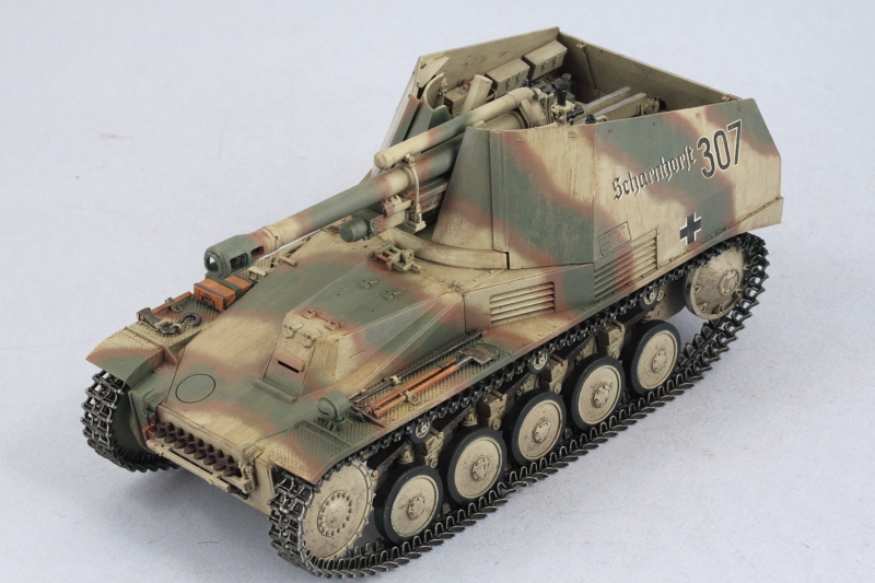
Completion 08-29-2010
Following on yesterday's footsteps, the final processes for the weathering stages were completed today.
First order of business was the application of a pin wash of roughly 90/10 Thinner/MM enamel Burnt Umber using a 10/0 brush to all the raised details and panel lines.

Since the previous washes and filters had removed much of the glossy surface, the pin wash "bloomed" in some places and the excess needed to be cleaned up. This was easily done with the same 10/0 brush and careful use of clean thinner to fine tune the result.

Next up the entire vehicle was given a coat of Testors MM Lusterless Flat in the spray-can to remove any remaining vestiges of gloss from the Future and to tie all the weathering in together. This was allowed to air dry for an hour or so and then the pigments were applied. I used a combination of Mig Pigments Rubble Dust, Europe Dust, Light Dust, and Dark Mud mixed together as dry powders. This was turned into a slurry/wet mixture by adding ordinary tap water with a touch of dish washing liquid soap to break the surface tension and the wet mixture applied liberally to the lower hull, tracks, and running gear with an old sable brush. The mixture was left to air dry which took about an hour or so.

I put on a dust mask to avoid breathing in the fine pigment particles and went to work removing excess pigment with a large round stiff bristled brush. The key here is to remove varying degrees of pigment depending on the surface in question, leaving for example more in place around the leaf springs and suspension but removing more on the wheels themselves, etc. I used some smaller square tip stiff bristled brushes as well for the tighter areas where needed.

Some additional fine tuning was done using both wet and dry cotton swabs until I had the result I was after.

That left one final detail...the installation of the radio antenna. This was accomplished with a small amount of CA gel applied to the base of the RB Models 2m brass antenna and then inserting it into the hole I'd pre-drilled earlier on in the assembly process.

The antenna was the painted with MM Non-buffing Metalizer Gunmetal and it was off to the photo-booth for the completed shots:


First order of business was the application of a pin wash of roughly 90/10 Thinner/MM enamel Burnt Umber using a 10/0 brush to all the raised details and panel lines.
Since the previous washes and filters had removed much of the glossy surface, the pin wash "bloomed" in some places and the excess needed to be cleaned up. This was easily done with the same 10/0 brush and careful use of clean thinner to fine tune the result.
Next up the entire vehicle was given a coat of Testors MM Lusterless Flat in the spray-can to remove any remaining vestiges of gloss from the Future and to tie all the weathering in together. This was allowed to air dry for an hour or so and then the pigments were applied. I used a combination of Mig Pigments Rubble Dust, Europe Dust, Light Dust, and Dark Mud mixed together as dry powders. This was turned into a slurry/wet mixture by adding ordinary tap water with a touch of dish washing liquid soap to break the surface tension and the wet mixture applied liberally to the lower hull, tracks, and running gear with an old sable brush. The mixture was left to air dry which took about an hour or so.
I put on a dust mask to avoid breathing in the fine pigment particles and went to work removing excess pigment with a large round stiff bristled brush. The key here is to remove varying degrees of pigment depending on the surface in question, leaving for example more in place around the leaf springs and suspension but removing more on the wheels themselves, etc. I used some smaller square tip stiff bristled brushes as well for the tighter areas where needed.
Some additional fine tuning was done using both wet and dry cotton swabs until I had the result I was after.
That left one final detail...the installation of the radio antenna. This was accomplished with a small amount of CA gel applied to the base of the RB Models 2m brass antenna and then inserting it into the hole I'd pre-drilled earlier on in the assembly process.
The antenna was the painted with MM Non-buffing Metalizer Gunmetal and it was off to the photo-booth for the completed shots:
-
Bill Plunk
- Posts: 1245
- Joined: Wed Sep 28, 2022 10:18 pm

