Dragon StuG III Ausf. F/8 Late Production (2014)

Bill Plunk
Posts: 1245
Joined: Wed Sep 28, 2022 10:18 pm

Dragon StuG III Ausf. F/8 Late Production (2014)

Post by Bill Plunk »

Build log for Dragon's 1/35 kit #6644 StuG III Ausf. F/8 Late Production w/Winterketten.

Image

This build will be finished as one of the 4 StuGs that saw service with StuG Battery 90 in North Africa with the 10 Pz. Div. between Jan-May 1943.

Image
Bill Plunk
Posts: 1245
Joined: Wed Sep 28, 2022 10:18 pm

WIP 06-22-14

Post by Bill Plunk »

Journeys always begin with a single step...and in this case the first one deals with the inevitable road wheels! I put together a short run of 16 links of the MK workable tracks to serve as a guide to ensure the sprockets and idlers were properly aligned and gapped so there wouldn't be any issues there. The idlers got their kit-supplied PE inner rims, the road wheel halves were removed from the sprues and their mold seams sanded down, and the return rollers assembled to kick things off. Not a dramatic first step but a first nonetheless! ;)

Image
Bill Plunk
Posts: 1245
Joined: Wed Sep 28, 2022 10:18 pm

WIP 06-29-2014

Post by Bill Plunk »

Progress on the StuG resumed as usual with the bulk of the attention going towards Step 2 which deals with the torsion bar suspension and various details for the hull sides. There are a couple of instruction pit-falls to watch out for, the first is that the angled hull nose plate, D11, is shown installed in the step but without a number call-out. It's important to install this part first before you add the hull towing eye extensions (parts B13/B14) as they interact with D11 in terms of fit and placement. The second pitfall is parts Q38, they are really Q22 as you need four of them and Q38 is a single part, the shovel!

The neat thing about the way Dragon designed the suspension is that the middle four road wheels on either side can be made workable if you remove the mounting pin that the swing arms attach to on the hull plates. These are easily clipped off and sanded smooth to allow the suspension to work, always a plus when using workable tracks like I am but also to help ensure that the arms will all sit level on both sides. The front and rear wheels are fixed in position however due the shock absorbers being all one-piece, so no luck there.

There is another small thing to point out that is actually part of Step 1. The idler mounts take a half-moon shaped part, B2/B3, that matches up with the rear hull plate to create the full idler tension housing. It's virtually impossible to install this correctly as called for in Step 1, so I waited until I had the plate installed to add those along with the idler mounts themselves. The final drive housings were also added but the sprockets left off to make it easier to paint and detail them separately.

Image

Steps 3 and 5 deal with the rear hull plate details and the air vent screens and deflectors. The sharp eyed among you will notice that the rear plate is already installed in the above pic. That's due to the fact that the plate needs to interact with the idler mounts, so I added the engine exhausts to the plate, installed it into position, then added the four braces for it to flex out the rear part of the hull properly. Once that was dry, then the rest of the rear plate details were added. My pic of the Africa StuG shows it had the rear towing pintle, so that option was used. Kit supplied PE screen was installed and then the deflector pieces added.

Image

Next up will be starting work on the fenders and casemate structure!
Bill Plunk
Posts: 1245
Joined: Wed Sep 28, 2022 10:18 pm

WIP 07-04-2014

Post by Bill Plunk »

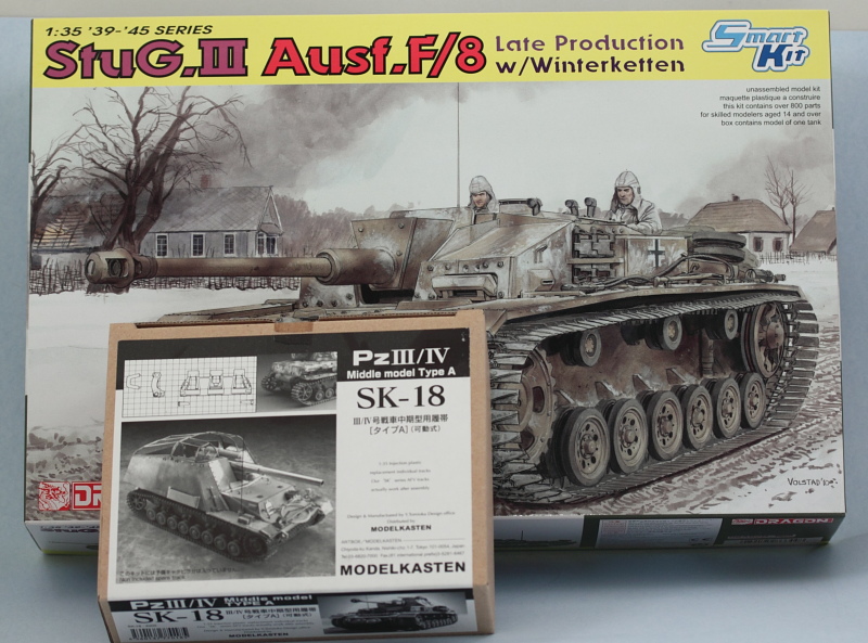
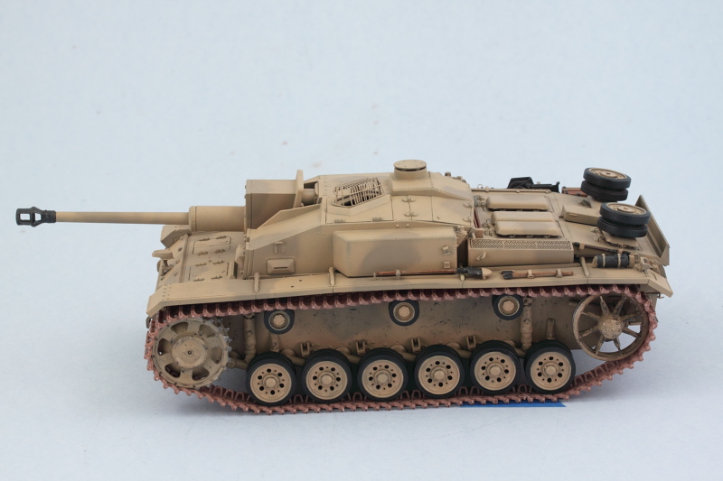
I've made a lot of progress as a result of the 4th of July holiday and apologize for the large number of photos in advance. This is driven more by how Dragon designed the way all of the upper hull components come together than my desire to torture you with a ton of pics! ;)

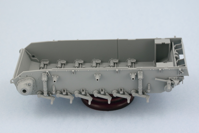
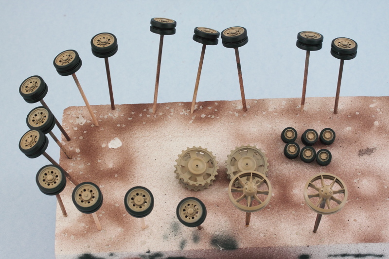
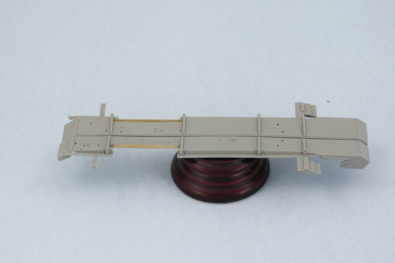
First I had to study the instructions and figure out what goes where. To that end, I started on the fenders as called for in Step 6 and got them all cleaned up and their braces added but left off all the tools and small parts for later.

Image

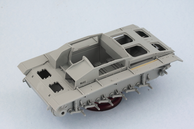
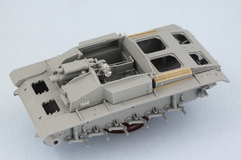
If you follow the instruction order of things (not recommended!), Dragon would have you wait until the very end step to install the casemate, interior, and engine deck together as a single module along with the fenders and glacis plate. This would require a level of precision in terms of how all the parts go together that would be hard to achieve in my view so I did things a little different. I started first with cleaning up the glacis, casemate shell, and engine deck platforms and did a mock-up test fit with all the components to see how they would go together. Everything plays nice, but the fenders have supports that slide under the glacis, the casemate depends on the fender supports to site correctly, and the engine deck has to trap the edges of the fenders just right...so waiting until the end to achieve all this is risky to say the least.

Image

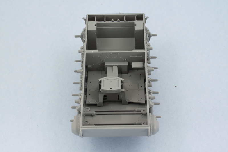
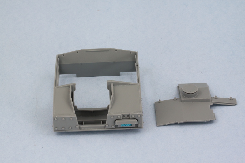
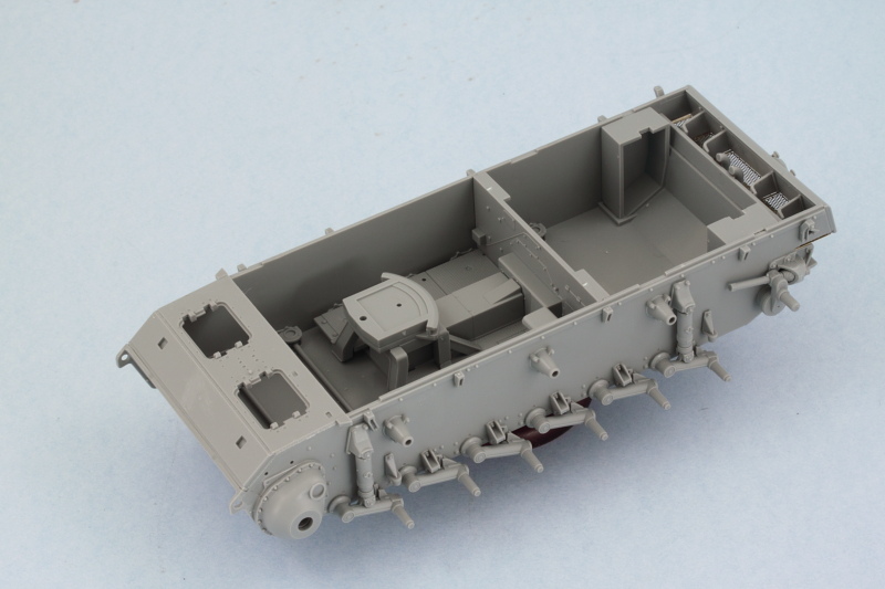
So far so good, but the other question remained about how to best deal with the interior and gun mount. The fighting compartment bulkhead slides into slots in the lower hull and this in turn helps 'spread' the top of the hull to the right width. So rather than attach it to the hull, I used the hull to place it at the proper spot and then carefully glued it in place with the interior floor but didn't glue the floor into place yet. I did assemble the base of the gun mount from Step 13 and installed that into the floor.

Image

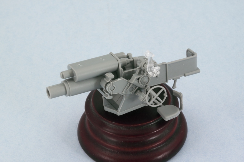
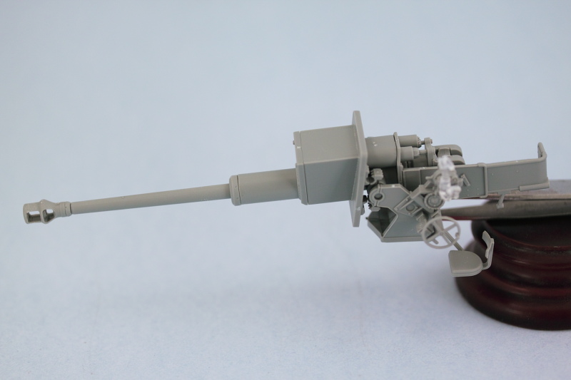
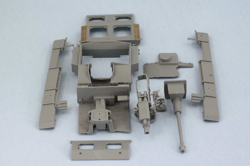
The rest of Step 13 assembles the gun mount and all of its details.

Image

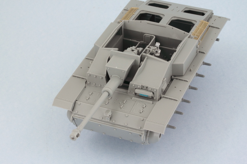
And a test fit with the floor mount shows it will sit just fine...but you can't secure it in place yet as the way it interacts with the casemate requires a little bit of contortionism to achieve.

Image

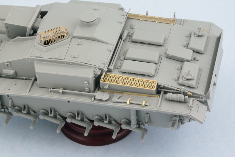
A simple test fit with the casemate along with its roof plate ensured that the alignment of the gunner's periscope sits properly and lines up with the opening in the hatch.

Image

Step 14 assembles the main gun barrel and block mantlet. The block mantlet and barrel can't be installed until the casemate is in position but you need the end of the barrel to line up properly with the D-shaped opening in the gun recoil housing. To achieve that, I slid the block mantlet over the housing as a dry-fit and then glued the barrel and components in one by one until the full thing was built and all aligned correctly. After the glue set, the mantlet and beyond portion was removed so it could be installed separate from the mount.

Image

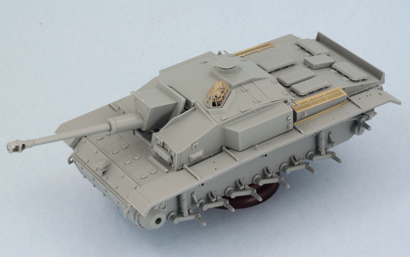
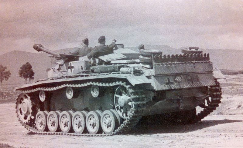
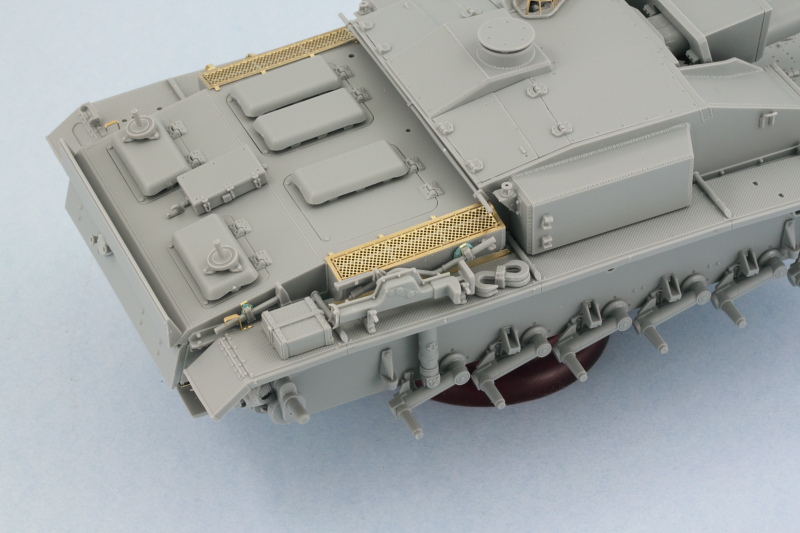
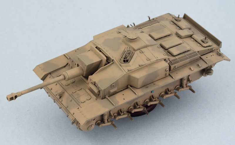
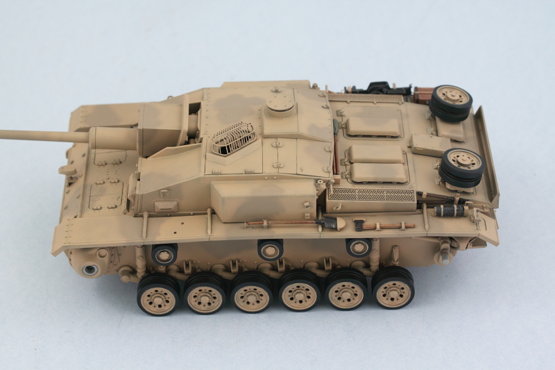
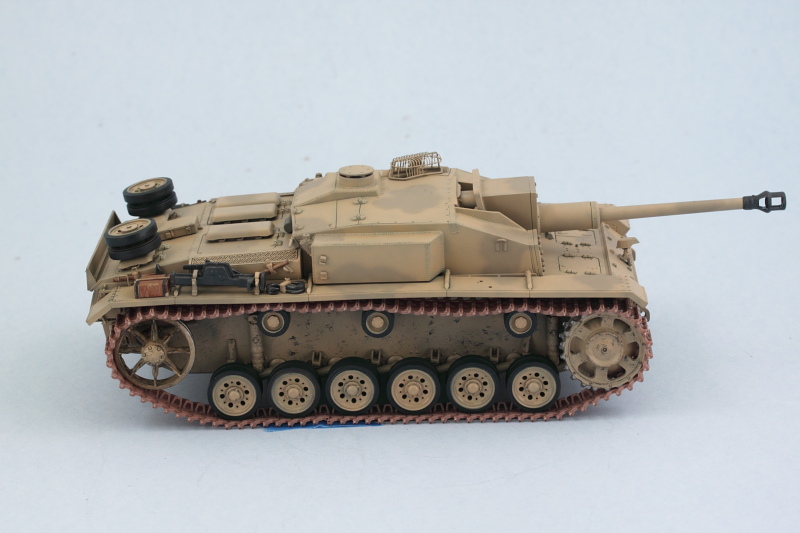
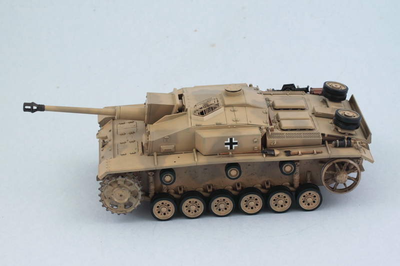
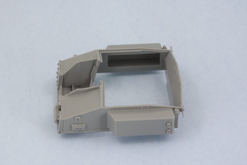
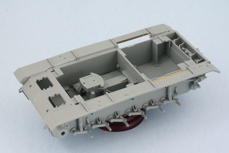
This next part is best described as bringing all the other parts together to form the upper hull. I returned to Steps 7 and 8 and added most of the details there to the casemate in the form of the driver's plate and add-on plates. It's worth noting here that there's no 'M' sprue of clear parts, those are on a 'V' sprue, so bear that in mind. I'm opting not to install the roof mounted MG since that's a feature that wasn't fitted until early 1943 and was only done to some F/8s.

Image

Step 9 adds the side panniers to the casemate along with other details. Since I'm closing all the hatches, I didn't bother with assembling the radio gear and installing it but will add them to the spares bin for possible use on future projects. Same thing for the 'rabbit ears' periscope, this is only needed if the commander's hatches are going to be open. I drilled out the antenna mounts to take 2m brass RB antennas later on.

Image

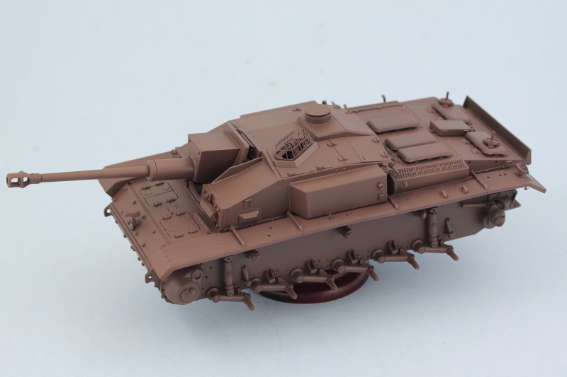
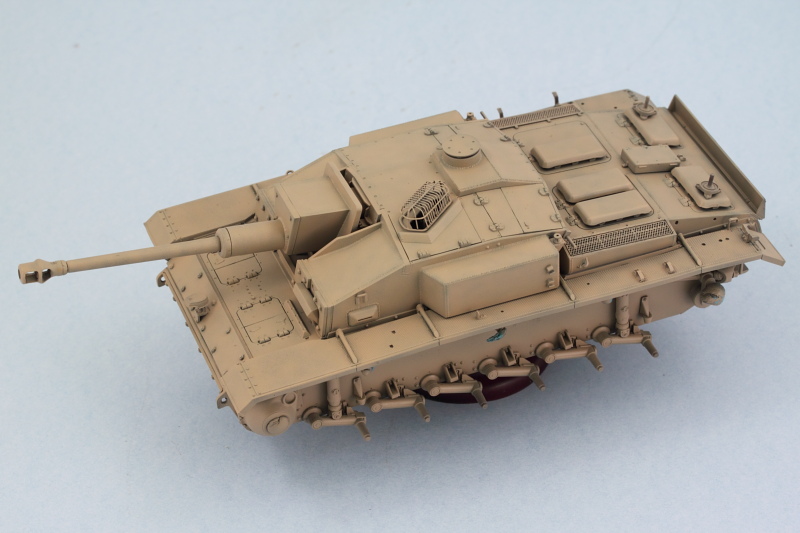
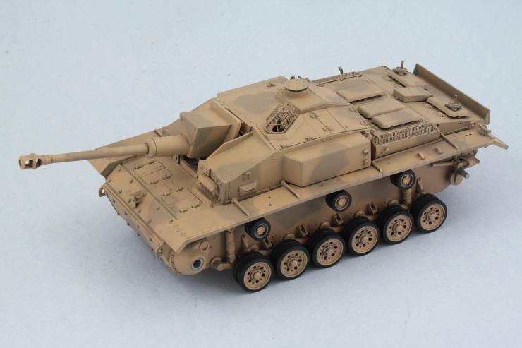
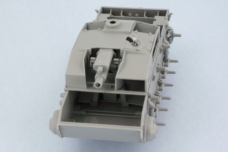
That brought me to this stage in the build in terms of components that all have to work together to get the upper hull together...as you can see, it's a lot!

Image

And since the photos will tell the story...here's how I determined was the best way to get it all together:

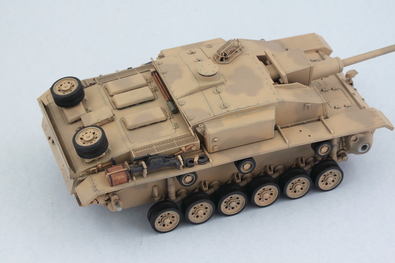
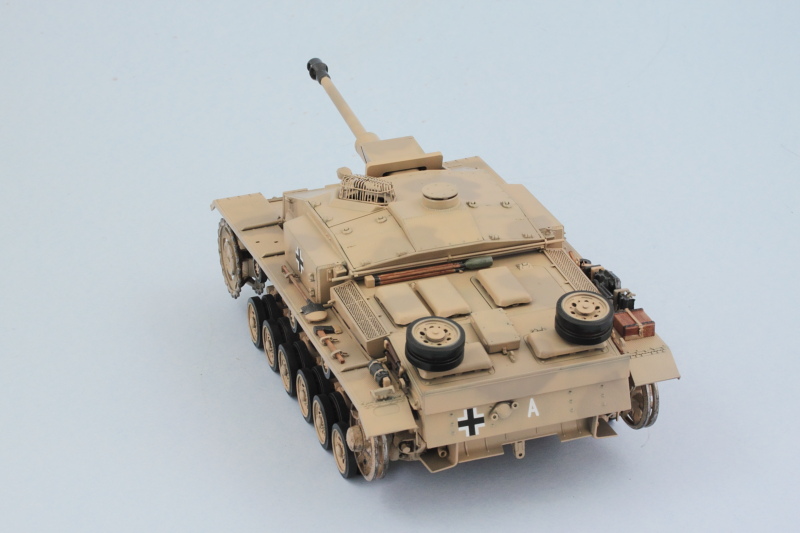
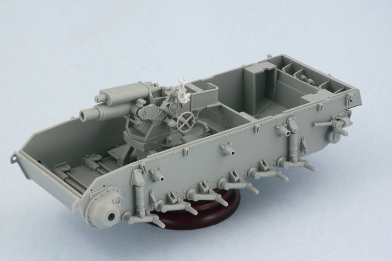
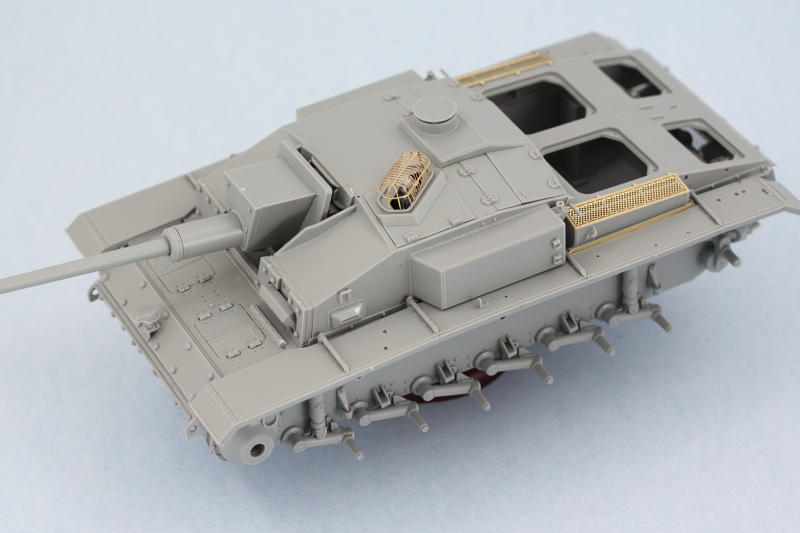
#1 Install the glacis and interior floor and bulkhead to spread the hull to the right width.

Image

#2 Fenders come next, using glue only at the front and middle edges to secure it in place. I did have to modify the 'notches' at the rear in terms of using a square needle file to cut them deeper to allow them to fit correctly.

Image

#3 Add the casemate and gun mount next.

Image

#4 Install the engine deck, it's a tight fit, almost a snap fit. I only needed to use slight finger pressure at the very rear to get it close up correctly with the fenders and hull edge.

Image

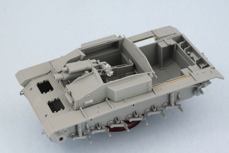
#5 Finally install the block mantlet and gun in place. This is best done after completing Step 12 which adds all the details to the glacis plate including the access hatches and Notek light. I added the bolt-on armor for the hull nose as well now that I could get it lined up properly with everything.

Image

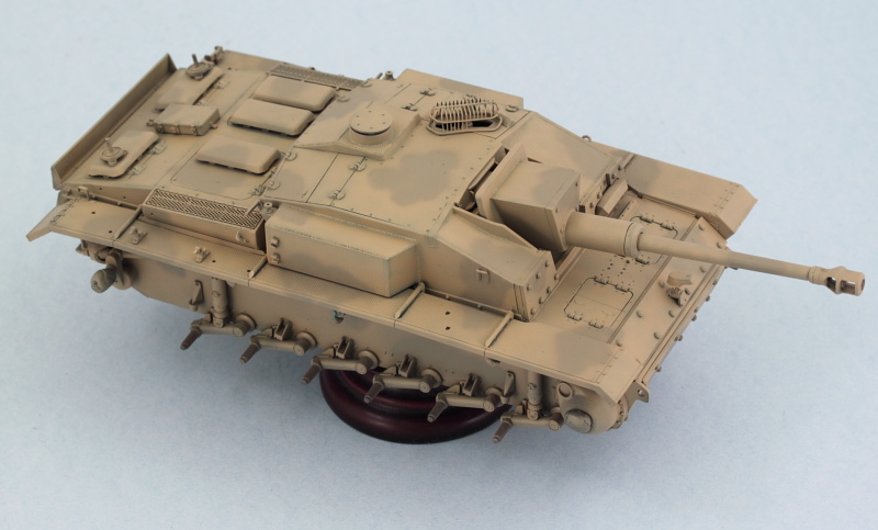
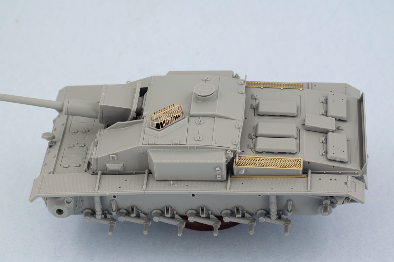
Step 10 came next, adding all the hatches in the closed position to the casemate roof. Part Q34 from Step 16 is used to trap the gun mount into place and complete the roof assembly. I used the pre-formed brass 'cage' for the sight cover as it's got the best in-scale appearance vs. the styrene cage option also included. Unfortunately I forgot that I intended to leave that hatch loose to make it easier to paint it and the scope and ended up gluing it in place without thinking. ;)

Image

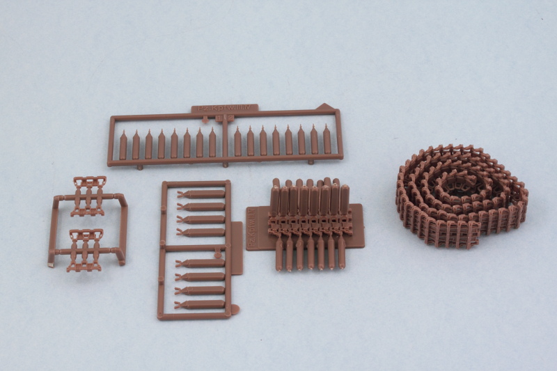
Rounding things out, I completed Step 11 that installs all the access hatches for the engine deck. The instructions don't call out the separate hinge parts, G40, so you have to hunt for them on the sprues to figure out where they are. The spare track tail gate from Step 16 was also added.

Image

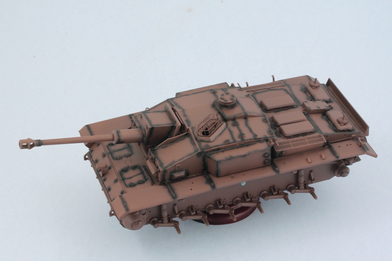
Next up will be attending to some of those fender details before this one heads over to the paint booth.

Image
Bill Plunk
Posts: 1245
Joined: Wed Sep 28, 2022 10:18 pm

WIP 07-06-2014

Post by Bill Plunk »

Spent some more time working on the details but didn't quite get to the painting stage. All the tools for the fenders were cleaned up and test fit in their various locations and Griffon PE handles added to the various clamps that had molded-on handles and full clamps replacing the ones for the axe. The placement of items on the right fender is particularly tricky as the 'foot' of the jack is too long and had to have its stub that goes inside the body trimmed back to allow it to sit at the right length.

Image

Image

Work continues on the workable tracks and then it will be time to prep for the painting to begin.
Bill Plunk
Posts: 1245
Joined: Wed Sep 28, 2022 10:18 pm

WIP 07-17-2014

Post by Bill Plunk »

Finally managed to get enough time in on this one to warrant an update! I've been working on the 'standard' workable MK tracks to take the place of the kit-supplied Magic Track winterketten type. The MK tracks assemble 8 links at a time via a jig included in the set with separate guide horns and track pins. The pins twist off after the glue has set while the handles on the guide horns are easily removed with sprue cutters.

Image

Typically on a Pz III/StuG III vehicle the number of links per side is 92-93 but I always wait until after I've got the road wheels on to complete the full runs. For now both runs are at 90 links per side until I can test the right number needed for sag/fit. I also assembled the spare run of 14 links needed for the rear 'tailgate' area.

Image

Now it's time to move on the paint work!
Bill Plunk
Posts: 1245
Joined: Wed Sep 28, 2022 10:18 pm

WIP 07-20-2014

Post by Bill Plunk »

Started in on the paint work today to get this one moving ahead in that department. First order of business is a primer coat of Model Master enamel Italian Dark Brown.

Image

Also started in on the road wheels, return rollers, sprockets, and idlers. Same prime coat treatment and the rubber portions were airbrushed with MM enamel Gunmetal.

Image

More to come of course!
Bill Plunk
Posts: 1245
Joined: Wed Sep 28, 2022 10:18 pm

WIP 07-22-2014

Post by Bill Plunk »

More progress in the paint department to report! After letting the primer coat sit for a day, I used some MM Flat Black to create some pre-shading.

Image

Basecoat came next. Since this one is getting the 2nd Tropen scheme ordered in March '42 (2/3 RAL 8020, 1/3 RAL 7027), I laid down the first color using MM Afrika Braun in very thin passes to build it up over the primer/pre-shade effort.

Image

At the same time, the wheels-on-a-stick got their hubs done using a draftsman's circle template to mask the rubber wheels.

Image

Next came the camo pattern using MM Afrika Dunkelgrau.

Image

Image

Rounding things out, the wheels and return rollers were glued in place on the suspension so that it could get up on its feet for the next stages. The workable torsion bars are doing their job nicely. Everything sits level and no 'floating' wheels.

Image

Next up will be working on the rest of the exterior details.
Bill Plunk
Posts: 1245
Joined: Wed Sep 28, 2022 10:18 pm

WIP 07-26-2014

Post by Bill Plunk »

Managed to get all the on-board equipment squared away over a couple of sessions of hand detailing for the various parts. For metal portions, I used a combination of MM non-buffing Metalizer Gunmetal and a light dry-brushing of MM enamel Steel. For the wood portions, I used a base of 50/50 Dunkelgelb/Light Gray followed by a thin wash of MM enamel Leather and some burnt umber artist pastels to provide some variation. I also opted to detail the fire extinguisher and jack in panzer gray to add a little color in those areas on the fenders as well. All the tool clamps were detailed with their necessary colors to match the camo scheme depending on where they installed on the vehicle.

Then it was time to fit it all in place along with the spare road wheels on the engine deck. The tool arrangement on the right fender is very tight and it's critically important that the jack be positioned just right in relation to the block and S-hooks in particular, so the careful work done earlier in test fitting paid off.

Image

Image

Next up will be paying some attention to the lower hull and suspension as a 'pre weathering' step and getting the tracks ready for paint.
Bill Plunk
Posts: 1245
Joined: Wed Sep 28, 2022 10:18 pm

WIP 07-28-2014

Post by Bill Plunk »

Worked on the tracks and suspension a bit in preparation for the weathering stages later on. I created some scuffing/chipping by stippling some Panzer Schwarzgrau on the hull and sprocket and idler. The contact surfaces on the idler and the sprocket teeth were treated to some non-buffing Metalizer Steel followed by some dry-brushed Burnt Umber to create their look. A test fit with the MK runs showed that 93 links per side on both side did the trick just right for sag.

Image

Image

I also used a 10/0 pointed brush to paint the gunner's sight with some MM non-buffing metalizer Gunmetal through the birdcage, then touched up the exterior of the cage so it once more matched the hull. Laid down a sealing coat of acrylic Future floor polish, let that air dry for about an hour, then added the simple vehicle markings. The reference photo showed an 'A' on the rear hull plate, so I added that by cutting one off the kit-supplied 'name' decals as an added touch.

Image

Image

Applied a 2nd coat of Future over the decals after they had thoroughly set to seal them in, will let that cure for a good 24 hours before starting in on the filters and weathering.
Post Reply