Bronco Pzkpfw I Ausf F (VK 18.01) (2014)
-
Bill Plunk
- Posts: 1245
- Joined: Wed Sep 28, 2022 10:18 pm
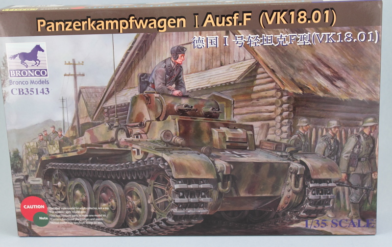
Bronco Pzkpfw I Ausf F (VK 18.01) (2014)
Build log for Bronco's 1/35 kit 35143 Pzkpfw I Ausf F (VK 18.01).
-
Bill Plunk
- Posts: 1245
- Joined: Wed Sep 28, 2022 10:18 pm
WIP 03-23-2014
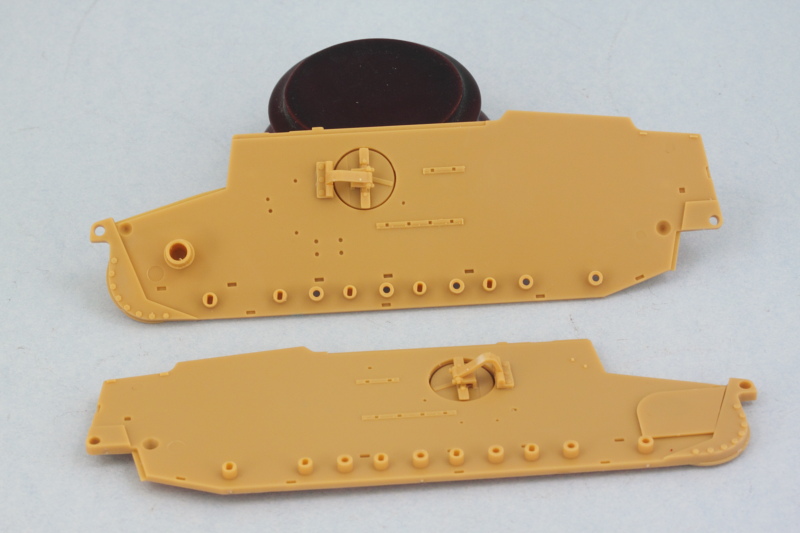
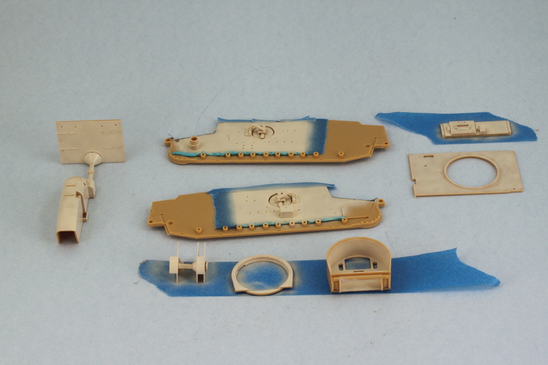
Got things off and rolling on this build by doing things a little differently. Bronco includes a lot of detail for the fighting compartment interior and also constructs the hull out of multiple panels vs. providing a single 'tub'. Ordinarily I wouldn't be that big of a fan of this approach but with all the interior detail and how tiny this vehicle is, this is actually a plus on this particular build as it lets you work with each panel separately. So, the first order of business was to prep all the major hull panels and the compartment floor and do a mock-up using masking tape to hold things together to ensure there weren't going to be any surprises along the way.
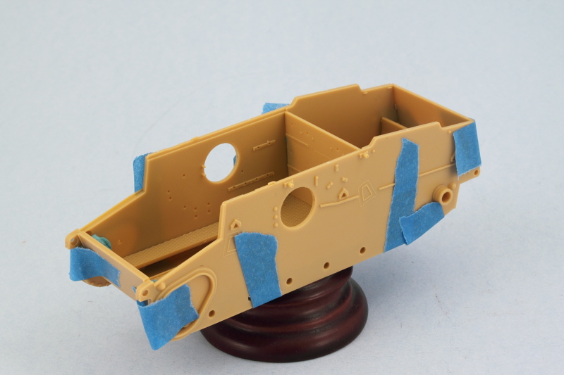
No major issues to report but it will be fun installing all the suspension torsion bars and getting all these elements together permanently once the detailing and paint work is finished, but we'll cross that bridge much later on! Because many of the interior components are made up of multiple parts, some tiny, some that require fit with other small parts, etc., I bounced around between various steps while glue set up to try to make the most of my available time.
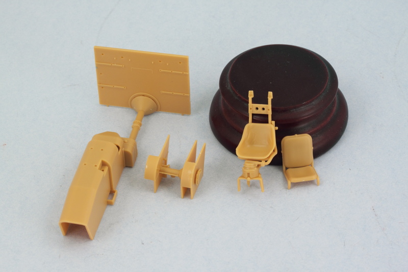
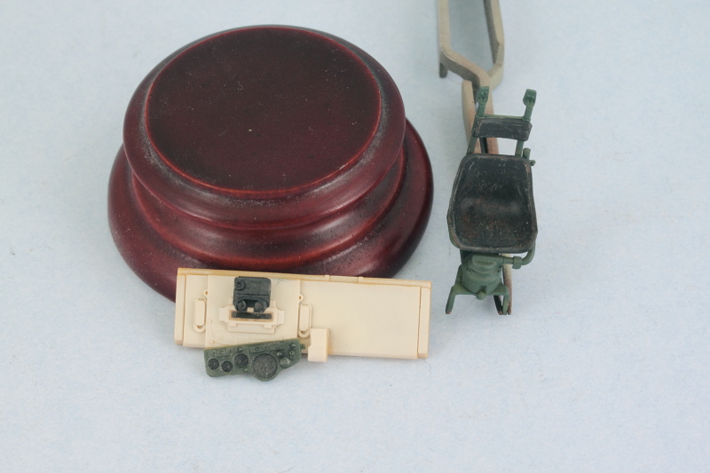
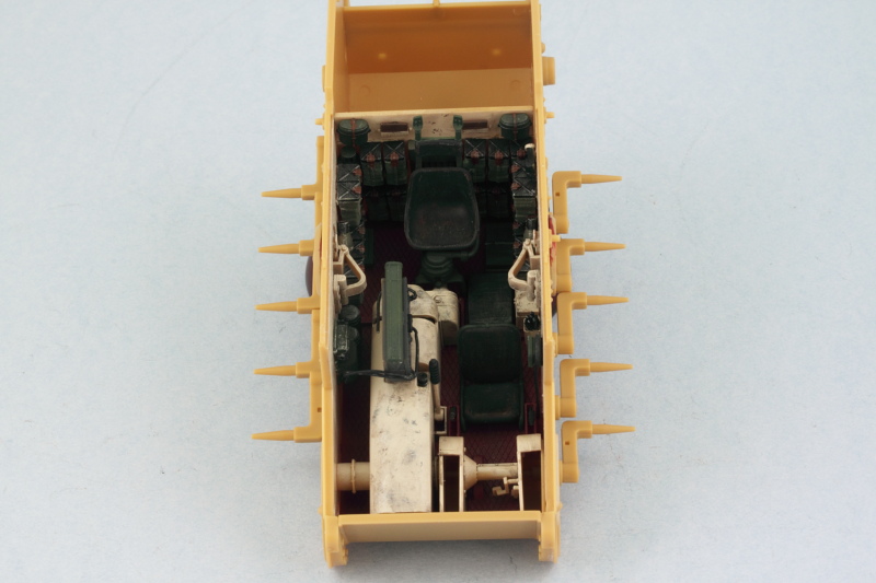
Taking advantage of the hull mock-up situation, I assembled the various transmission and drive-shaft components and also connected the firewall to the large transmission cover housing since those are initially separate pieces. The alignment here is key as it drives (no pun intended!) not only how the firewall sits but also where the commander's seat lines up and how everything interacts at the front of the hull. No real margin for error here either given how tightly packed everything is on the inside.
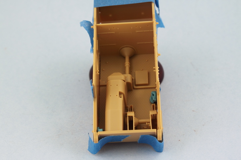
Once the glue had set on the transmission and firewall combo, I undid the mock-up and restored everything back to its panel parts for easier handling. The tiny driver's pedals were added and the driver's and commander's seats assembled. The commander's seat is a multi-part and very delicate 'free standing' assembly...so lots of care needed here to get it all together and aligned correctly. I left the headrest and main seat cushion separate for now to make it easier to paint them and will add them later.
One of the really nice features of the kit IMHO is the inclusion of workable crew side escape hatches. Yes, that's right, fully workable...but you do have to be very careful with the assembly and where you put the glue, but in the end if you do it right, they will work just like on the actual vehicle. Only downside is that they tend to want to swing open all the time, so once the glue had set on the hinge arms, I'm using small blobs of blue-tack poster putty on the inside surfaces to keep them 'closed' while work continues.
Next up will be devoting some attention to the rest of the gear details that go in this area like the radios, numerous ammo sacks for the turret MGs, crew equipment, etc.
No major issues to report but it will be fun installing all the suspension torsion bars and getting all these elements together permanently once the detailing and paint work is finished, but we'll cross that bridge much later on! Because many of the interior components are made up of multiple parts, some tiny, some that require fit with other small parts, etc., I bounced around between various steps while glue set up to try to make the most of my available time.
Taking advantage of the hull mock-up situation, I assembled the various transmission and drive-shaft components and also connected the firewall to the large transmission cover housing since those are initially separate pieces. The alignment here is key as it drives (no pun intended!) not only how the firewall sits but also where the commander's seat lines up and how everything interacts at the front of the hull. No real margin for error here either given how tightly packed everything is on the inside.
Once the glue had set on the transmission and firewall combo, I undid the mock-up and restored everything back to its panel parts for easier handling. The tiny driver's pedals were added and the driver's and commander's seats assembled. The commander's seat is a multi-part and very delicate 'free standing' assembly...so lots of care needed here to get it all together and aligned correctly. I left the headrest and main seat cushion separate for now to make it easier to paint them and will add them later.
One of the really nice features of the kit IMHO is the inclusion of workable crew side escape hatches. Yes, that's right, fully workable...but you do have to be very careful with the assembly and where you put the glue, but in the end if you do it right, they will work just like on the actual vehicle. Only downside is that they tend to want to swing open all the time, so once the glue had set on the hinge arms, I'm using small blobs of blue-tack poster putty on the inside surfaces to keep them 'closed' while work continues.
Next up will be devoting some attention to the rest of the gear details that go in this area like the radios, numerous ammo sacks for the turret MGs, crew equipment, etc.
-
Bill Plunk
- Posts: 1245
- Joined: Wed Sep 28, 2022 10:18 pm
WIP 04-06-2014
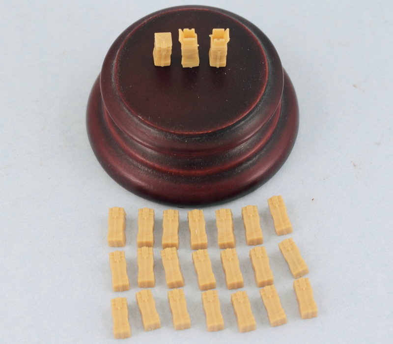
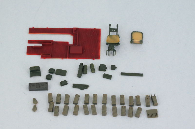
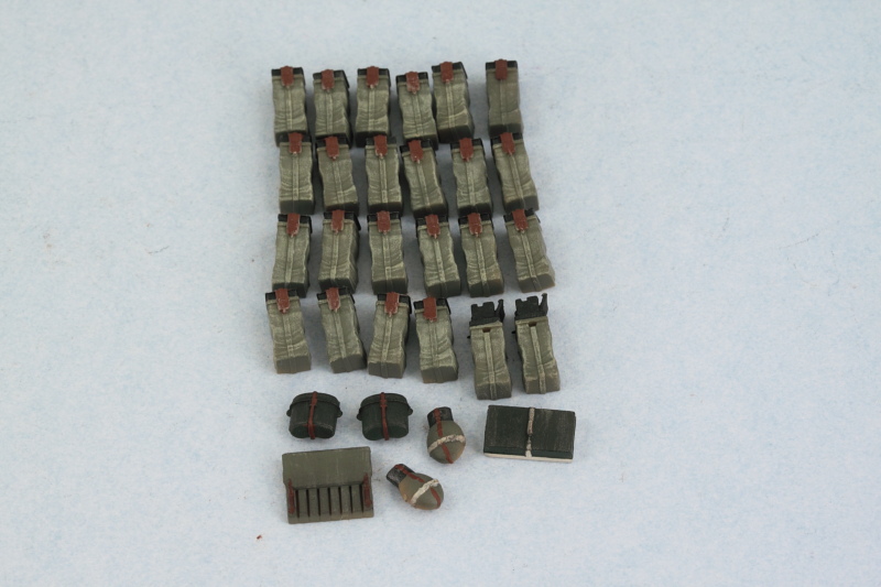
Managed to get in some time on the interior bits and details on this pocket-Tiger. Bronco follows their usual penchant for tiny parts and there's a lot going on inside this little guy. First up were the 22 'standard' Gurtsack ammunition bags plus 2 'in use' bags for the twin MGs in the turret. These had 2 or 3 sprue contact points each that had to be cleaned up so was a case of '22 Gurtsacks on the sprue, 22 Gurtsacks on the sprue...cut one free and clean it up, 21 Gurtascks on the sprue!' type of effort.  Worth it though as they have very nice molded details and will be painted with the AB when the time comes to avoid smothering some of the finer details.
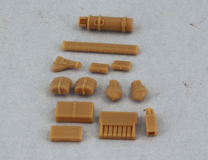
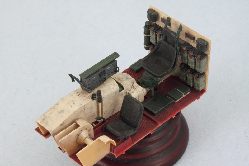
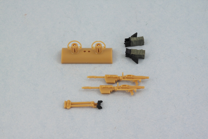
Next up were all the other different interior gear items that need to be painted/detailed separately before installation. The FE, the spare barrels case, the First Aid kit, crew mess kits and canteens (and also the gas mask containers, which I noticed I forgot while taking this pic!), the MP40 ammo case, the flare pistol and flare round holder, and the 'Gedore' tool box that goes on the compartment floor.
Little guy needs its comms gear as well, so the radio receiver and transmitter were assembled (special note, the back is hollow so if you plan to show the right side escape hatch open, this will need to be blanked off), and some holes drilled out with a #76 finger drill to take some wiring later on. Power transformer boxes and intercom box for the driver were also assembled and drilled out where appropriate.

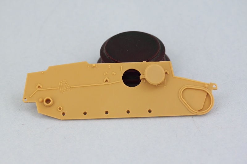
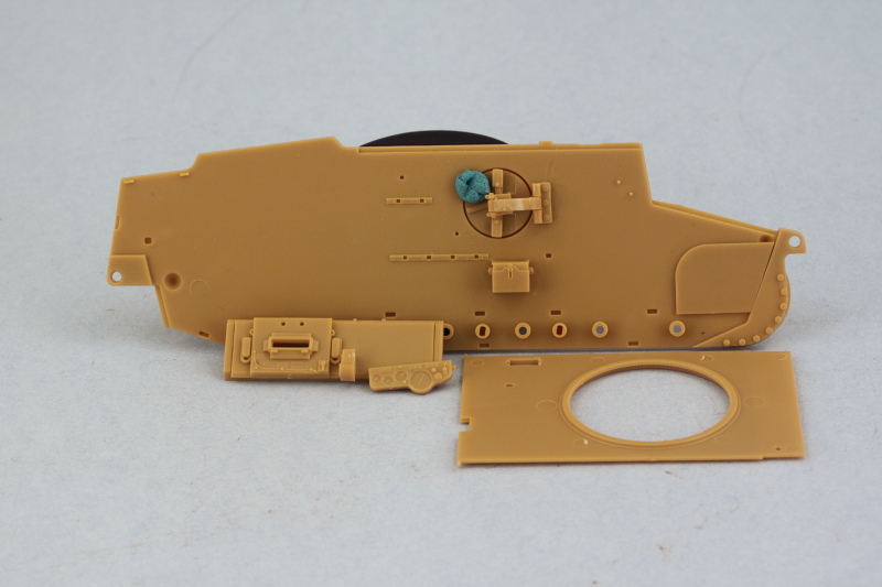
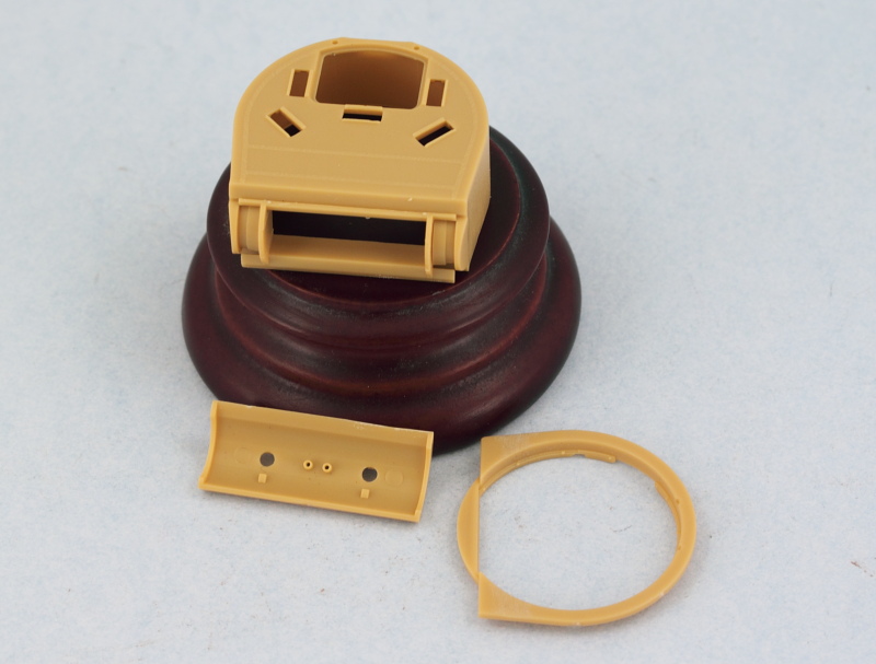
Also took care of some other small details like the small box on the left side below the escape hatch and I assembled the driver's front hull plate. The gauge panel mounts underneath it but I'm keeping it separate for now to make it easier to detail/paint and also to be sure it's lined up properly since it has to fit just so between the transmission housing and the hull glacis plate. The hull roof plate was also prepped for paint although most of it won't be seen of course once installed in position.
Next up was the turret. Due to the size of the fully-detailed MGs, you have to install the base of the mantlet into the turret front and then install the MGs from behind through the base and into the mantlet. That's going to be real fun I can tell, but will deal with that later. Mounts and mantlet base were installed so that the guns can elevate. The fit is kind of loose so I suspect that I will be gluing that in place later on once the weight of the guns is added and the external mantlet installed. External mantlet portion was prepped for paint on its inner surface since some of it will still be visible through the open commander's hatch and I don't want bare plastic peeking in around the edges inside. Last but not least, the turret base was prepped for paint as well to round things out.
So that means next up is flinging some paint on the interior!
Next up were all the other different interior gear items that need to be painted/detailed separately before installation. The FE, the spare barrels case, the First Aid kit, crew mess kits and canteens (and also the gas mask containers, which I noticed I forgot while taking this pic!), the MP40 ammo case, the flare pistol and flare round holder, and the 'Gedore' tool box that goes on the compartment floor.
Little guy needs its comms gear as well, so the radio receiver and transmitter were assembled (special note, the back is hollow so if you plan to show the right side escape hatch open, this will need to be blanked off), and some holes drilled out with a #76 finger drill to take some wiring later on. Power transformer boxes and intercom box for the driver were also assembled and drilled out where appropriate.
Also took care of some other small details like the small box on the left side below the escape hatch and I assembled the driver's front hull plate. The gauge panel mounts underneath it but I'm keeping it separate for now to make it easier to detail/paint and also to be sure it's lined up properly since it has to fit just so between the transmission housing and the hull glacis plate. The hull roof plate was also prepped for paint although most of it won't be seen of course once installed in position.
Next up was the turret. Due to the size of the fully-detailed MGs, you have to install the base of the mantlet into the turret front and then install the MGs from behind through the base and into the mantlet. That's going to be real fun I can tell, but will deal with that later. Mounts and mantlet base were installed so that the guns can elevate. The fit is kind of loose so I suspect that I will be gluing that in place later on once the weight of the guns is added and the external mantlet installed. External mantlet portion was prepped for paint on its inner surface since some of it will still be visible through the open commander's hatch and I don't want bare plastic peeking in around the edges inside. Last but not least, the turret base was prepped for paint as well to round things out.
So that means next up is flinging some paint on the interior!
-
Bill Plunk
- Posts: 1245
- Joined: Wed Sep 28, 2022 10:18 pm
WIP 04-13-2014
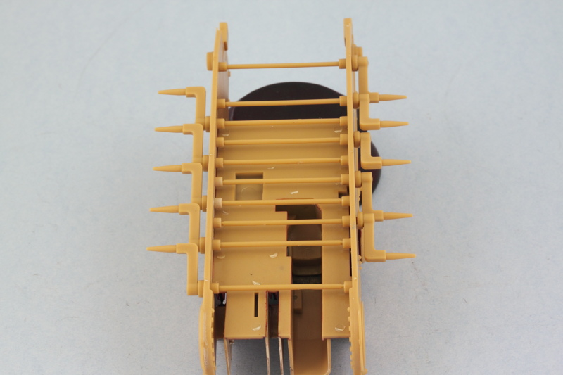
While the last update dealt with the interior parts, today's efforts focused on the workable tracks. Bronco provides an excellent set of workable tracks in the kit, so no need to resort to my usual trusty MK replacement strategy. The kit calls for 66 links per side but until I get the hull built and suspension in place, I only worked on 60 links to be safe. The pins for the links are molded a little funny...to save on total sprue space I guess, some of the pins are separate along the sides of the sprue while the middle run has pins in a double set. The tracks are handed, so it's important to keep track of which pins are which. Using the kit-provided jig, I assembled the runs one link at a time, cutting the pins free of the sprues and using the nub as a 'handle' to insert the pins then cutting it away after the glue had started to set on the head of the pin.
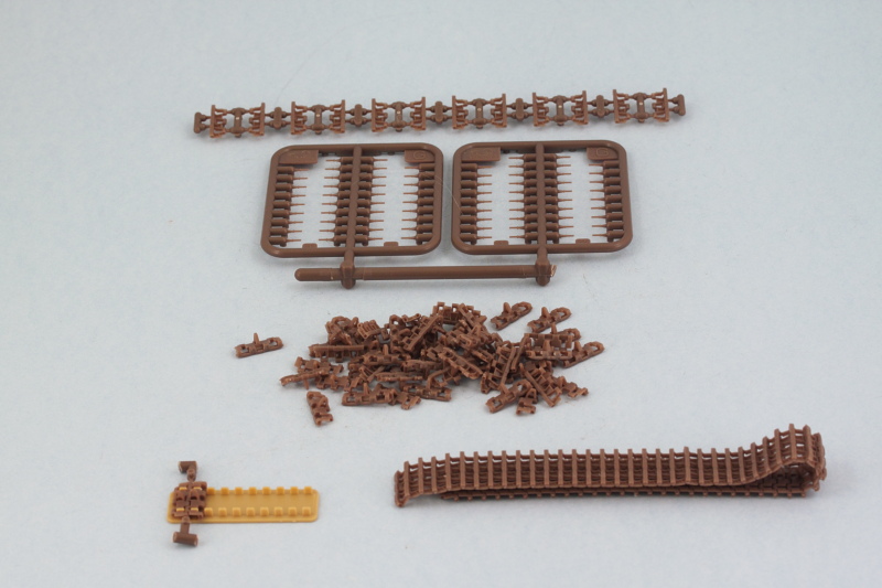
120 links later, we have two nice workable runs to play with in the future.
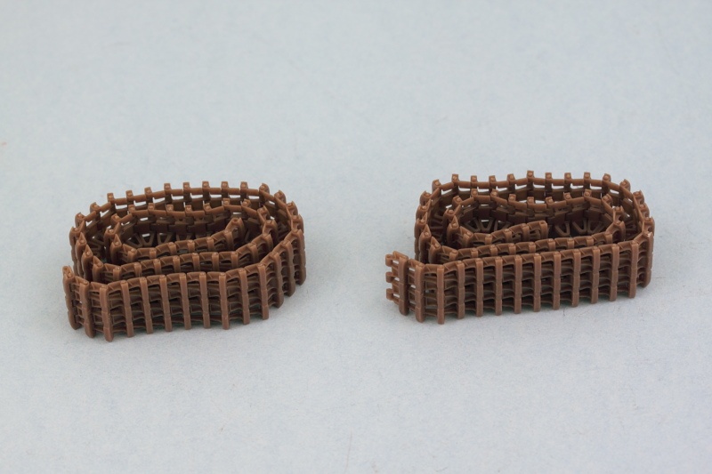
May not look like much, but this is a major step in the construction 95% complete until the suspension is available to test the number needed for the right sag/tension arrangement.
120 links later, we have two nice workable runs to play with in the future.
May not look like much, but this is a major step in the construction 95% complete until the suspension is available to test the number needed for the right sag/tension arrangement.
-
Bill Plunk
- Posts: 1245
- Joined: Wed Sep 28, 2022 10:18 pm
WIP 04-16-2014
In the spirit of making lemonade out of lemons, since I had some unexpected free time today, I decided to put in some more on the Pz I. I couldn't be sure of enough time for painting so decided to work on the road wheels and other running gear instead.
First up were the sprockets and idlers. The front half of the sprocket as very delicate contact points and no real positive locater aids other than getting the teeth lined up properly, so you have to be careful with it. I glued them together and used the track runs assembled earlier to help 'hold' the halves in the right alignment with each other until the glue had set up. I also made a slight modification to the final drive housings in the form of a length of styrene rod glued over the sprocket mount pin to 'trap' it in place and leave it able to rotate freely later on. The idlers went together without any issues.

Then it was time to deal with the road wheels. At first the instruction diagram in Step 9 is a little confusing as it seems to indicate that you need to build two different types of the 'paired' wheels but in reality they are all the same, just Bronco used some slightly different parts numbers I guess due to the way the sprues were laid out. In the end you get the 6 paired road wheels you need, 3 per side, and that's what counts! The two interleaved wheels per side had their halves cleaned up but left unassembled now so they can be painted and installed later once the suspension gets installed.

Have to seize the opportunities that come your way even if unexpected!
First up were the sprockets and idlers. The front half of the sprocket as very delicate contact points and no real positive locater aids other than getting the teeth lined up properly, so you have to be careful with it. I glued them together and used the track runs assembled earlier to help 'hold' the halves in the right alignment with each other until the glue had set up. I also made a slight modification to the final drive housings in the form of a length of styrene rod glued over the sprocket mount pin to 'trap' it in place and leave it able to rotate freely later on. The idlers went together without any issues.
Then it was time to deal with the road wheels. At first the instruction diagram in Step 9 is a little confusing as it seems to indicate that you need to build two different types of the 'paired' wheels but in reality they are all the same, just Bronco used some slightly different parts numbers I guess due to the way the sprues were laid out. In the end you get the 6 paired road wheels you need, 3 per side, and that's what counts! The two interleaved wheels per side had their halves cleaned up but left unassembled now so they can be painted and installed later once the suspension gets installed.
Have to seize the opportunities that come your way even if unexpected!
-
Bill Plunk
- Posts: 1245
- Joined: Wed Sep 28, 2022 10:18 pm
WIP 04-20-2014
I suppose it's fitting that on Easter Sunday some paint was allowed to fly!
Spent the day working on the bulk interior painting to get things ready to move into the detail and assembly stage for that area. First up was an airbrush treatment of Model Master enamel Panzer Interior Buff to all the applicable hull areas and units. Because I hate to scrape paint, I used a combination of masking tape and poster blue-tack putty to mask off the hull floor and side joins to make life a little easier when the hull comes together down the road.
Ordinarily it's not worth the trouble to airbrush small detail parts but since the interior has so many, I decided this time around that the airbrush would be the better method vs. hand painting. The compartment floor was airbrushed with a custom mix of 'primer red' that I keep around but don't quite remember the exact mix ratio on...I do know it contains Insignia Red, Flat Black, and a touch of Light Gray...and a little bit goes a long way!
Radio received some Gunship Gray, the seat mounts and other odd bits of gear were airbrushed with Khaki. The Gurtsacks and crew canteens are largely made of cloth or have cloth covers so I used a different shade for them, trying out some Faded Olive Drab as their base color, and have to say I was happy with the shade tone that produces.
This will all get the chance to cure before the next round of detail painting and the weathering process begins on the interior. Hope everyone had a Happy Easter!
-
Bill Plunk
- Posts: 1245
- Joined: Wed Sep 28, 2022 10:18 pm
WIP 04-27-2014
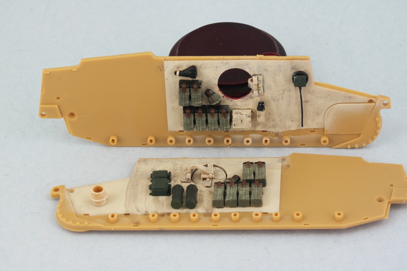
The devil's always in the details and that's where this session's attention focused on. Continuing on from last week, I went to work hand detailing all the various bits of gear that go into the fighting compartment interior. First up were the 24 ammo sacks, the MP40 ammo pouch, the canteens, mess tins, and the first aid box for the floor. Bronco provides some excellent molded-in 'cloth' detail to the ammo sacks so I dry-brushed some of my 50-50 Light Gray/Panzer Dunkelgelb custom mix that I keep around for three-tone camo to highlight and add some depth to them.
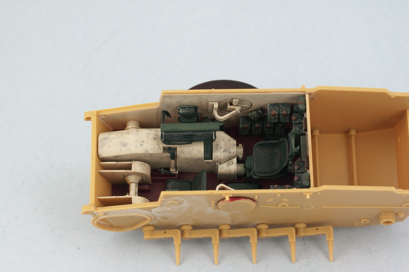
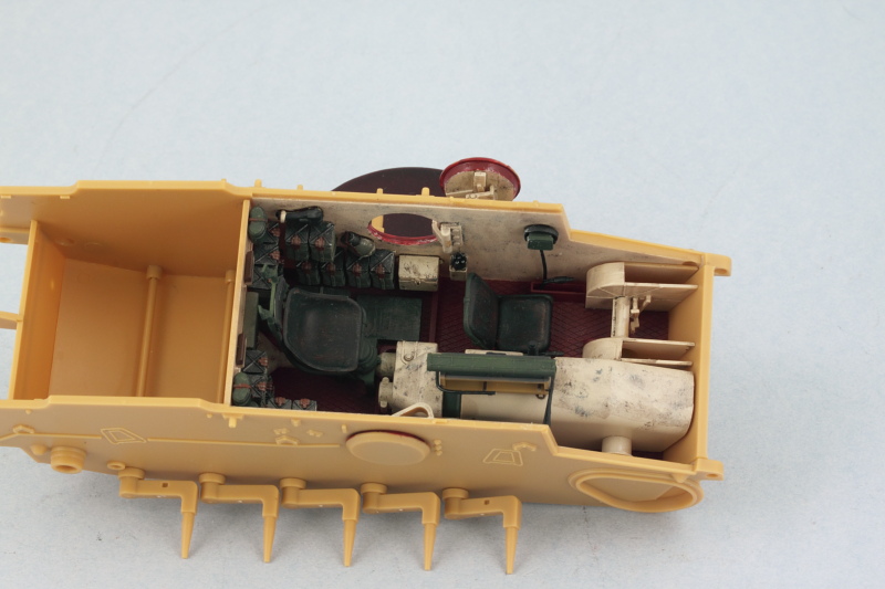
Now comes the tricky part, getting all the stuff to install just right in all the different spots! I started with the rear firewall as it's the most densely populated spot and also interacts with stuff on the floor and the hull sides. I found that working from the bottom up was the best way to go and did the right side first, checking alignment with things on the floor and the hull side as I added each row of items.
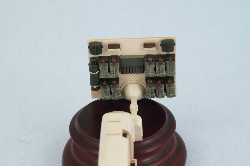
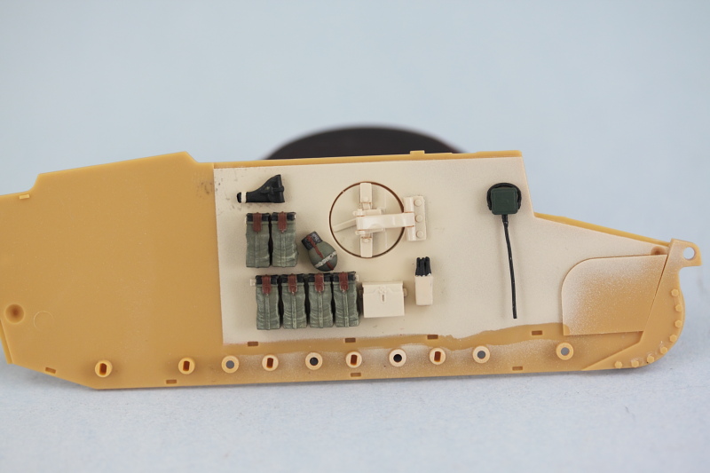
That of course meant that I also worked on the hull sides at the same time. First up was the driver's side. Ammo sacks and canteen were installed along with the hand-detailed flare gun, flare cartridges and box, and driver's intercom box and headphones. I added the wiring for the intercom using 0.5mm solder installed in the hole I'd drilled out previously with some CA gel.
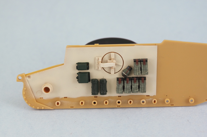
Opposite site received ammo sacks and canteen, gas mask containers, and the radio power transformer units.
With the firewall squared away, I also added the wiring details to the radios with 0.5mm solder wire and installed it in position along with the spare MG13 barrels case.
Floor received some weathering attention with a light wash of Raw Sienna applied to simulate some dirt accumulation. Virtually all of this will disappear once the drive-train is installed along with the commander's seat but enough will show through to add some color variety. I also installed the small tool box and first-aid kit along with the driver's seat and track control levers.
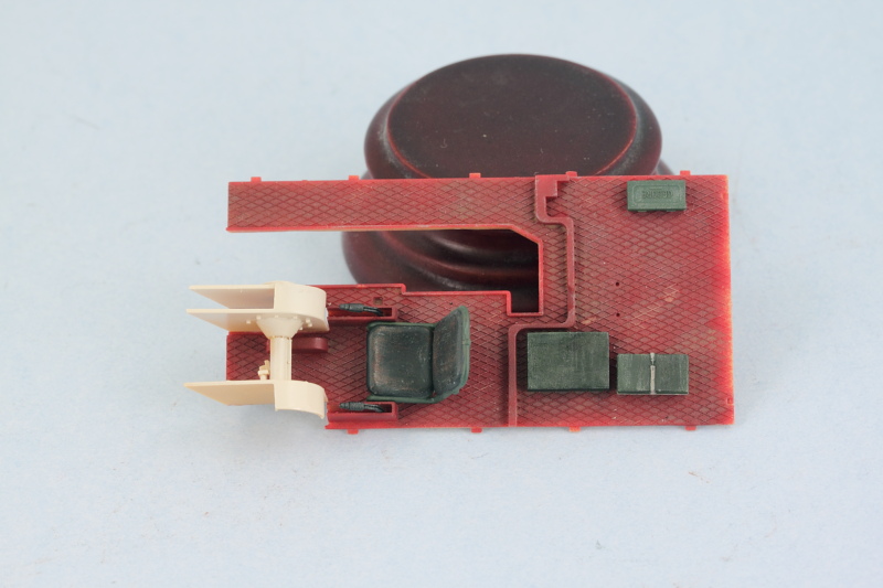
Rounding out the day's activities, the commander's seat was detailed along with the driver's instrument panel and periscope view sights.
There's still more to do weathering-wise before the interior is ready to be assembled but it's definitely closer to 'the day' than it was before!
Now comes the tricky part, getting all the stuff to install just right in all the different spots! I started with the rear firewall as it's the most densely populated spot and also interacts with stuff on the floor and the hull sides. I found that working from the bottom up was the best way to go and did the right side first, checking alignment with things on the floor and the hull side as I added each row of items.
That of course meant that I also worked on the hull sides at the same time. First up was the driver's side. Ammo sacks and canteen were installed along with the hand-detailed flare gun, flare cartridges and box, and driver's intercom box and headphones. I added the wiring for the intercom using 0.5mm solder installed in the hole I'd drilled out previously with some CA gel.
Opposite site received ammo sacks and canteen, gas mask containers, and the radio power transformer units.
With the firewall squared away, I also added the wiring details to the radios with 0.5mm solder wire and installed it in position along with the spare MG13 barrels case.
Floor received some weathering attention with a light wash of Raw Sienna applied to simulate some dirt accumulation. Virtually all of this will disappear once the drive-train is installed along with the commander's seat but enough will show through to add some color variety. I also installed the small tool box and first-aid kit along with the driver's seat and track control levers.
Rounding out the day's activities, the commander's seat was detailed along with the driver's instrument panel and periscope view sights.
There's still more to do weathering-wise before the interior is ready to be assembled but it's definitely closer to 'the day' than it was before!
-
Bill Plunk
- Posts: 1245
- Joined: Wed Sep 28, 2022 10:18 pm
WIP 05-04-2014
Happy Star Wars Day everyone, May the 4th be with you!
Ok, so now that's out of the way, work continued on the pocket Tiger by virtue of getting the interior weathering completed and the components ready for final assembly into the hull. I stippled some Burnt Umber to simulate scuffs/scrapes on the Panzer Interior Buff surfaces then applied a light wash of Raw Umber over that for general grime/dirt. Once that had dried, I dry-brushed more of the Panzer Interior Buff to blend things back in a bit and then joined the transmission housing and rear bulkhead with the floor and installed the commander's seat in position.
The hull sides got the same weathering treatment and I hand painted some of the primer red for the escape hatch opening rims as reference shots show a marked color contrast here which makes sense when you consider how the hatches closed.
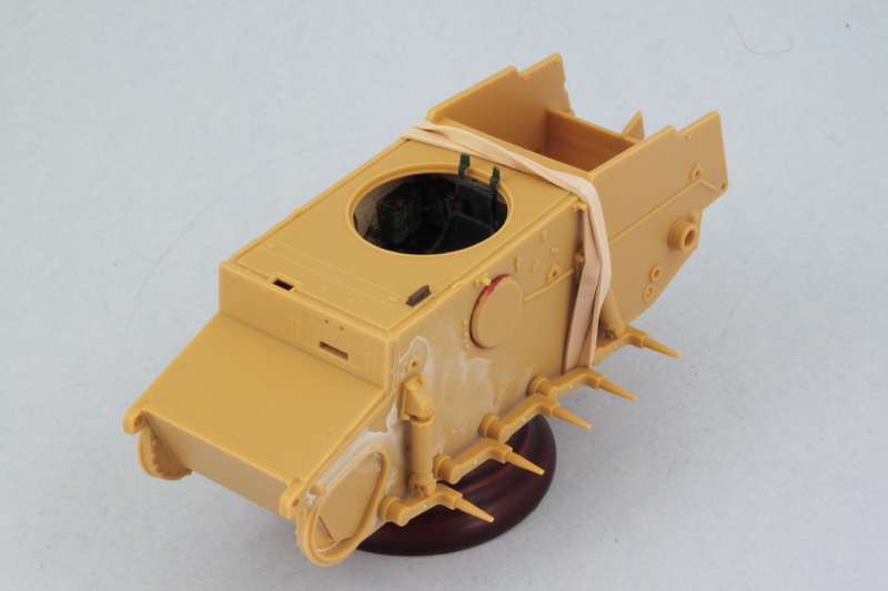
Getting all the hull components together requires some careful thought due to the way the suspension installs. Each swing arm has its own torsion bar that has to fit into a socket on the opposing hull side, so I decided to install the fighting compartment floor and interior first so that it would help hold the hull sides together, then installed the torsion bars while I could still access them from the underside.
While the hull still had some flexibility to it, I added the hull bottom and rear plates, carefully slipping their tabs into position on one side and then gently flexing the other side until they slid into place.
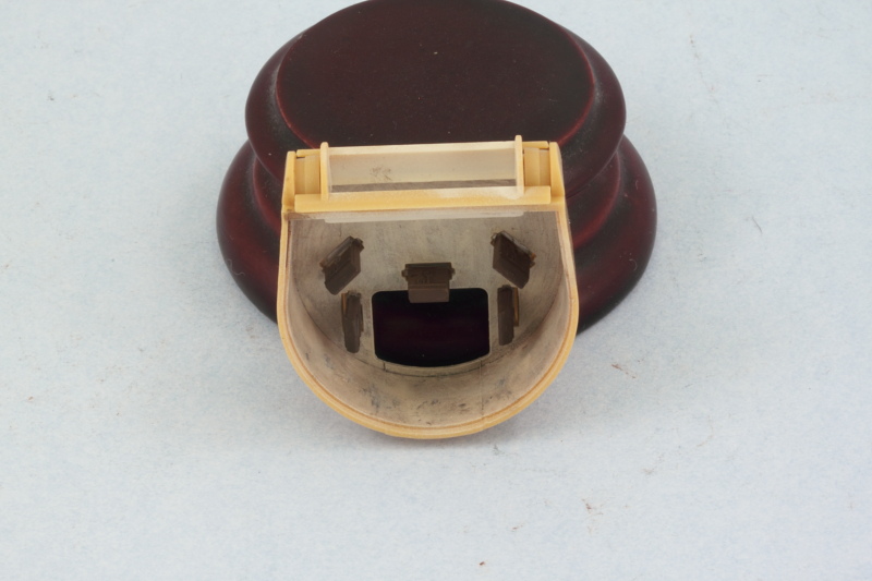
No exactly spacious accommodations by any stretch!
And just for grins, I tested out the side escape hatch and it works flawlessly.
One key element of the working suspension is to ensure that they sit at the right height. Working quickly before the glue set from the previous effort, I added the shock absorbers and used the already assembled road wheels to ensure everything was playing nice in this department. I let that set up overnight to be sure there wouldn't be problems down the road.

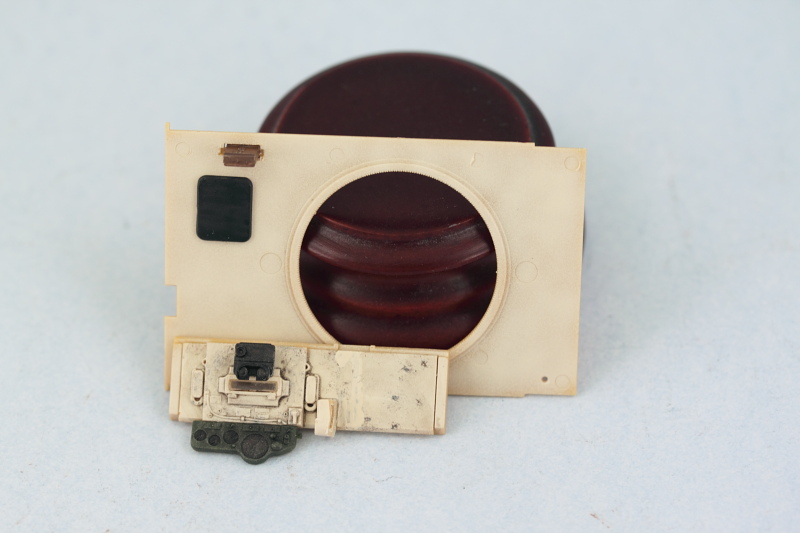
Returning back to the remaining interior bits, some test fits with the front compartment panel showed that the Bronco engineered tolerances were very tight. The added wiring on the radio that I put in interfered with the little side gauge on the driver's panel, so I had to sand it down a mm or two to adjust. The main instrument panel was also installed at this point and the compartment roof received the driver's head crash pad and side-facing periscope.
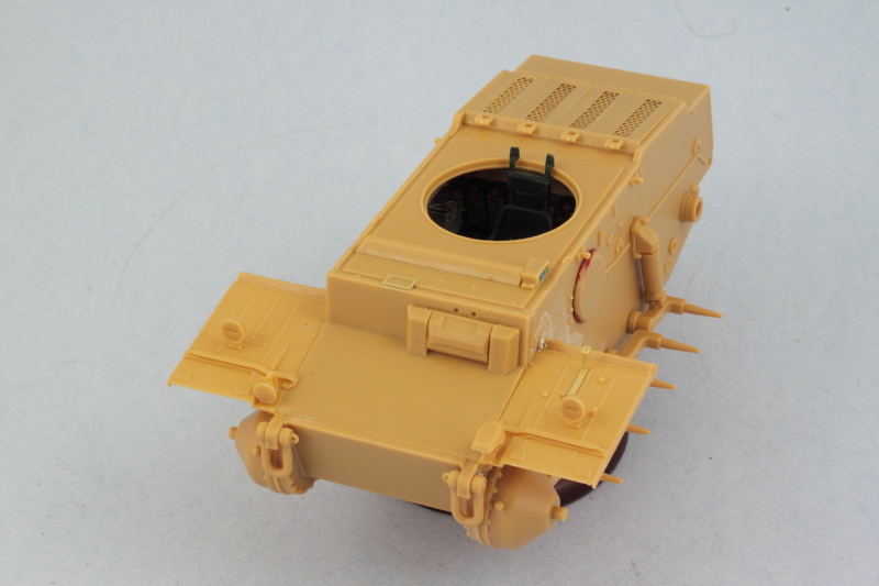
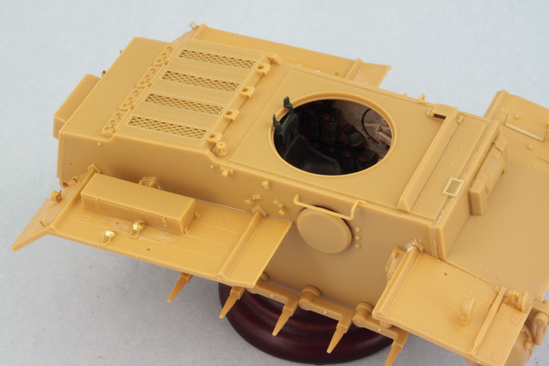
Then the moment of truth, the glacis, compartment front panel, and compartment roof were all installed. The rear part of the hull had a tendency to flex out a bit at the top so a rubber band was used to ensure that all set up nice and square.
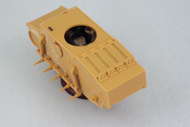
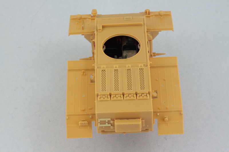
Once that had set up, I added the engine compartment access panels and rear hull top plate. I found it easiest to install the hinge plate part first so that it met up squarely with the rear hull plate and then added the 4 access hatches afterward. These all have to line up just so with each other between the hull sides with no gaps and again Bronco has this down pat with the engineering. The PE screens were installed using liquid glue around their edges to soften the kit plastic and give them something to grip onto.
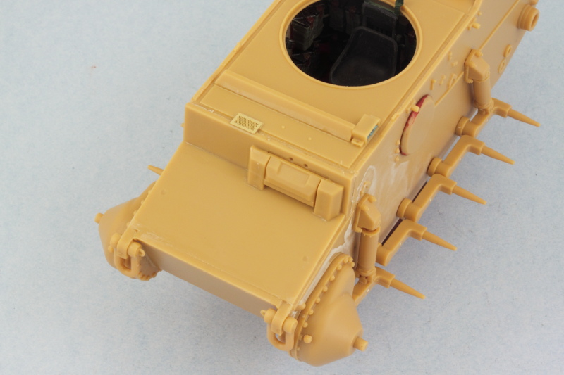
Rounding out this session, I returned to the hull front and added the tow shackles, final drive housings, and the armored visor for the driver's view port. The visor is shown here in the closed position but remains workable which will be handy for painting later on. I also added the little PE vent screen and the turret splash guard as well as the periscope guard for the driver's side periscope. The periscope itself received some blue-tack poster putty masking to protect its face later on in the painting stages.
Ok, so now that's out of the way, work continued on the pocket Tiger by virtue of getting the interior weathering completed and the components ready for final assembly into the hull. I stippled some Burnt Umber to simulate scuffs/scrapes on the Panzer Interior Buff surfaces then applied a light wash of Raw Umber over that for general grime/dirt. Once that had dried, I dry-brushed more of the Panzer Interior Buff to blend things back in a bit and then joined the transmission housing and rear bulkhead with the floor and installed the commander's seat in position.
The hull sides got the same weathering treatment and I hand painted some of the primer red for the escape hatch opening rims as reference shots show a marked color contrast here which makes sense when you consider how the hatches closed.
Getting all the hull components together requires some careful thought due to the way the suspension installs. Each swing arm has its own torsion bar that has to fit into a socket on the opposing hull side, so I decided to install the fighting compartment floor and interior first so that it would help hold the hull sides together, then installed the torsion bars while I could still access them from the underside.
While the hull still had some flexibility to it, I added the hull bottom and rear plates, carefully slipping their tabs into position on one side and then gently flexing the other side until they slid into place.
No exactly spacious accommodations by any stretch!
And just for grins, I tested out the side escape hatch and it works flawlessly.
One key element of the working suspension is to ensure that they sit at the right height. Working quickly before the glue set from the previous effort, I added the shock absorbers and used the already assembled road wheels to ensure everything was playing nice in this department. I let that set up overnight to be sure there wouldn't be problems down the road.
Returning back to the remaining interior bits, some test fits with the front compartment panel showed that the Bronco engineered tolerances were very tight. The added wiring on the radio that I put in interfered with the little side gauge on the driver's panel, so I had to sand it down a mm or two to adjust. The main instrument panel was also installed at this point and the compartment roof received the driver's head crash pad and side-facing periscope.
Then the moment of truth, the glacis, compartment front panel, and compartment roof were all installed. The rear part of the hull had a tendency to flex out a bit at the top so a rubber band was used to ensure that all set up nice and square.
Once that had set up, I added the engine compartment access panels and rear hull top plate. I found it easiest to install the hinge plate part first so that it met up squarely with the rear hull plate and then added the 4 access hatches afterward. These all have to line up just so with each other between the hull sides with no gaps and again Bronco has this down pat with the engineering. The PE screens were installed using liquid glue around their edges to soften the kit plastic and give them something to grip onto.
Rounding out this session, I returned to the hull front and added the tow shackles, final drive housings, and the armored visor for the driver's view port. The visor is shown here in the closed position but remains workable which will be handy for painting later on. I also added the little PE vent screen and the turret splash guard as well as the periscope guard for the driver's side periscope. The periscope itself received some blue-tack poster putty masking to protect its face later on in the painting stages.
-
Bill Plunk
- Posts: 1245
- Joined: Wed Sep 28, 2022 10:18 pm
WIP 05-11-2014
Made some more progress today on the exterior details although, as usual, didn't get quite as far as I would have liked but that's the way the cookie crumbles.
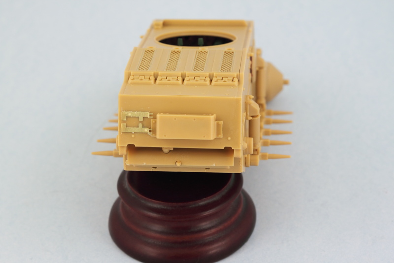
Picking up from last week, I worked on the rear hull plate as called for in Step 6. The smoke grenade box is a multi-part affair that doesn't have any locating points provided for the different parts of the box so some careful work was needed here to assemble it square and then mount it on the hull. The kit-supplied PE spare track holders were mounted in position after using a couple of the workable tracks as a guide to get them in the right spot. The pair of locator lines molded onto the plate are too far apart, so I used some Gator Grip glue to give me some work time and the ability to adjust the position to the right separation. The exhaust and heat shield were also added at this point.
Next up were the fenders, Bronco gives you a choice for the front fenders between ones with and ones without the front mud flaps. I opted for the ones without as the reference photos I've found show some with and some without them on a regular basis in the field and I thought it would give it a 'meaner' look to have them off.
In the instructions, Steps 13 through 17 deal with the fender sections and their relevant details. Bronco would have you install all the details onto the fenders first and then add them to the hull but that makes life pretty challenging especially for painting and detailing, so I made some adjustments. Starting with the front portions of the fenders, I installed the fenders themselves first to the hull and used a small bottle of paint to support the edges to keep them from sagging until the glue set. Then all the various details were added except the fire extinguisher and jack block which will come later.
While the front fenders set up, I also worked on the rear fenders. Same approach as the front, I added the fenders only to the hull and let them set up. The rear mud flaps were added and their PE stops installed along with the rear Notek light and brake light. The lights have very delicate PE mounts with tiny contact surfaces so hopefully they won't go missing between now and the finish!
Just a few small details to add to the hull sides around the crew escape hatches and then it will be time to tackle the turret and get it ready for painting.
-
Bill Plunk
- Posts: 1245
- Joined: Wed Sep 28, 2022 10:18 pm
WIP 05-18-2014
Made some solid headway on the remaining details on the pocket Tiger, although as usual I thought I would get further along than I did because this little kit is deceptive in the amount of time it takes to assemble all the little detail parts and get things just so. Part of that is the need to assemble a little bit, let the glue set, then come back and assemble some more. It means a lot of jumping around to different areas and I'm rapidly running out of those, so there was more 'wait' than 'hurry' this time around.
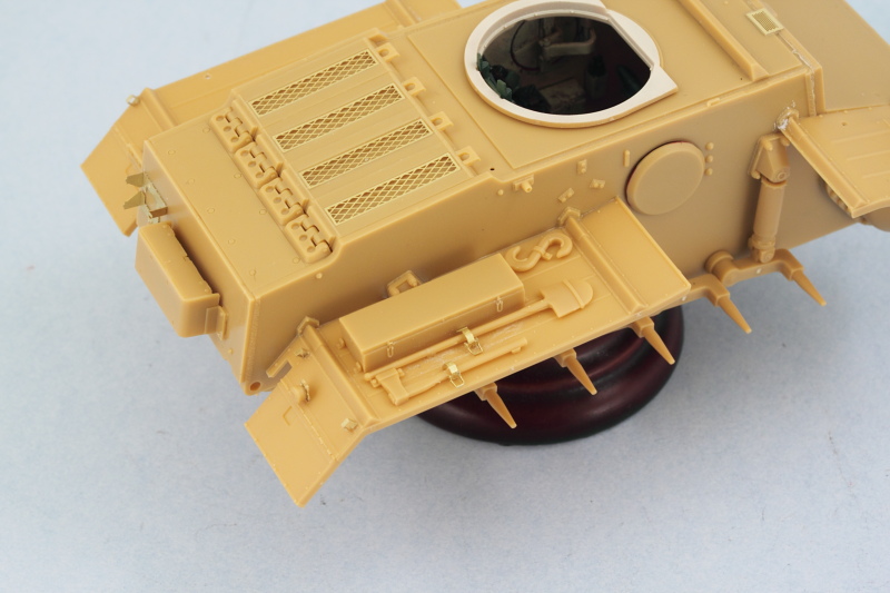
On to the fun! Progress continued on the fenders, I cleaned up all the necessary tools, assembled the boxes, and the jack. Bronco has you assemble two stowage boxes out of 6 parts each...4 sides, top, and bottom, and have to say I'm not a fan of that approach. I got the large one together pretty easily but the smaller one didn't play nice at all...and after checking references, it doesn't appear either of those boxes were commonly used in the field and only show up on the 'factory yard' photos...so I ditched them. This has the added benefit of also showing off the tools on the left side which otherwise would've been covered up by the larger box. The tools fit very tightly together on the left fender so I used the Bronco-supplied PE clamp handles and didn't replace the clamps completely as test fits showed that my Griffon clamps were larger and wouldn't work in the space available on this fender. Some putty filled the mount hole for the smaller box that I'm not using. Tools are only dry-fit for now and will be detailed separately.
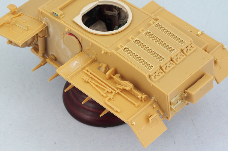
The right side fender got more attention. Bronco has the clamp for the shovel in the wrong spot according to the layout shown in Panzer Tracts 1-2, so I shaved down both it and the axe and replaced their clamps with Griffon PE clamps. The clamps are closed and the handles of both tools can be carefully slid in and out, so I can detail the tools separately off the vehicle and install permanently later.
The last little remaining details for the hull were added in the form of the PE hooks for the tow cable mounts, the side hatch grab handles, and the antenna base. The antenna base was drilled out to prep it for an RB brass antenna later on, the kit supplied item is too short for a standard German antenna. I had planned to fit tow cables since the kit doesn't provide them but the PE hooks don't appear to be sturdy enough for me to carry through on that. In hindsight, these would've been better off removed and some strip brass used to create a stronger hook but once the fenders were fitted, getting at the molded on ones to remove them is near impossible...so no cables for this baby.
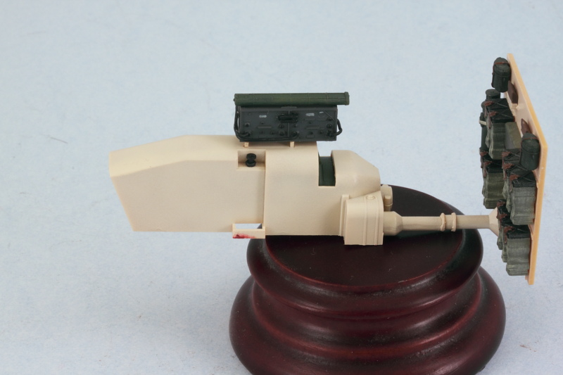
Attention also turned to the turret details, I assembled the external mantlet's MG sleeves and their little guards. The kit instructions would have you add the guards to the sleeves first and then install the sleeves to the mantlet but I did the opposite to avoid damaging them as they are a little fragile until the glue sets up. The MGs were assembled and these babies are very nicely detailed...but that also means lots of little parts for them, so these were done in stages. The instructions would have you add the ammo bags to the guns and then install the guns into the mantlet from inside the turret, but after doing some tests it's possible to install the guns into the mantlet first, then install the mantlet and guns to the turret, and then add the ammo bags from below, so that's the way I will do it.
Last but not least for the day, the turret was weathered and the commander's periscopes detailed and installed.
Next up will be finishing the details on the guns and the turret bottom and then getting the turret together so exterior painting can commence.
On to the fun! Progress continued on the fenders, I cleaned up all the necessary tools, assembled the boxes, and the jack. Bronco has you assemble two stowage boxes out of 6 parts each...4 sides, top, and bottom, and have to say I'm not a fan of that approach. I got the large one together pretty easily but the smaller one didn't play nice at all...and after checking references, it doesn't appear either of those boxes were commonly used in the field and only show up on the 'factory yard' photos...so I ditched them. This has the added benefit of also showing off the tools on the left side which otherwise would've been covered up by the larger box. The tools fit very tightly together on the left fender so I used the Bronco-supplied PE clamp handles and didn't replace the clamps completely as test fits showed that my Griffon clamps were larger and wouldn't work in the space available on this fender. Some putty filled the mount hole for the smaller box that I'm not using. Tools are only dry-fit for now and will be detailed separately.
The right side fender got more attention. Bronco has the clamp for the shovel in the wrong spot according to the layout shown in Panzer Tracts 1-2, so I shaved down both it and the axe and replaced their clamps with Griffon PE clamps. The clamps are closed and the handles of both tools can be carefully slid in and out, so I can detail the tools separately off the vehicle and install permanently later.
The last little remaining details for the hull were added in the form of the PE hooks for the tow cable mounts, the side hatch grab handles, and the antenna base. The antenna base was drilled out to prep it for an RB brass antenna later on, the kit supplied item is too short for a standard German antenna. I had planned to fit tow cables since the kit doesn't provide them but the PE hooks don't appear to be sturdy enough for me to carry through on that. In hindsight, these would've been better off removed and some strip brass used to create a stronger hook but once the fenders were fitted, getting at the molded on ones to remove them is near impossible...so no cables for this baby.
Attention also turned to the turret details, I assembled the external mantlet's MG sleeves and their little guards. The kit instructions would have you add the guards to the sleeves first and then install the sleeves to the mantlet but I did the opposite to avoid damaging them as they are a little fragile until the glue sets up. The MGs were assembled and these babies are very nicely detailed...but that also means lots of little parts for them, so these were done in stages. The instructions would have you add the ammo bags to the guns and then install the guns into the mantlet from inside the turret, but after doing some tests it's possible to install the guns into the mantlet first, then install the mantlet and guns to the turret, and then add the ammo bags from below, so that's the way I will do it.
Last but not least for the day, the turret was weathered and the commander's periscopes detailed and installed.
Next up will be finishing the details on the guns and the turret bottom and then getting the turret together so exterior painting can commence.