
Dragon Sdkfz 250/1 Neu Premium Edition (2008)
-
Bill Plunk
- Posts: 1245
- Joined: Wed Sep 28, 2022 10:18 pm
Dragon Sdkfz 250/1 Neu Premium Edition (2008)
Build log for Dragon kit #6427 Sdkfz 250/1 Neu Premium Edition.
-
Bill Plunk
- Posts: 1245
- Joined: Wed Sep 28, 2022 10:18 pm
WIP 11-25-2007
Work began where it usually does, at Step 1! This step is a very simple step, it installs the sprocket drive housings, parts H3/H6, to the hull tub.

I skipped Step 2 since that deals with the installation of the suspension arms and the idler arm. Test fits showed just a little bit of play in the arms so to avoid issues when the tracks are constructed, they will be installed later.
Step 3 deals with all of the road wheels and the sprockets. The sprockets are 3 part assemblies and each part has 4 connection points, so care is needed when removing from the sprues. The insert, G3, needs to be installed to H2 first to avoid problems and I used locking tweezers to slowly clamp each of the rollers together 2 at a time using liquid glue. The idler pair, parts G20/G4, are different from the standard road wheel pair in that G20 has a larger hole, so I marked these on the back with a Sharpie to insure I don't get them mixed up later on. The contact pins for the road wheel halves are tiny and not very helpful in keeping alignment, so I went slow through this part and made sure each wheel set was aligned properly before moving on to the next one.

Steps 4 and 5 deal with the installation of the wheels and the tracks, both of which were skipped. However the base for the steering rod, A8, was installed. Step 6 deals with the main part of the front wheel suspension and consists of 4 parts. All of these are from the older mold and need a bit more clean-up on seam lines as a result. The suspension is not workable/positionable without alteration, so I assembled parts A1, A4, and A5 together first and then glued them into the lower hull before attaching the Y-shaped brace part A6.

Step 7 adds some additional suspension details in the form of the steering linkage and the tow hooks.

This step also deals with the construction of the front tires and wheel hubs. Each tire is constructed from 5 slices plus the wheel hub and the instructions are misleading a bit here in terms of when the hub needs to be added to the "stack" of slices. It's not possible to keep the wheel hub separate for painting and still construct the wheel since the first two slices need to be attached first.

Then the rest of the slices can be added on top of that to construct a very detailed tread pattern. Once all the slices were in place, I ran some liquid glue carefully around the lip of the rim to secure the hub in place.

This was repeated for the second tire to complete the step. Later on I'll use a sharp knife point to modify the U on the "Continentau" and see about adding a piece of stretched sprue or something for the missing valve stem for the tires.

Next up will start work on the interior.
I skipped Step 2 since that deals with the installation of the suspension arms and the idler arm. Test fits showed just a little bit of play in the arms so to avoid issues when the tracks are constructed, they will be installed later.
Step 3 deals with all of the road wheels and the sprockets. The sprockets are 3 part assemblies and each part has 4 connection points, so care is needed when removing from the sprues. The insert, G3, needs to be installed to H2 first to avoid problems and I used locking tweezers to slowly clamp each of the rollers together 2 at a time using liquid glue. The idler pair, parts G20/G4, are different from the standard road wheel pair in that G20 has a larger hole, so I marked these on the back with a Sharpie to insure I don't get them mixed up later on. The contact pins for the road wheel halves are tiny and not very helpful in keeping alignment, so I went slow through this part and made sure each wheel set was aligned properly before moving on to the next one.
Steps 4 and 5 deal with the installation of the wheels and the tracks, both of which were skipped. However the base for the steering rod, A8, was installed. Step 6 deals with the main part of the front wheel suspension and consists of 4 parts. All of these are from the older mold and need a bit more clean-up on seam lines as a result. The suspension is not workable/positionable without alteration, so I assembled parts A1, A4, and A5 together first and then glued them into the lower hull before attaching the Y-shaped brace part A6.
Step 7 adds some additional suspension details in the form of the steering linkage and the tow hooks.
This step also deals with the construction of the front tires and wheel hubs. Each tire is constructed from 5 slices plus the wheel hub and the instructions are misleading a bit here in terms of when the hub needs to be added to the "stack" of slices. It's not possible to keep the wheel hub separate for painting and still construct the wheel since the first two slices need to be attached first.
Then the rest of the slices can be added on top of that to construct a very detailed tread pattern. Once all the slices were in place, I ran some liquid glue carefully around the lip of the rim to secure the hub in place.
This was repeated for the second tire to complete the step. Later on I'll use a sharp knife point to modify the U on the "Continentau" and see about adding a piece of stretched sprue or something for the missing valve stem for the tires.
Next up will start work on the interior.
-
Bill Plunk
- Posts: 1245
- Joined: Wed Sep 28, 2022 10:18 pm
WIP 12-07-2007
Made some progress on the interior, I decided that the best approach is going to be a "modular" one, meaning that I'm going to keep the interior broken down into sub-components as much as possible before painting.
Step 8 deals with the first module, the floor plate and seats for the driver and commander. The floor plate is one piece and the seats are two pieces, one for the seat itself and the other for the back rest. These installed easily enough, just a little care needed to get the tabs seated all the way into the bases with some liquid glue. This step also calls for the plate to be installed into the lower hull but I've held off doing that just yet.

Step 9 deals with the firewall for the driver's compartment. I installed all of the parts except the steering wheel, this will be painted separately and then installed. The details here are somewhat basic with the foot pedals just square representations and the gear shift lever is on the simplified side of things.

Step 10 deals with the rear compartment plate and various details. The locker for the MG ammo is a two piece assembly with the doors attached directly to the box in the closed position. The fuel filler cap is added to the rear and the long bench seat for the left side is also assembled and installed. Attached to the side of the ammo locker is the spare MG barrel holder and MG toolkit container, although looking at interior reference photos it looks as if the part has these reversed but it's not a huge thing considering. Last but not least, two holes need to be opened up in the right side of the floor to take the pedestal mount for the extra seat. Take care when doing this as the holes need to be big enough for the mount but not too big as the edge of the pedestal base isn't very wide to begin with. The seat itself is a two part assembly like the driver/commander seats and I used a bit of blue tack to dry-fit it in place to be sure it would clear the MG case behind it.

Next up will be the compartment sides, which ought to be a lot of fun as this is where much of the "premium" treatment gets applied.
Step 8 deals with the first module, the floor plate and seats for the driver and commander. The floor plate is one piece and the seats are two pieces, one for the seat itself and the other for the back rest. These installed easily enough, just a little care needed to get the tabs seated all the way into the bases with some liquid glue. This step also calls for the plate to be installed into the lower hull but I've held off doing that just yet.
Step 9 deals with the firewall for the driver's compartment. I installed all of the parts except the steering wheel, this will be painted separately and then installed. The details here are somewhat basic with the foot pedals just square representations and the gear shift lever is on the simplified side of things.
Step 10 deals with the rear compartment plate and various details. The locker for the MG ammo is a two piece assembly with the doors attached directly to the box in the closed position. The fuel filler cap is added to the rear and the long bench seat for the left side is also assembled and installed. Attached to the side of the ammo locker is the spare MG barrel holder and MG toolkit container, although looking at interior reference photos it looks as if the part has these reversed but it's not a huge thing considering. Last but not least, two holes need to be opened up in the right side of the floor to take the pedestal mount for the extra seat. Take care when doing this as the holes need to be big enough for the mount but not too big as the edge of the pedestal base isn't very wide to begin with. The seat itself is a two part assembly like the driver/commander seats and I used a bit of blue tack to dry-fit it in place to be sure it would clear the MG case behind it.
Next up will be the compartment sides, which ought to be a lot of fun as this is where much of the "premium" treatment gets applied.
-
Bill Plunk
- Posts: 1245
- Joined: Wed Sep 28, 2022 10:18 pm
WIP 12-08-2007
Continuing on with the interior today, I skipped Step 11 as that calls for the installation of all the interior sections into the lower hull. Steps 12 and 13 deal with the new interior layout for the two different sides.
As a result of this being a "Premium" edition, the hull side panels have a mix-and-match set of molded in placement lines, some of which are appropriate for this kit and others left over from the older release. Why DML went through the trouble of adding new molded in locater guides but didn't remove the old ones is somewhat of a mystery, but that's the way it is on both sides of the hull. The newer locater marks overlap the old ones in many places as a result.

I started with the left hull side first, removing all the un-needed mold lines from the old kit as well as the new ones that were added for the large PE box that goes roughly in the middle according to the instructions. This box doesn't belong to a /1 variant, it belongs to the /5 spotting variant and since it won't be installed, the mold lines also went.

The right side required more surgery since it had molded on heavy mount points for the right side stowage bin not present on the Neu as well as a curved mount point that was a holdover from the older kit.

Once that was taken care of, I started in adding the details for the left side. The "premium" treatment here deals primarily with the addition of PE mount brackets and Gen 2 crew gear. Curiously, the MP38s provided in the added WA sprue are not identical...one has the folding stock molded in place and the other has the folding stock as a separate piece...and they both have different receiver/bolt mechanisms, one that is in the charged position and the other not...and although the instructions indicate you have a choice with the double arrows, only one of each is provided so your choice is really which one goes on which side!
The brackets for the MP38s are provided as PE and the instructions aren't very helpful in how to bend them to the necessary shape as they show them already installed, however after some study I was able to figure it out. The PE brackets are not the same size as the molded on locater positions, being somewhat shorter, so testing their respective positions just forward of the trigger and just forward of the magazine is essential to get their placement correct.
Fitting the brackets to the mess tins is a real pain...the Gen 2 tins have prominent features molded on them top and bottom and their little "ear" handles off each side make it an adventure to get the straps and brackets to line up properly. The little PE buckle portions that are on these were so fragile that they broke off with the slightest bit of pressure...a shame they weren't a bit more sturdy as they were a nice added detail. Last but not least, I added the stick grenade brackets one at a time starting at the rear and working my way forward. The instructions indicate only to fill 4 of the 6 brackets since the added GC sprue only has 4 "standard" grenades, although 4 additional are provided of a type I'm not familiar with. These are the normal grenades plus some sort of projection added to the "can" at the end of the stick, these however are too long to fit the brackets, so unless you have grenades from another kit to use, 4's the limit as provided. I carefully bent the clips so that the grenades could be added later after the panel has been painted.

Next up came the right side. This one has a bit more gear than the left side. I gave the PE signal flag racks, MA10 and MA18, a try but while their one-piece design was innovative, the tiny connection points for the little trays proved to be my undoing. Since these have to be shaped in a curve, I annealed it and as I was working on shaping the curves, the entire thing literally fell apart in my hand. The PE is too springy without annealing to shape the curve, so it's a Catch-22...and mine won't have this feature in the end. I'm not 100% sure it belonged to the /1 vs. the /5 to begin with, but wanted to give it a shot to see how they would assemble.
Just as with the left side, the various crew kit items were constructed and installed. I ran into a small problem with the three-in-a-row mess tin holders...due to the dimensions of the Gen 2 mess kits, it's not possible to fit 3 of them into the space designated and still be able to fit the gas mask and fire extinguisher as well as have the necessary room for the MP38 magazine that sticks down...so my novel solution was to install the third kit bracket empty. I also ran into a slight problem with the MP38 for this side, the one with the folding stock molded on...turns out the mount brackets aren't wide enough to fit around the folded mount in position, so some careful trimming with the hobby knife was necessary here as well.

The day's adventures didn't stop there...but a little calm before the next storm. I skipped over Step 14 since that installs the side panels to the hull as well as Step 15 which deals with the side fenders. Step 16 was largely skipped as well except for the construction of the rear hull panel and installation of the crew hatch door. The interior face of the panel and the door had slight raised sink marks that needed to be dealt with but these were very faint and just a small bit of sanding was all that was required. The door was installed in the closed position.

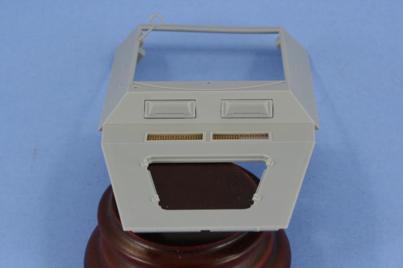
Staying with the interior prep work, next up was the upper hull. I installed the PE grills for the engine intake vents, a much improved area vs. the old vinyl mesh for sure. Other odds and ends details were also installed, except for the crew water bottles, as needed. When it came time to do the driver/radio operator visors is when the fun started. The "premium" package includes the now-familiar clear multi-part assembly for the visors, armored glass, and interior frames that allow for the visor to be posed open or closed on the 251 family of vehicles. As I went to test fit these before installation, I noticed a curious thing...the visors were too small vs. the openings in the hull plate. Since I have the older release kit in the stash, I pulled that at and compared the new clear visors to the old kit ones and sure enough, the older kit visors were larger.

Now the side-by-side difference may not seem like much, but it makes a huge difference when installing these as the frames that support them are the same dimensions...meaning that there's a noticeable gap around the perimeter if you use the supplied clear styrene parts. The "premium" kit still includes the parts on the sprue, E28/E29 and marked as not for use, that are the old kit armored glass/frames housings but the "premium" sprues DO NOT include the old visors. Fortunately, the old kit has 4 visors on the B sprues and only 2 are needed, so I snagged those for use on the "premium" kit. When the older parts are installed, they fill the cutout as they should. Just to highlight the difference, I placed the clear visor on the left over the kit backed frame to show just how much of a size difference there is. It would be possible to use sheet styrene and "fill" the cutouts to make up for this but it would produce a slightly off-center look to the visors unless you did it evenly on either side...a real pain given how small the total difference is. My only conclusion is that DML assumed that the visor dimensions would be the same on the 250 kit as on the 251s that these were originally designed for...and they aren't. You might be able to get by with installing both of the visors in the open position but I had a hard time installing the frames due to the size difference in the first place which is how I discovered the discrepancy so a gap would still likely be present to be dealt with.

To round out the upper hull details, the instrument panel and radio were installed. These have nice molded on features that ought to make it easier to hand-paint their details. No instrument face decals are provided as in the 251 kits, so that's the only option for this area, but not a hardship really, just an observation.

To add insult to injury, as I was looking over the sub-assemblies to prep them for painting tomorrow, I was checking out the leather transmission cover that doubles as a rest/stand for the MG34/42 gunner's position and discovered that there's no transmission in the kit to go under the cover. Checking the older release, it too didn't have it but was an item that was included in the 250/10 kit #6139 on it's own little two-part sprue. Since they threw in sprues from other kits, why they left out this important detail is beyond me.


As a result of this being a "Premium" edition, the hull side panels have a mix-and-match set of molded in placement lines, some of which are appropriate for this kit and others left over from the older release. Why DML went through the trouble of adding new molded in locater guides but didn't remove the old ones is somewhat of a mystery, but that's the way it is on both sides of the hull. The newer locater marks overlap the old ones in many places as a result.
I started with the left hull side first, removing all the un-needed mold lines from the old kit as well as the new ones that were added for the large PE box that goes roughly in the middle according to the instructions. This box doesn't belong to a /1 variant, it belongs to the /5 spotting variant and since it won't be installed, the mold lines also went.
The right side required more surgery since it had molded on heavy mount points for the right side stowage bin not present on the Neu as well as a curved mount point that was a holdover from the older kit.
Once that was taken care of, I started in adding the details for the left side. The "premium" treatment here deals primarily with the addition of PE mount brackets and Gen 2 crew gear. Curiously, the MP38s provided in the added WA sprue are not identical...one has the folding stock molded in place and the other has the folding stock as a separate piece...and they both have different receiver/bolt mechanisms, one that is in the charged position and the other not...and although the instructions indicate you have a choice with the double arrows, only one of each is provided so your choice is really which one goes on which side!
The brackets for the MP38s are provided as PE and the instructions aren't very helpful in how to bend them to the necessary shape as they show them already installed, however after some study I was able to figure it out. The PE brackets are not the same size as the molded on locater positions, being somewhat shorter, so testing their respective positions just forward of the trigger and just forward of the magazine is essential to get their placement correct.
Fitting the brackets to the mess tins is a real pain...the Gen 2 tins have prominent features molded on them top and bottom and their little "ear" handles off each side make it an adventure to get the straps and brackets to line up properly. The little PE buckle portions that are on these were so fragile that they broke off with the slightest bit of pressure...a shame they weren't a bit more sturdy as they were a nice added detail. Last but not least, I added the stick grenade brackets one at a time starting at the rear and working my way forward. The instructions indicate only to fill 4 of the 6 brackets since the added GC sprue only has 4 "standard" grenades, although 4 additional are provided of a type I'm not familiar with. These are the normal grenades plus some sort of projection added to the "can" at the end of the stick, these however are too long to fit the brackets, so unless you have grenades from another kit to use, 4's the limit as provided. I carefully bent the clips so that the grenades could be added later after the panel has been painted.
Next up came the right side. This one has a bit more gear than the left side. I gave the PE signal flag racks, MA10 and MA18, a try but while their one-piece design was innovative, the tiny connection points for the little trays proved to be my undoing. Since these have to be shaped in a curve, I annealed it and as I was working on shaping the curves, the entire thing literally fell apart in my hand. The PE is too springy without annealing to shape the curve, so it's a Catch-22...and mine won't have this feature in the end. I'm not 100% sure it belonged to the /1 vs. the /5 to begin with, but wanted to give it a shot to see how they would assemble.
Just as with the left side, the various crew kit items were constructed and installed. I ran into a small problem with the three-in-a-row mess tin holders...due to the dimensions of the Gen 2 mess kits, it's not possible to fit 3 of them into the space designated and still be able to fit the gas mask and fire extinguisher as well as have the necessary room for the MP38 magazine that sticks down...so my novel solution was to install the third kit bracket empty. I also ran into a slight problem with the MP38 for this side, the one with the folding stock molded on...turns out the mount brackets aren't wide enough to fit around the folded mount in position, so some careful trimming with the hobby knife was necessary here as well.
The day's adventures didn't stop there...but a little calm before the next storm. I skipped over Step 14 since that installs the side panels to the hull as well as Step 15 which deals with the side fenders. Step 16 was largely skipped as well except for the construction of the rear hull panel and installation of the crew hatch door. The interior face of the panel and the door had slight raised sink marks that needed to be dealt with but these were very faint and just a small bit of sanding was all that was required. The door was installed in the closed position.
Staying with the interior prep work, next up was the upper hull. I installed the PE grills for the engine intake vents, a much improved area vs. the old vinyl mesh for sure. Other odds and ends details were also installed, except for the crew water bottles, as needed. When it came time to do the driver/radio operator visors is when the fun started. The "premium" package includes the now-familiar clear multi-part assembly for the visors, armored glass, and interior frames that allow for the visor to be posed open or closed on the 251 family of vehicles. As I went to test fit these before installation, I noticed a curious thing...the visors were too small vs. the openings in the hull plate. Since I have the older release kit in the stash, I pulled that at and compared the new clear visors to the old kit ones and sure enough, the older kit visors were larger.
Now the side-by-side difference may not seem like much, but it makes a huge difference when installing these as the frames that support them are the same dimensions...meaning that there's a noticeable gap around the perimeter if you use the supplied clear styrene parts. The "premium" kit still includes the parts on the sprue, E28/E29 and marked as not for use, that are the old kit armored glass/frames housings but the "premium" sprues DO NOT include the old visors. Fortunately, the old kit has 4 visors on the B sprues and only 2 are needed, so I snagged those for use on the "premium" kit. When the older parts are installed, they fill the cutout as they should. Just to highlight the difference, I placed the clear visor on the left over the kit backed frame to show just how much of a size difference there is. It would be possible to use sheet styrene and "fill" the cutouts to make up for this but it would produce a slightly off-center look to the visors unless you did it evenly on either side...a real pain given how small the total difference is. My only conclusion is that DML assumed that the visor dimensions would be the same on the 250 kit as on the 251s that these were originally designed for...and they aren't. You might be able to get by with installing both of the visors in the open position but I had a hard time installing the frames due to the size difference in the first place which is how I discovered the discrepancy so a gap would still likely be present to be dealt with.
To round out the upper hull details, the instrument panel and radio were installed. These have nice molded on features that ought to make it easier to hand-paint their details. No instrument face decals are provided as in the 251 kits, so that's the only option for this area, but not a hardship really, just an observation.
To add insult to injury, as I was looking over the sub-assemblies to prep them for painting tomorrow, I was checking out the leather transmission cover that doubles as a rest/stand for the MG34/42 gunner's position and discovered that there's no transmission in the kit to go under the cover. Checking the older release, it too didn't have it but was an item that was included in the 250/10 kit #6139 on it's own little two-part sprue. Since they threw in sprues from other kits, why they left out this important detail is beyond me.
-
Bill Plunk
- Posts: 1245
- Joined: Wed Sep 28, 2022 10:18 pm
WIP 12-08-2007 Part 2 Addendum
Following on with the discovery yesterday that the kit doesn't have a transmission and after getting a great idea from a fellow modeler to use the often supplied tranny from a 251 kit, I dug around in the spares box and assembled one from the parts on Sprue C common to all DML 251 kits. They aren't quite the same as the 250 parts that were provided in the 250/10, but it's close enough to fit the bill. The nose pin on the 251 tranny fits perfectly into the housing under the dashboard but will not sit flat on the floor and will "float" a bit. This isn't a big issue necessarily but it does mean that you need a very good join at the nose to avoid it drooping.
The cover/cushion, C19, needs to be modified by having its pin removed, and then can be glued in place carefully over the new transmission. The cover only makes contact at the rear and along the left side, so careful gluing and positioning is key for it to sit properly.

Test fit into the compartment shows that this work-around will do...the cushion still sits just a touch lower than it should, but once the sides and top are in place, it won't be noticeable and is far better than if not used at all. I'll let this dry up good and solid before painting to be sure it doesn't shift around.

The cover/cushion, C19, needs to be modified by having its pin removed, and then can be glued in place carefully over the new transmission. The cover only makes contact at the rear and along the left side, so careful gluing and positioning is key for it to sit properly.
Test fit into the compartment shows that this work-around will do...the cushion still sits just a touch lower than it should, but once the sides and top are in place, it won't be noticeable and is far better than if not used at all. I'll let this dry up good and solid before painting to be sure it doesn't shift around.
-
Bill Plunk
- Posts: 1245
- Joined: Wed Sep 28, 2022 10:18 pm
WIP 12-31-2007
After a long break due to many different reasons, including the holidays and vacations, I was able to pick this one back up again today.
The first thing that needed to be done was to paint the interior, so I masked off the important mating surfaces with masking tape and applied a coat of straight Model Master Dunkelgelb enamel to all of the interior sub-assemblies. I deliberately didn't lighten it as I would for the exterior in order to provide a color differentiation interior vs. exterior.

With that out of the way, the different areas got their various detailing attention, starting with the driver's instrument panel and radio. The kit doesn't include any decals for the instrument faces but the detail is molded well enough that it's possible with creative dry-brushing to bring their details out. Since I couldn't use the kit-supplied clear styrene parts, I simulated the glass by painting it with Silver and then giving it an overcoat of Tamiya Clear Smoke.

Next up were the hull sides with their various crew kit items. The side panels were also given an overall wash of thinned down Burnt Umber to provide some wear and color contrast.


Then I worked on the floor sub-sections. All of the leather seats were first painted with Leather and then given a wash of thinned enamel Gunmetal. The anti-skid floor plates received the same Gunmetal wash followed by a Burnt Umber wash and then dry-brushed with lightened Dunkelgelb.


Last but not least, the rear plate and hatch received a Burnt Umber wash and dry-brushed with lightened Dunkelgelb to prepare it for inclusion in the interior.

With that out of the way, I secured the floor sub-sections in place and then attached both of the side panels, making sure to get a solid even join front-to-back using liquid glue, particularly around the instrument panel bulkhead area.

Then the nose plate and rear plate were installed as directed in Step 16, with careful dry-fit checks with the upper hull to insure the alignment was correct at both ends.

I also managed to get the left side fender and storage boxes mounted but will finish the right side tomorrow. The storage boxes have the options for both boxes to be either open or closed, a welcome change from the 251 series approach as it allows for a consistent look between the different boxes if you elect to close them both up IMHO. Extra care is needed when attaching part E12 to the front fender, E10, since this has to align perfectly with E6 for the whole thing to match up. I also left off the top half of the exhaust/muffler pot after a test fit showed it's possible to slide this in carefully later and will make it easier to paint/detail it off the kit.

Happy New Year everyone!
The first thing that needed to be done was to paint the interior, so I masked off the important mating surfaces with masking tape and applied a coat of straight Model Master Dunkelgelb enamel to all of the interior sub-assemblies. I deliberately didn't lighten it as I would for the exterior in order to provide a color differentiation interior vs. exterior.
With that out of the way, the different areas got their various detailing attention, starting with the driver's instrument panel and radio. The kit doesn't include any decals for the instrument faces but the detail is molded well enough that it's possible with creative dry-brushing to bring their details out. Since I couldn't use the kit-supplied clear styrene parts, I simulated the glass by painting it with Silver and then giving it an overcoat of Tamiya Clear Smoke.
Next up were the hull sides with their various crew kit items. The side panels were also given an overall wash of thinned down Burnt Umber to provide some wear and color contrast.
Then I worked on the floor sub-sections. All of the leather seats were first painted with Leather and then given a wash of thinned enamel Gunmetal. The anti-skid floor plates received the same Gunmetal wash followed by a Burnt Umber wash and then dry-brushed with lightened Dunkelgelb.
Last but not least, the rear plate and hatch received a Burnt Umber wash and dry-brushed with lightened Dunkelgelb to prepare it for inclusion in the interior.
With that out of the way, I secured the floor sub-sections in place and then attached both of the side panels, making sure to get a solid even join front-to-back using liquid glue, particularly around the instrument panel bulkhead area.
Then the nose plate and rear plate were installed as directed in Step 16, with careful dry-fit checks with the upper hull to insure the alignment was correct at both ends.
I also managed to get the left side fender and storage boxes mounted but will finish the right side tomorrow. The storage boxes have the options for both boxes to be either open or closed, a welcome change from the 251 series approach as it allows for a consistent look between the different boxes if you elect to close them both up IMHO. Extra care is needed when attaching part E12 to the front fender, E10, since this has to align perfectly with E6 for the whole thing to match up. I also left off the top half of the exhaust/muffler pot after a test fit showed it's possible to slide this in carefully later and will make it easier to paint/detail it off the kit.
Happy New Year everyone!
-
Bill Plunk
- Posts: 1245
- Joined: Wed Sep 28, 2022 10:18 pm
Corrections to 12-31-2007 WIP
Two small corrections to what I posted yesterday. The first is the instrument panel, the smaller gauges should have black faces, not white, so these were fixed.

The second deals with the position of the hand grenades on the right hull side. I had these in upside down (fortunately not glued in place, only held by the clips), so they've been reversed and glued in place with a dot of CA gel.

The second deals with the position of the hand grenades on the right hull side. I had these in upside down (fortunately not glued in place, only held by the clips), so they've been reversed and glued in place with a dot of CA gel.
-
Bill Plunk
- Posts: 1245
- Joined: Wed Sep 28, 2022 10:18 pm
WIP 01-01-2008
Progress continued today with the remaining items from Steps 15/16 dealing with the external fenders, storage boxes, and other details. One of the "premium" upgrades to this kit is the inclusion of brass width indicator rods to replace the kit parts, a feature common to the 251 series of kits. The rods are provided as straight items that need to be bent to shape and, unlike the 251 kits, a jig isn't provided on the sprues so I used the original part A23 as a guide and bent to shape with a pair of needle nose pliers.

As you can also see in the above pic, the diameter of the bases is different with the brass items being slightly smaller. This translates over to the size of the locater holes in the fenders themselves and to remedy this I used some Aves Apoxysculpt putty and applied it to the underside of the fenders to provide a surface that would help hold them in place. It doesn't take much putty, just enough for it provide something to catch the base against, and a small dot of CA gel on the base did the job just fine.

The last remaining item in this step was the attachment of the right side stowage boxes, this went off without a hitch and both boxes were closed up.

Steps 17-19 had already been completed earlier and Step 20 dealt with details for the upper hull, so I skipped that briefly and went straight to Step 22 to attach the upper hull to the lower. Since the contact surfaces are narrow at the front and rear, it's important to get everything lined up solid and glued down as the hull top has a slight tendency to bow in the middle if not careful. I used liquid glue and finger pressure to glue the rear areas first to get that as a solid starting point and then used rubber-bands and liquid glue along the rest of the surfaces to get everything secured.

Once the bands came off, the details from Step 20 were added in the form of the engine bay hatches, rear AA MG mount, and radio antenna mount. The rear AA MG mount hole in the hull top isn't drilled all the way through, so I trimmed off the portion of the base that would've allowed the mount to be moveable and glued it into place. If you prefer it to be moveable, the hole just needs to be carefully drilled all the way through with a pin vise.
Step 21, which deals with the engine assembly, was skipped to allow me to save the engine for future use since I didn't want to open the hatches up on this one. The instructions do call for it to be installed first before the upper hull is secured and curiously enough the diagrams show the hatches in the closed position when you do this, a hold over from the previous kit when no engine was provided no doubt. I also assembled and installed the MG42 mount and splinter shield, but first sanded down the beveled surfaces to be an even thickness on the shield using sanding twigs. The MG42 itself will be installed later. The rear Notek light was also installed and the small triangular braces under each "step" in the fenders were installed. The instructions contain an error here, the parts E20(E21) and E22(E23) should actually be reversed in terms of which side they go on. Last but not least, the driver's mirror A24 was attached to the width indicator.

Next up will be to prep everything for painting!
As you can also see in the above pic, the diameter of the bases is different with the brass items being slightly smaller. This translates over to the size of the locater holes in the fenders themselves and to remedy this I used some Aves Apoxysculpt putty and applied it to the underside of the fenders to provide a surface that would help hold them in place. It doesn't take much putty, just enough for it provide something to catch the base against, and a small dot of CA gel on the base did the job just fine.
The last remaining item in this step was the attachment of the right side stowage boxes, this went off without a hitch and both boxes were closed up.
Steps 17-19 had already been completed earlier and Step 20 dealt with details for the upper hull, so I skipped that briefly and went straight to Step 22 to attach the upper hull to the lower. Since the contact surfaces are narrow at the front and rear, it's important to get everything lined up solid and glued down as the hull top has a slight tendency to bow in the middle if not careful. I used liquid glue and finger pressure to glue the rear areas first to get that as a solid starting point and then used rubber-bands and liquid glue along the rest of the surfaces to get everything secured.
Once the bands came off, the details from Step 20 were added in the form of the engine bay hatches, rear AA MG mount, and radio antenna mount. The rear AA MG mount hole in the hull top isn't drilled all the way through, so I trimmed off the portion of the base that would've allowed the mount to be moveable and glued it into place. If you prefer it to be moveable, the hole just needs to be carefully drilled all the way through with a pin vise.
Step 21, which deals with the engine assembly, was skipped to allow me to save the engine for future use since I didn't want to open the hatches up on this one. The instructions do call for it to be installed first before the upper hull is secured and curiously enough the diagrams show the hatches in the closed position when you do this, a hold over from the previous kit when no engine was provided no doubt. I also assembled and installed the MG42 mount and splinter shield, but first sanded down the beveled surfaces to be an even thickness on the shield using sanding twigs. The MG42 itself will be installed later. The rear Notek light was also installed and the small triangular braces under each "step" in the fenders were installed. The instructions contain an error here, the parts E20(E21) and E22(E23) should actually be reversed in terms of which side they go on. Last but not least, the driver's mirror A24 was attached to the width indicator.
Next up will be to prep everything for painting!
-
Bill Plunk
- Posts: 1245
- Joined: Wed Sep 28, 2022 10:18 pm
WIP 01-05-2008
Today was a great day for painting outside and I took full advantage of it. The interior was masked off with strips of masking tape to protect its details and a pre-shade/primer coat of Italian Dark Brown laid down as the first step.

This was followed by multiple thin passes of an 80/20 Dunkelgelb/Light Gray mix for the base coat.

Then the camo pattern was applied. I decided to go with something similar to the markings/pattern that's on the box art for the 3/Pz.Aufkl.Btl. 2.Pz.Div, France 1944 and laid down the red-brown pattern first (50-50 mix of Leather and Military Brown) and then the green (80-20 Russian Armor Green and Panzerschwarzgrau). I came back with the Dunkelgelb and cleaned up the over-spray and fine-tuned the pattern in different places. Once satisfied with that, I applied a heavily thinned mist coat from about 12" away of the Dunkelgelb to the overall vehicle to provide a touch of fading and tie everything in together as a foundation for later weathering.

I also worked on the road wheels and since this is something that comes up from time to time, decided to add a couple of photos on the process I use. It's pretty simple, I mount all of the wheels on toothpicks using a small ball of blue-tack poster putty and then spray the rubber portions Flat Black. Some of the black gets on the rim portions but that's not a problem and actually helps provide some pre-shading/color variation as well.

Once the tire portions are painted, then I use a plastic circle-template, the type found at most hobby stores like Michael's or HobbyLobby or in the hardware sections, it's basically just a sheet with different diameter of circles cut out and you choose the one you need and mask it off. In this case, I needed to use three different circles, one for the main wheels, one for the outer diameter of the half-track road wheels, and one for the inner diameter of the road wheels.

I mount the wheels on toothpicks for two reasons: 1) it allows them to be stuck into a Styrofoam block for drying and 2) provides an extra "handle" and reduces risks of handling the freshly painted surfaces. The wheels are fitted to the individual circle template, the paint sprayed, and then stuck into the block to dry. Once the outer rims are dry, the same thing is then done for the inner rims.

Next up now that everything's painted will be building the tracks, mounting the suspension arms, and installing all the running gear.
This was followed by multiple thin passes of an 80/20 Dunkelgelb/Light Gray mix for the base coat.
Then the camo pattern was applied. I decided to go with something similar to the markings/pattern that's on the box art for the 3/Pz.Aufkl.Btl. 2.Pz.Div, France 1944 and laid down the red-brown pattern first (50-50 mix of Leather and Military Brown) and then the green (80-20 Russian Armor Green and Panzerschwarzgrau). I came back with the Dunkelgelb and cleaned up the over-spray and fine-tuned the pattern in different places. Once satisfied with that, I applied a heavily thinned mist coat from about 12" away of the Dunkelgelb to the overall vehicle to provide a touch of fading and tie everything in together as a foundation for later weathering.
I also worked on the road wheels and since this is something that comes up from time to time, decided to add a couple of photos on the process I use. It's pretty simple, I mount all of the wheels on toothpicks using a small ball of blue-tack poster putty and then spray the rubber portions Flat Black. Some of the black gets on the rim portions but that's not a problem and actually helps provide some pre-shading/color variation as well.
Once the tire portions are painted, then I use a plastic circle-template, the type found at most hobby stores like Michael's or HobbyLobby or in the hardware sections, it's basically just a sheet with different diameter of circles cut out and you choose the one you need and mask it off. In this case, I needed to use three different circles, one for the main wheels, one for the outer diameter of the half-track road wheels, and one for the inner diameter of the road wheels.
I mount the wheels on toothpicks for two reasons: 1) it allows them to be stuck into a Styrofoam block for drying and 2) provides an extra "handle" and reduces risks of handling the freshly painted surfaces. The wheels are fitted to the individual circle template, the paint sprayed, and then stuck into the block to dry. Once the outer rims are dry, the same thing is then done for the inner rims.
Next up now that everything's painted will be building the tracks, mounting the suspension arms, and installing all the running gear.
-
Bill Plunk
- Posts: 1245
- Joined: Wed Sep 28, 2022 10:18 pm
WIP 01-06-2008
While watching the playoff games for the NFL yesterday evening and today, I managed to complete the tracks for both sides. My method for these cap-block style of tracks is pretty simple, just hook two links together where one is hinged all the way down in an L-shape, then carefully apply a spot of glue and attach the pad. The instructions call for 38 links per side, so 19 sets is all you need. Once the pairs are constructed, then I join them into groups of 4...then 8, then link the runs together to get the 38. Each link needed to have the raised ejector marks trimmed off on either side of the guide horn but that's normal for DML "Magic" links.
Once the tracks were constructed, I installed the suspension arms that had been skipped way back in Step 1 and made sure they were all aligned and then installed the road wheels and idler, leaving the sprockets and main wheels dry-fit. There's a little pit of play in the suspension arms and doing things this way allowed me to insure that the vehicle would sit right with all the wheels contacting the ground when the tracks were installed vs. just sitting on the road wheels alone. The tracks were slid under each side and minor adjustments made where needed. The idlers were left positionable by not gluing them to the hull...the kit design allows for the idler to move somewhat back or forward for track tensioning, so while the idler was glued to its mount arm, the mount itself wasn't glued down just yet.

Once the wheels were all set up, I painted the tracks using Non-buffing Metalizer Gunmetal as the base, dry-brushed with Steel, then applied a thin Raw Umber wash to blend it all together. The rubber track pads were painted with enamel Gunmetal. I dry-brushed some Burnt Umber around the hull sides and the front fenders for some wear and then installed the tracks, sprockets, and front wheels.
I also detailed and added the pioneer tools to either side along with the muffler/exhaust and MG42. The driver's mirror was painted with some Silver and the tips of the width indicators given a touch of Light Gray to finish things off for the day.


Next up will be a coat of Future and the decals then on to the weathering.
Once the tracks were constructed, I installed the suspension arms that had been skipped way back in Step 1 and made sure they were all aligned and then installed the road wheels and idler, leaving the sprockets and main wheels dry-fit. There's a little pit of play in the suspension arms and doing things this way allowed me to insure that the vehicle would sit right with all the wheels contacting the ground when the tracks were installed vs. just sitting on the road wheels alone. The tracks were slid under each side and minor adjustments made where needed. The idlers were left positionable by not gluing them to the hull...the kit design allows for the idler to move somewhat back or forward for track tensioning, so while the idler was glued to its mount arm, the mount itself wasn't glued down just yet.
Once the wheels were all set up, I painted the tracks using Non-buffing Metalizer Gunmetal as the base, dry-brushed with Steel, then applied a thin Raw Umber wash to blend it all together. The rubber track pads were painted with enamel Gunmetal. I dry-brushed some Burnt Umber around the hull sides and the front fenders for some wear and then installed the tracks, sprockets, and front wheels.
I also detailed and added the pioneer tools to either side along with the muffler/exhaust and MG42. The driver's mirror was painted with some Silver and the tips of the width indicators given a touch of Light Gray to finish things off for the day.
Next up will be a coat of Future and the decals then on to the weathering.