
Tamiya Marder III Ausf. M 7.5cm Pak 40 auf Gw.38t Sdkfz 138 (2007)
-
Bill Plunk
- Posts: 1245
- Joined: Wed Sep 28, 2022 10:18 pm
Tamiya Marder III Ausf. M 7.5cm Pak 40 auf Gw.38t Sdkfz 138 (2007)
Build log for Tamiya's kit #35255 Marder III M with Eduard PE fenders and detail sets, Model Kasten replacement tracks, Blast Models interior resin set, and Tamiya brass ammunition rounds.
-
Bill Plunk
- Posts: 1245
- Joined: Wed Sep 28, 2022 10:18 pm
WIP 06-17-2007
A very productive Sunday today, I started in on this one wit a vengeance. The first step in the instructions calls for the assembly of the hull tub, an interesting surprise to be sure, but one that allowed for some nice detail on the hull sides. The hull side panels test fit well, but just to be sure I got a good alignment I went ahead and also prepared the fighting compartment bulkhead and floor for installation at the same time to insure a square alignment. I snapped a quick pic before installing them to show the results of the step. The holes on the front hull panel for the spare track holder were filled in with putty since I will be using the Eduard items for this instead of the kit parts.

Step 2 is a two parter, first part is the installation of the fighting compartment elements mentioned previously. The second is the installation of the upper hull and rear hull panel. Some ejector pin marks needed to be sanded and filled while others were just removed with a sharp knife depending. The fit of the top hull to the bottom was very good with only a small gap on the right side near the driver's hood that was easily filled with a little putty. I also took advantage of this opportunity to remove the solid molded on engine hatch handles and replaced them with the Eduard items. These consist of PE frames with 0.5mm diameter styrene rods for the handles and the Eduard instructions have an error...they say the rods should be 3.5mm when really they should be 2.5mm. I put a length of rod down on some masking tape and used a ruler to cut 4 sections and then glued them to the PE frames with CA. The handles were glued to the hatches after the old molded on parts were removed with liquid glue and some gentle pressure. Last but not least, the towing pintle brackets were added to both sides of the front hull.

Step 3 deals with the installation of the suspension. The suspension is non-workable and the leaf springs had some prominent seams that needed to be carefully removed to get them in good order, but nothing major. The return rollers were left off for now to make it easier to paint them later on.

Step 4 dealt with the road wheels, sprockets, and idlers. Since I'm using an MK set for the tracks, a spacer insert needed to be installed on both the sprockets and idlers to give them the right width to take the links.

The inclusion of the spacer means that the sprocket and idler halves no longer nest firmly with each other, so I had to be careful to keep them properly lined up with each other until the glue set. I also neglected to install the poly caps for the sprockets the first time around and had to pop them open again to put them in and reglue...fortunately I caught it in time! All of the road wheels had their mold seams removed with a sanding twig and along with the return rollers were set off to the side for now.

Step 5 calls for the installation of the rubber band tracks and this was skipped. Step 6 began adding details to the upper hull in the form of the driver's hood front plate and hatch, the poly cap and retainer for the gun mount, and the base shield for the gun mount. These all installed without incident. In addition, this step also began the detail work on the interior of the fighting compartment and the first elements of the Blast set were put to use. Kit parts G58 and G35 were replaced with the Blast parts and the MP40 mount removed with a sharp knife and sanded down to allow for the Blast replacement and ammo pouches. Not shown in the photo but installed afterward were an extra box for the floor that the kit didn't include and the installation of the gunner's seat on the right side.

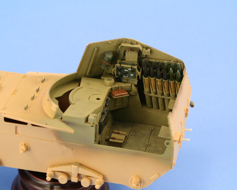
Step 7 deals with the construction of the ammunition racks and while the Blast items contain some lovely detail, including canvas tarp covers molded to them, they were damaged in transit to the point of being unusable and the kit parts updated with the Eduard bits instead. The racks have 27 holders and the Tamiya brass ammo sets each have 14 rounds (7 HE, 7 AP) to go in them, so 2 sets is just enough to do the job. I added the Eduard retaining brackets to the mouth of each ammo tube, a slow and tedious process, but produces some nice detail IMHO. The smallest rack of 3 tubes turned out to be unable to accept the brass rounds since it's not wide enough to take either the brass supplemental or the kit supplied spare rounds, so their retaining brackets were closed and those tubes will stand empty to add some variety to the interior.

I left the rack halves dry fit for now while I decide on the best way to paint them and still be able to install the ammo rounds. So far so good!
Step 2 is a two parter, first part is the installation of the fighting compartment elements mentioned previously. The second is the installation of the upper hull and rear hull panel. Some ejector pin marks needed to be sanded and filled while others were just removed with a sharp knife depending. The fit of the top hull to the bottom was very good with only a small gap on the right side near the driver's hood that was easily filled with a little putty. I also took advantage of this opportunity to remove the solid molded on engine hatch handles and replaced them with the Eduard items. These consist of PE frames with 0.5mm diameter styrene rods for the handles and the Eduard instructions have an error...they say the rods should be 3.5mm when really they should be 2.5mm. I put a length of rod down on some masking tape and used a ruler to cut 4 sections and then glued them to the PE frames with CA. The handles were glued to the hatches after the old molded on parts were removed with liquid glue and some gentle pressure. Last but not least, the towing pintle brackets were added to both sides of the front hull.
Step 3 deals with the installation of the suspension. The suspension is non-workable and the leaf springs had some prominent seams that needed to be carefully removed to get them in good order, but nothing major. The return rollers were left off for now to make it easier to paint them later on.
Step 4 dealt with the road wheels, sprockets, and idlers. Since I'm using an MK set for the tracks, a spacer insert needed to be installed on both the sprockets and idlers to give them the right width to take the links.
The inclusion of the spacer means that the sprocket and idler halves no longer nest firmly with each other, so I had to be careful to keep them properly lined up with each other until the glue set. I also neglected to install the poly caps for the sprockets the first time around and had to pop them open again to put them in and reglue...fortunately I caught it in time! All of the road wheels had their mold seams removed with a sanding twig and along with the return rollers were set off to the side for now.
Step 5 calls for the installation of the rubber band tracks and this was skipped. Step 6 began adding details to the upper hull in the form of the driver's hood front plate and hatch, the poly cap and retainer for the gun mount, and the base shield for the gun mount. These all installed without incident. In addition, this step also began the detail work on the interior of the fighting compartment and the first elements of the Blast set were put to use. Kit parts G58 and G35 were replaced with the Blast parts and the MP40 mount removed with a sharp knife and sanded down to allow for the Blast replacement and ammo pouches. Not shown in the photo but installed afterward were an extra box for the floor that the kit didn't include and the installation of the gunner's seat on the right side.
Step 7 deals with the construction of the ammunition racks and while the Blast items contain some lovely detail, including canvas tarp covers molded to them, they were damaged in transit to the point of being unusable and the kit parts updated with the Eduard bits instead. The racks have 27 holders and the Tamiya brass ammo sets each have 14 rounds (7 HE, 7 AP) to go in them, so 2 sets is just enough to do the job. I added the Eduard retaining brackets to the mouth of each ammo tube, a slow and tedious process, but produces some nice detail IMHO. The smallest rack of 3 tubes turned out to be unable to accept the brass rounds since it's not wide enough to take either the brass supplemental or the kit supplied spare rounds, so their retaining brackets were closed and those tubes will stand empty to add some variety to the interior.
I left the rack halves dry fit for now while I decide on the best way to paint them and still be able to install the ammo rounds. So far so good!
-
Bill Plunk
- Posts: 1245
- Joined: Wed Sep 28, 2022 10:18 pm
WIP 06-24-2007
Managed to get some time in on this one today, yesterday and Friday were taken up with other duties, so didn't get any bench time until this afternoon.
Picking up where I left off previously with the interior, I worked on Step 8 which deals with the installation of the various details on the sides of the fighting compartment. Since I'm doing a mix/match of the Blast items with the kit parts, some careful fitting and testing was necessary to get everything in the right place.
The interior surfaces of the compartment walls have several ejector marks that needed to be sanded down and I also removed the molded on solid canvas cover loops on the exterior surfaces since it's easier do that now vs. when all the interior pieces are in place. With that out of the way, test fits begin and revealed a tight fit for everything all around. This meant that the ammo tubes needed to be fully assembled and installed first on both sides and allowed to dry. I decided to work with the left side first and added the Blast fire extinguisher and MG42 along with the intercom junction box. The seat base molded in place was also removed and the Blast replacement used, this required some careful surgery but was worth it for the added detail IMHO.

The right side had its ammo rack installed as well and the same treatment done to the exterior for the canvas loops and the interior for the ejector marks. I had assembled the radio and installed it into place but when I test fit the placement, the angled box that sits on the raised platform wouldn't allow it to clear, so the radio had to be removed, which wasn't a clean process and snapped off the base of one of the mount rack arms, but isn't anything that can't be fixed. The junction box was installed above it along with the connection box for the antenna wire and the radio, for now at least, left off but fully assembled. Wiring will follow with some fine gauge solder but not until the interior has been painted and weathered. Last but not least, the Eduard PE rain shield was used in place of the kit supplied item.


Picking up where I left off previously with the interior, I worked on Step 8 which deals with the installation of the various details on the sides of the fighting compartment. Since I'm doing a mix/match of the Blast items with the kit parts, some careful fitting and testing was necessary to get everything in the right place.
The interior surfaces of the compartment walls have several ejector marks that needed to be sanded down and I also removed the molded on solid canvas cover loops on the exterior surfaces since it's easier do that now vs. when all the interior pieces are in place. With that out of the way, test fits begin and revealed a tight fit for everything all around. This meant that the ammo tubes needed to be fully assembled and installed first on both sides and allowed to dry. I decided to work with the left side first and added the Blast fire extinguisher and MG42 along with the intercom junction box. The seat base molded in place was also removed and the Blast replacement used, this required some careful surgery but was worth it for the added detail IMHO.
The right side had its ammo rack installed as well and the same treatment done to the exterior for the canvas loops and the interior for the ejector marks. I had assembled the radio and installed it into place but when I test fit the placement, the angled box that sits on the raised platform wouldn't allow it to clear, so the radio had to be removed, which wasn't a clean process and snapped off the base of one of the mount rack arms, but isn't anything that can't be fixed. The junction box was installed above it along with the connection box for the antenna wire and the radio, for now at least, left off but fully assembled. Wiring will follow with some fine gauge solder but not until the interior has been painted and weathered. Last but not least, the Eduard PE rain shield was used in place of the kit supplied item.
-
Bill Plunk
- Posts: 1245
- Joined: Wed Sep 28, 2022 10:18 pm
WIP 06-30-2007
Due to the fact that my wife and I went out last night to see "Ratatouille", I wasn't able to put up the usual update on time, so it's up today even though the work was done yesterday. [;)]
Continuing the efforts with completing the interior before painting and assembly, I turned my attention to the rear of the fighting compartment. The Blast set includes a more accurately detailed hinge mechanism and this was used in place of the kit supplied part, G67, as called for in Step 13. The Blast part required some modification/trimming to the base points that mount directly to the lower rear plate, but nothing too major after dry fitting and carefully trimming it down to the right size. I also removed the molded on hinge points on both sides and replaced them with the Eduard items. The rear seats from the Blast set were also installed, a tricky placement since the posts are round and there aren't any mount indicators other than the single photo in the Blast instructions to guide you, but eventually got them into the right position.
While I was at it, I also removed the molded on solid loops on part E19 since the Eduard fret includes plenty of these and this was a good time to do it before the area got too cluttered and made it difficult. The small PE loops were glued in place using liquid glue due to their fragile nature instead of CA.

I went ahead and installed the hinged rear door in the closed position but first removed its molded on loops (3) with a sharp knife. I also removed the too-short nubs on the rear hull under the exhaust mount and drilled out 2mm diameter holes with a pin vise to take the Blast replacement items.

Next up came some attention to the gun mount for the Pak 40. Step 14 has you assemble the kit supplied gun from two halves that include the entire gun from muzzle brake to breech along with some other details. The Blast set replaces this completely, so I first attached the resin breech and breech block to the rear of the aluminum barrel with some CA gel. The resin breech required some cleanup of flash and trimming to remove the casting block, but was worth it for the added detail it provided. Attachment to the metal barrel was quick and painless, no surgery required. The Blast set breech block lever was damaged, but fortunately the mount holes matched perfectly to the kit supplied part, H6, so it was used as a backup.
Once glued to the recoil skid, I attached the muzzle brake to the end of the barrel with CA gel to get the right alignment. The muzzle brake also required some substantial flash clean-up to open up the brake baffles. I also used a pin vise to deepen the opening at the base to simulate the actual opening for the barrel end and insure that the hole was the same diameter clearance through the entire brake. The brake's mount post also required some trimming to get it to fit properly to the barrel and sit snugly. Finally, the slide post from part H9 was removed with sprue cutters and attached to the recoil skid to insure the gun would remain in the correct position on the mount and not shift due to the weight of the barrel on installation.

One of the nice little features with the Eduard set is the inclusion of a blanking plate for the portion of the recoil tray that's visible. To install the plate properly, the locater pin and receiver needed to be trimmed down carefully to provide a level surface for the plate to mate to. Once installed though, the seam from the 2-part installation is completely covered. I used a grinding bit in my Dremel Mighty Mite cordless tool at 5k RPM to carefully trim down the little bit of excess hanging over the edge and everything was good to go.

Continuing the efforts with completing the interior before painting and assembly, I turned my attention to the rear of the fighting compartment. The Blast set includes a more accurately detailed hinge mechanism and this was used in place of the kit supplied part, G67, as called for in Step 13. The Blast part required some modification/trimming to the base points that mount directly to the lower rear plate, but nothing too major after dry fitting and carefully trimming it down to the right size. I also removed the molded on hinge points on both sides and replaced them with the Eduard items. The rear seats from the Blast set were also installed, a tricky placement since the posts are round and there aren't any mount indicators other than the single photo in the Blast instructions to guide you, but eventually got them into the right position.
While I was at it, I also removed the molded on solid loops on part E19 since the Eduard fret includes plenty of these and this was a good time to do it before the area got too cluttered and made it difficult. The small PE loops were glued in place using liquid glue due to their fragile nature instead of CA.
I went ahead and installed the hinged rear door in the closed position but first removed its molded on loops (3) with a sharp knife. I also removed the too-short nubs on the rear hull under the exhaust mount and drilled out 2mm diameter holes with a pin vise to take the Blast replacement items.
Next up came some attention to the gun mount for the Pak 40. Step 14 has you assemble the kit supplied gun from two halves that include the entire gun from muzzle brake to breech along with some other details. The Blast set replaces this completely, so I first attached the resin breech and breech block to the rear of the aluminum barrel with some CA gel. The resin breech required some cleanup of flash and trimming to remove the casting block, but was worth it for the added detail it provided. Attachment to the metal barrel was quick and painless, no surgery required. The Blast set breech block lever was damaged, but fortunately the mount holes matched perfectly to the kit supplied part, H6, so it was used as a backup.
Once glued to the recoil skid, I attached the muzzle brake to the end of the barrel with CA gel to get the right alignment. The muzzle brake also required some substantial flash clean-up to open up the brake baffles. I also used a pin vise to deepen the opening at the base to simulate the actual opening for the barrel end and insure that the hole was the same diameter clearance through the entire brake. The brake's mount post also required some trimming to get it to fit properly to the barrel and sit snugly. Finally, the slide post from part H9 was removed with sprue cutters and attached to the recoil skid to insure the gun would remain in the correct position on the mount and not shift due to the weight of the barrel on installation.
One of the nice little features with the Eduard set is the inclusion of a blanking plate for the portion of the recoil tray that's visible. To install the plate properly, the locater pin and receiver needed to be trimmed down carefully to provide a level surface for the plate to mate to. Once installed though, the seam from the 2-part installation is completely covered. I used a grinding bit in my Dremel Mighty Mite cordless tool at 5k RPM to carefully trim down the little bit of excess hanging over the edge and everything was good to go.
-
Bill Plunk
- Posts: 1245
- Joined: Wed Sep 28, 2022 10:18 pm
WIP 07-01-2007
More ground gained today on the interior, with progress focusing again on the gun mount. Step 16 builds on the preceding steps with adding the actual gun mount, elevation and traverse mechanisms, and gun sight. These all go together fairly simply. If carefully done the gun will fully elevate in the mount.

Step 17 deals with the armored hood/shield fro the front of the fighting compartment and some modifications were made here to include the Blast items in place of parts H18 and H28/H2. This step also calls for the attachment of the shield to the mount, but I've held off doing that to allow for better painting and detailing prior to final assembly.

Step 18 calls for the installation of the gun mount and since it has a polycap retainer, I test fit the whole mount without the gun shield first to make sure everything was in good order. It really amazes me how tight the quarters are in the fighting compartment, something really brought home at this point and one that made me very glad that I took the approach I have with the sub-assemblies. I attached the secondary shield mount arms, parts H36, and let them dry in place with the shield dry fit to make sure they were at the right angle and placement. Once dry, the shield was removed.


Step 19 calls for the installation of the left and right angled plates that overlap the shield and the compartment sides. Both panels had pin marks that needed to be sanded down and I added one of the Blast gas mask canisters and racks to the right side. These were both then carefully glued in place, dry fitting the side panels to the hull to make sure everything mated up properly.


All of the interior construction work is now complete and all of the sub-assemblies ready for painting. Hopefully the weather will be good tomorrow and I can start in on that step.

Step 17 deals with the armored hood/shield fro the front of the fighting compartment and some modifications were made here to include the Blast items in place of parts H18 and H28/H2. This step also calls for the attachment of the shield to the mount, but I've held off doing that to allow for better painting and detailing prior to final assembly.
Step 18 calls for the installation of the gun mount and since it has a polycap retainer, I test fit the whole mount without the gun shield first to make sure everything was in good order. It really amazes me how tight the quarters are in the fighting compartment, something really brought home at this point and one that made me very glad that I took the approach I have with the sub-assemblies. I attached the secondary shield mount arms, parts H36, and let them dry in place with the shield dry fit to make sure they were at the right angle and placement. Once dry, the shield was removed.
Step 19 calls for the installation of the left and right angled plates that overlap the shield and the compartment sides. Both panels had pin marks that needed to be sanded down and I added one of the Blast gas mask canisters and racks to the right side. These were both then carefully glued in place, dry fitting the side panels to the hull to make sure everything mated up properly.
All of the interior construction work is now complete and all of the sub-assemblies ready for painting. Hopefully the weather will be good tomorrow and I can start in on that step.
-
Bill Plunk
- Posts: 1245
- Joined: Wed Sep 28, 2022 10:18 pm
WIP 07-02-2007
Work today centered around the details for the interior. The first required step was to get all of the sub-assemblies painted. I laid down a base coat of Model Master enamel Italian Dark Brown to make sure all of the plastic surfaces were covered, then followed that with several light coats of Dunkelgelb mixed with 10% Light Gray.

The detail work then began in earnest. I started in first with the lower areas of the fighting compartment, detailing the MP40 with Non-buffing Metalizer Gunmetal and dry-brushed with Steel. The ammo pouches were painted a 50-50 mix of Russian Armor Green and Panzer Gray with their straps detailed with Leather. The loader's seat was base coated with Leather and then given a light wash of enamel Gunmetal to round it out. Some light wear was simulated with dry brushed Burnt Umber in various locations.

The compartment sides were next, the left side first. The MG42 was detailed in the same was as the MP40, with the stock painted a mix of 50-50 Leather and Military Brown. The brass ammo rounds from the Tamiya sets were detailed using Flat Black for the AP rounds and Dark Green with Steel for the fuses on the HE rounds. These were carefully glued in place with CA gel on the base of the rounds and then their clasps fastened. I installed the back rows first and chose to go with a combined load-out for the right and left side of 14 AP rounds and 10 HE just for variety. I had to raid a 3rd set of the Tamiya brass rounds to do this since they include an even number of AP and HE (6 each per set), so good thing I had more than 2 sets on hand. Light wear again simulated with dry-brushed Burnt Umber in various places and the gunner's seat detailed the same as the loader's.

The right side compartment was a little trickier to deal with due to the radio gear. I used Aircraft Interior Black for the plug insulators and wiring and "pre-wired" the antenna junction box and dynamotor box with 1mm diameter solder secured with CA gel in the Blast pre-drilled out locater holes. Some of these had to be opened up just a hair to take the wire with the tip of a #11 blade. Since I can't install the radio until after the side is attached, it was necessary to put these two wires in place first and then hook them up to the radio set post-installation. The ammo racks were filled in the same fashion as on the left side and it was necessary to insure that the shorter AP rounds were in the front rear tubes to allow for enough clearance with the radio gear. The gas mask cannister was also detailed, using the same colors as with the MP40 pouches.

Next up were the details on the gun and mount. The gun sight was painted with Aircraft Interior Black and a spot of Silver applied to the eye-piece to simulate the lens. The gun breech was also detailed, painting the block and chamber interiors with Steel and dry brushing Burnt Umber for a little wear. The recoil skids were also painted with Steel to simulate their bare metal surfaces and the breech block lever painted with Metalizer Gunmetal to round out its details.

Now comes the challenge of installing all of this along with the radio to create the comprehensive fighting compartment final arrangement.
The detail work then began in earnest. I started in first with the lower areas of the fighting compartment, detailing the MP40 with Non-buffing Metalizer Gunmetal and dry-brushed with Steel. The ammo pouches were painted a 50-50 mix of Russian Armor Green and Panzer Gray with their straps detailed with Leather. The loader's seat was base coated with Leather and then given a light wash of enamel Gunmetal to round it out. Some light wear was simulated with dry brushed Burnt Umber in various locations.
The compartment sides were next, the left side first. The MG42 was detailed in the same was as the MP40, with the stock painted a mix of 50-50 Leather and Military Brown. The brass ammo rounds from the Tamiya sets were detailed using Flat Black for the AP rounds and Dark Green with Steel for the fuses on the HE rounds. These were carefully glued in place with CA gel on the base of the rounds and then their clasps fastened. I installed the back rows first and chose to go with a combined load-out for the right and left side of 14 AP rounds and 10 HE just for variety. I had to raid a 3rd set of the Tamiya brass rounds to do this since they include an even number of AP and HE (6 each per set), so good thing I had more than 2 sets on hand. Light wear again simulated with dry-brushed Burnt Umber in various places and the gunner's seat detailed the same as the loader's.
The right side compartment was a little trickier to deal with due to the radio gear. I used Aircraft Interior Black for the plug insulators and wiring and "pre-wired" the antenna junction box and dynamotor box with 1mm diameter solder secured with CA gel in the Blast pre-drilled out locater holes. Some of these had to be opened up just a hair to take the wire with the tip of a #11 blade. Since I can't install the radio until after the side is attached, it was necessary to put these two wires in place first and then hook them up to the radio set post-installation. The ammo racks were filled in the same fashion as on the left side and it was necessary to insure that the shorter AP rounds were in the front rear tubes to allow for enough clearance with the radio gear. The gas mask cannister was also detailed, using the same colors as with the MP40 pouches.
Next up were the details on the gun and mount. The gun sight was painted with Aircraft Interior Black and a spot of Silver applied to the eye-piece to simulate the lens. The gun breech was also detailed, painting the block and chamber interiors with Steel and dry brushing Burnt Umber for a little wear. The recoil skids were also painted with Steel to simulate their bare metal surfaces and the breech block lever painted with Metalizer Gunmetal to round out its details.
Now comes the challenge of installing all of this along with the radio to create the comprehensive fighting compartment final arrangement.
-
Bill Plunk
- Posts: 1245
- Joined: Wed Sep 28, 2022 10:18 pm
WIP 07-03-2007
Today's monumental task consisted of getting the radio installed and wired up and get the whole fighting compartment assembled.
First up, before the radio could be installed I had to attach the right side of the fighting compartment to the hull for there to be sufficient clearance over the little storage box on that side. I glued the side in place leaving the angled front portion unglued until after everything was set in place to avoid marring the upper hull deck surface. The assembly was pretty straightforward, just a little finger pressure required to get everything solid at the sponsons and rear plate joins. I let this set up for about an hour before progressing just to be sure I had a solid surface to work with for the radio.
While I waited for the hull side to set up, I went ahead and painted up the loud speaker and secondary junction box for the radio gear. Both were painted to match the interior with the loud speaker given a wash of thinned Gunmetal to darken the well-molded speaker screen holes. The radio mount was then secured to the compartment side with some CA gel. This was a tight fit between the storage box and the top junction box, but a little acrobatic work with the tweezers got it in place. All of the wires were then secured in their various positions and touched up where handling with the tweezers caused some of the paint to flake off. A small piece of solder was shaped into the square pull-out handle for the radio face and then glued in place with CA gel.
With that taken care of, it was now time to start the weathering on the interior before mounting the gun and the left side. First a pin wash of Raw Umber was applied around all the nooks and crannies and raised detail and allowed to dry. Then the 90/10 mix of Dunkelgelb/Light Gray was dry-brushed to knock back any blooming that occurred and to blend everything back in. I also weathered up the diamond-plate floor, first with a pin wash of Gunmetal to the hinges and plate panel lines followed with a general wash of Raw Umber. Once that was dry, I went back and dry-brushed an 80/20 Dunkelgelb/Light Gray mix lightly to restore the diamond pattern and provide some variation. A very small amount of Steel was also dry-brushed and followed with a dusting of black artist pastel and a final round of Dunkelgelb to finish off the floor.
Due to the design and method of installation of the gun mount and shield, it was necessary to install it next before securing the left side of the compartment to the hull. The gun and mount were weathered in the same fashion as the right side of the compartment and then secured to the shield using the four arm mounts. Patience was required here as the shield has a bit of "spring" to it and I found it necessary to secure the right arm first and allow it to dry before doing the same to the left side. The whole assembly was then secured to the hull using the mount pin and trapped polycap arrangement. The gun sits snugly and can elevate and traverse fully once in place.

It's worth noting that in the course of all this I managed to knock off all but 1 of the little PE loops on the front curved portion of the shield, so I guess it's a good thing there are plenty more in the Eduard set to take their place. My decision to mount them in the earlier steps turned out to be not such a good idea. Good thing I held off mounting any of the others, I will definitely wait to the very end just before painting to install them.
Last step for the day was installing the left side. Before doing that, the interior and the unattached left side were all given a sealing coat of rattlecan Lusterless Flat since this will be the last time everything is (mostly) accessible for that sort of thing. Due to the high heat (103 degrees), it dried pretty quick, allowing me to move on after only about 15 minutes or so.
Attaching the left side was a little tighter fit due to the use of the Blast fire extinguisher mount and so required a more gradual approach vs. the right side in terms of gluing and getting a good join. Everything got to the right place in the end though.

Now that the interior is done and attached, attention can now turn to the exterior details to round out the pre-paint construction phase.
First up, before the radio could be installed I had to attach the right side of the fighting compartment to the hull for there to be sufficient clearance over the little storage box on that side. I glued the side in place leaving the angled front portion unglued until after everything was set in place to avoid marring the upper hull deck surface. The assembly was pretty straightforward, just a little finger pressure required to get everything solid at the sponsons and rear plate joins. I let this set up for about an hour before progressing just to be sure I had a solid surface to work with for the radio.
While I waited for the hull side to set up, I went ahead and painted up the loud speaker and secondary junction box for the radio gear. Both were painted to match the interior with the loud speaker given a wash of thinned Gunmetal to darken the well-molded speaker screen holes. The radio mount was then secured to the compartment side with some CA gel. This was a tight fit between the storage box and the top junction box, but a little acrobatic work with the tweezers got it in place. All of the wires were then secured in their various positions and touched up where handling with the tweezers caused some of the paint to flake off. A small piece of solder was shaped into the square pull-out handle for the radio face and then glued in place with CA gel.
With that taken care of, it was now time to start the weathering on the interior before mounting the gun and the left side. First a pin wash of Raw Umber was applied around all the nooks and crannies and raised detail and allowed to dry. Then the 90/10 mix of Dunkelgelb/Light Gray was dry-brushed to knock back any blooming that occurred and to blend everything back in. I also weathered up the diamond-plate floor, first with a pin wash of Gunmetal to the hinges and plate panel lines followed with a general wash of Raw Umber. Once that was dry, I went back and dry-brushed an 80/20 Dunkelgelb/Light Gray mix lightly to restore the diamond pattern and provide some variation. A very small amount of Steel was also dry-brushed and followed with a dusting of black artist pastel and a final round of Dunkelgelb to finish off the floor.
Due to the design and method of installation of the gun mount and shield, it was necessary to install it next before securing the left side of the compartment to the hull. The gun and mount were weathered in the same fashion as the right side of the compartment and then secured to the shield using the four arm mounts. Patience was required here as the shield has a bit of "spring" to it and I found it necessary to secure the right arm first and allow it to dry before doing the same to the left side. The whole assembly was then secured to the hull using the mount pin and trapped polycap arrangement. The gun sits snugly and can elevate and traverse fully once in place.
It's worth noting that in the course of all this I managed to knock off all but 1 of the little PE loops on the front curved portion of the shield, so I guess it's a good thing there are plenty more in the Eduard set to take their place. My decision to mount them in the earlier steps turned out to be not such a good idea. Good thing I held off mounting any of the others, I will definitely wait to the very end just before painting to install them.
Last step for the day was installing the left side. Before doing that, the interior and the unattached left side were all given a sealing coat of rattlecan Lusterless Flat since this will be the last time everything is (mostly) accessible for that sort of thing. Due to the high heat (103 degrees), it dried pretty quick, allowing me to move on after only about 15 minutes or so.
Attaching the left side was a little tighter fit due to the use of the Blast fire extinguisher mount and so required a more gradual approach vs. the right side in terms of gluing and getting a good join. Everything got to the right place in the end though.
Now that the interior is done and attached, attention can now turn to the exterior details to round out the pre-paint construction phase.
-
Bill Plunk
- Posts: 1245
- Joined: Wed Sep 28, 2022 10:18 pm
WIP 07-14-2007
With the fighting compartment fully assembled, the next step was to take care of the plate join seams on the exterior. Reference photos show these areas to be smooth with the rivets attaching the one-piece angled plates to the braces on the interior. This is a tricky thing to accomplish due to how close together the rivets are, so I used the point of a wooden toothpick to sparingly apply some Squadron White putty into the seam line and preserve the rivets. On the angled surfaces, a toothpick with a section of hobby sanding film glued to it with CA gel allowed for some sanding and smoothing on the larger gaps.
The kit fenders were used instead of the Eduard items. I went through the whole drill of building up the right side fender only to discover that the front brace is about 2mm too short to allow the fender to sit properly and mate up with the hull. This, combined with the surgery necessary on the kit supplied fenders meant that the Eduard set was put off to the side.


My attention then turned to the hull details for the pioneer tools and other fittings. My first step was to fit the large handles to the base of the gun shield and replace all of the lost tarp securing loops that had been knocked off in previous steps. The large handles were installed first and then the PE loops afterward to minimize the amount of handling in that area.
Next up came the spare track holders for the glacis and hull front. These provide much better detail than the kit supplied items, which are on the thick side, but are an exercise in patience due to the fact that the central "spine" is a separate PE piece and there's very little surface area to hold it in place. A small groove is etched into the base part, but it still requires care in getting it lined up and secured properly.
I also replaced the kit supplied Notek light hood with a combination of the Eduard PE base and the Blast supplied hood. The hood required some minor sanding to remove a crease on the top as well as smooth out the nub left by the pouring block, but otherwise went smoothly as it's designed to fit the kit supplied mount post.
I carefully constructed and installed the gun travel lock mechanism to allow it to remain fully workable to ease in painting and detailing. To accomplish this, do not apply any glue to parts G60, G62, and G63 where the lock, part G60 touches them.
The left fender also received attention for its PE tool clamps in place of the kit molded on items. The left fender has large open mounting holes in it originally intended to take the mount posts on the grouser box and axe, so these needed to be blanked over to prevent daylight peeking through. I applied some strips of 0.3mm sheet styrene and then sanded them down with a coarse sanding twig. I did this instead of using putty due to the large diameter of the holes and the need to have them blanked off both top and bottom from view.

Once that was done, I proceeded to fit the PE clamps for the barrel cleaning rods on the upper sponson along with the axe clamps on the fender itself. I replaced the kit grouser box with the Eduard PE and used the Blast included jack with the kit styrene handle, part G54, mated to it. The Blast jack was two parts and required some flash trimming and clean-up to get it presentable, but was worth it in the detail department. The grouser box was carefully positioned to allow sufficient clearance for the jack and then glued in place using liquid glue to get a solid join to the hull side before the jack was secured with CA gel.

Next up will be the right side tool clamps, then the details on the rear hull and it will be ready for painting the exterior.
The kit fenders were used instead of the Eduard items. I went through the whole drill of building up the right side fender only to discover that the front brace is about 2mm too short to allow the fender to sit properly and mate up with the hull. This, combined with the surgery necessary on the kit supplied fenders meant that the Eduard set was put off to the side.
My attention then turned to the hull details for the pioneer tools and other fittings. My first step was to fit the large handles to the base of the gun shield and replace all of the lost tarp securing loops that had been knocked off in previous steps. The large handles were installed first and then the PE loops afterward to minimize the amount of handling in that area.
Next up came the spare track holders for the glacis and hull front. These provide much better detail than the kit supplied items, which are on the thick side, but are an exercise in patience due to the fact that the central "spine" is a separate PE piece and there's very little surface area to hold it in place. A small groove is etched into the base part, but it still requires care in getting it lined up and secured properly.
I also replaced the kit supplied Notek light hood with a combination of the Eduard PE base and the Blast supplied hood. The hood required some minor sanding to remove a crease on the top as well as smooth out the nub left by the pouring block, but otherwise went smoothly as it's designed to fit the kit supplied mount post.
I carefully constructed and installed the gun travel lock mechanism to allow it to remain fully workable to ease in painting and detailing. To accomplish this, do not apply any glue to parts G60, G62, and G63 where the lock, part G60 touches them.
The left fender also received attention for its PE tool clamps in place of the kit molded on items. The left fender has large open mounting holes in it originally intended to take the mount posts on the grouser box and axe, so these needed to be blanked over to prevent daylight peeking through. I applied some strips of 0.3mm sheet styrene and then sanded them down with a coarse sanding twig. I did this instead of using putty due to the large diameter of the holes and the need to have them blanked off both top and bottom from view.
Once that was done, I proceeded to fit the PE clamps for the barrel cleaning rods on the upper sponson along with the axe clamps on the fender itself. I replaced the kit grouser box with the Eduard PE and used the Blast included jack with the kit styrene handle, part G54, mated to it. The Blast jack was two parts and required some flash trimming and clean-up to get it presentable, but was worth it in the detail department. The grouser box was carefully positioned to allow sufficient clearance for the jack and then glued in place using liquid glue to get a solid join to the hull side before the jack was secured with CA gel.
Next up will be the right side tool clamps, then the details on the rear hull and it will be ready for painting the exterior.
-
Bill Plunk
- Posts: 1245
- Joined: Wed Sep 28, 2022 10:18 pm
WIP 07-15-2007
Moving on to the right side fender and upper hull, I added the tool clamps to take all the pioneer tools required for installation in Step 11. The right side fender mount points needed to be puttied in and sanded down for the sledgehammer and shovel/pry-bar combination and care was needed to avoid damaging the raised rib detail in those areas. The wire cutter clamp proved to be the trickiest to install due to the angled position it occupies. I left the molded on point for the handles in place and used it as a positioning guide to help get the clamp positioned properly. Trimming down the molded on clamp on the kit supplied part to insure everything fit was first was also an exercise in patience as the part is very delicate to begin with and when the clamp is removed it became even more fragile.

One of the neat features, in my opinion, of the Eduard tool clamp set is how they achieve the clamp handle. It's attached already to the clamp itself and just folds over to provide the open square without requiring any wire or securing parts to achieve the look. The bends are delicate however, so you have to be careful not to overdo it and end up snapping a part off, but they are still relatively easy to work with vs. other designs out there.

With that taken care of, I moved to the rear hull to finish up the details there. The two-part muffler was assembled and it's join seams sanded down prior to installation. The join between the exhaust pipe at the corner and the muffler itself wasn't quite aligned, likely introduced when I installed the side pipe on the compartment side back in previous steps. A little putty work and delicate sanding faired everything back together though. I used the Eduard heat screen in place of the Tamiya supplied PE, annealing it over an open gas burner flame on the kitchen stove before bending it to shape over the muffler. I used liquid glue to get a nice bond between them, an approach that provided a little bit of extra working time to get everything lined up the way I wanted to and set hard as a rock after about 5-10 minutes.
I also added the PE tread plate to the upper crew step and replaced the lower crew step completely with the Eduard PE items. This required the removal of the molded on mount plate and putty work on the open mount holes. The Eduard mount plate is smaller than the molded on and the entire assembly is much more to scale vs. the styrene parts provided.
Last but not least, the canvas tarp securing loops were put in place carefully, one at a time, using a spot of liquid glue to secure them in place on the styrene parts. The loops were installed on the rear and also the sides as the final construction step in an effort to hopefully minimize loss/damage in following steps. The model is now extremely delicate at this point with very few available hand hold points, so I'll have to be very carefully with handling from here on out. I also added the final bit of wiring for the radio, connecting up the antenna base on the right side into the interior junction box with some solder.

Now everything's ready for painting!
One of the neat features, in my opinion, of the Eduard tool clamp set is how they achieve the clamp handle. It's attached already to the clamp itself and just folds over to provide the open square without requiring any wire or securing parts to achieve the look. The bends are delicate however, so you have to be careful not to overdo it and end up snapping a part off, but they are still relatively easy to work with vs. other designs out there.
With that taken care of, I moved to the rear hull to finish up the details there. The two-part muffler was assembled and it's join seams sanded down prior to installation. The join between the exhaust pipe at the corner and the muffler itself wasn't quite aligned, likely introduced when I installed the side pipe on the compartment side back in previous steps. A little putty work and delicate sanding faired everything back together though. I used the Eduard heat screen in place of the Tamiya supplied PE, annealing it over an open gas burner flame on the kitchen stove before bending it to shape over the muffler. I used liquid glue to get a nice bond between them, an approach that provided a little bit of extra working time to get everything lined up the way I wanted to and set hard as a rock after about 5-10 minutes.
I also added the PE tread plate to the upper crew step and replaced the lower crew step completely with the Eduard PE items. This required the removal of the molded on mount plate and putty work on the open mount holes. The Eduard mount plate is smaller than the molded on and the entire assembly is much more to scale vs. the styrene parts provided.
Last but not least, the canvas tarp securing loops were put in place carefully, one at a time, using a spot of liquid glue to secure them in place on the styrene parts. The loops were installed on the rear and also the sides as the final construction step in an effort to hopefully minimize loss/damage in following steps. The model is now extremely delicate at this point with very few available hand hold points, so I'll have to be very carefully with handling from here on out. I also added the final bit of wiring for the radio, connecting up the antenna base on the right side into the interior junction box with some solder.
Now everything's ready for painting!
-
Bill Plunk
- Posts: 1245
- Joined: Wed Sep 28, 2022 10:18 pm
WIP 07-21-2007
The weather posed a challenge today, had to dodge several different rain storms passing through as I tried to get the paintwork done, but I managed!
I prepped the vehicle for painting by carefully masking off the fighting compartment with strips of masking tape and mounting all the wheels on toothpicks with blue tack. First up was applying the base coat. Since this vehicle will be done in a 3-tone camo scheme, I didn't lay down a primer coat but instead used a 80-20 mix of Dunkelgelb and Light Gray as the foundation. This was sprayed at about 20 psi in multiple passes to slowly build it up and insure that all the plastic surfaces were covered.

The road wheels and return rollers had their rubber rims sprayed first with Flat Black and then I used a circle template to paint the hubs. I've found this to be the easiest and most hassle-free way of painting hubs, provided of course one of the circles matches the diameter of the hubs in question.

The base coat was allowed to sit for a couple of hours due to rainy weather before a break in the storms allowed me to continue with the camo pattern. I used a 50-50 mix of Military Brown and Leather for the red-brown and opted for the camo scheme that the Tamiya guide labels for a vehicle serving with an unknown Infantry Division Tank Destroyer Battalion in Belgium, Spring 1944. This scheme calls for large patches of red-brown with thin green stripes interspersed with the base coat Dunkelgelb in a disruptive pattern that includes the road wheels. This is also the paint scheme depicted on box top and I used it as a loose guide for the pattern. Once the red-brown was laid down, I followed it up with the thin green stripes, using a mix of 80-20 Russian Armor Green and Panzer Schwarzgrau applied with the nozzle of the AB almost touching the surface and slowly creating the pattern. I went back with the Dunkelgelb to correct some of the over spray to clean up the pattern and while some still remains, this will be worked into the final weathering using dry brushing and washes to blend it all together to appear as a field-applied scheme.

The road wheels and sprockets, idlers, rollers, etc. were given a similar treatment and will be installed to provide a foundation for the next step which will be the construction and installation of the MK track runs.
I prepped the vehicle for painting by carefully masking off the fighting compartment with strips of masking tape and mounting all the wheels on toothpicks with blue tack. First up was applying the base coat. Since this vehicle will be done in a 3-tone camo scheme, I didn't lay down a primer coat but instead used a 80-20 mix of Dunkelgelb and Light Gray as the foundation. This was sprayed at about 20 psi in multiple passes to slowly build it up and insure that all the plastic surfaces were covered.
The road wheels and return rollers had their rubber rims sprayed first with Flat Black and then I used a circle template to paint the hubs. I've found this to be the easiest and most hassle-free way of painting hubs, provided of course one of the circles matches the diameter of the hubs in question.
The base coat was allowed to sit for a couple of hours due to rainy weather before a break in the storms allowed me to continue with the camo pattern. I used a 50-50 mix of Military Brown and Leather for the red-brown and opted for the camo scheme that the Tamiya guide labels for a vehicle serving with an unknown Infantry Division Tank Destroyer Battalion in Belgium, Spring 1944. This scheme calls for large patches of red-brown with thin green stripes interspersed with the base coat Dunkelgelb in a disruptive pattern that includes the road wheels. This is also the paint scheme depicted on box top and I used it as a loose guide for the pattern. Once the red-brown was laid down, I followed it up with the thin green stripes, using a mix of 80-20 Russian Armor Green and Panzer Schwarzgrau applied with the nozzle of the AB almost touching the surface and slowly creating the pattern. I went back with the Dunkelgelb to correct some of the over spray to clean up the pattern and while some still remains, this will be worked into the final weathering using dry brushing and washes to blend it all together to appear as a field-applied scheme.
The road wheels and sprockets, idlers, rollers, etc. were given a similar treatment and will be installed to provide a foundation for the next step which will be the construction and installation of the MK track runs.