Alan Bison I and DML Pzkpfw I Ausf B Kitbash (2008)

Bill Plunk
Posts: 1245
Joined: Wed Sep 28, 2022 10:18 pm

Alan Bison I and DML Pzkpfw I Ausf B Kitbash (2008)

Post by Bill Plunk »

A project that I've had on the wait-list for some tims is a build of the Bison I using Alan's 1/35 kit in combination with DML's Pzkpfw I-B to get the best of both worlds so to speak. This build will utilize the following:

Alan's 1/35 Bison I kit #019
DML's 1/35 Pzkpfw I Ausf B DAK kit #6207
Model Kasten replacement tracks
Eduard PE detail set
Lion Marc resin replacement idler wheels
Model Point SiG33 turned aluminum barrel with rifling
Bison Decals markings in place of the kit decals for "Bismarck"
Tiger Model Designs resin gun sight
Tiger Model Designs resin SiG 33 ammunition set

Image
Bill Plunk
Posts: 1245
Joined: Wed Sep 28, 2022 10:18 pm

WIP 03-22-2008

Post by Bill Plunk »

Because this is a kit-bashing exercise, the order of things is largely dictated by what parts are going to be used from which kit. The DML kit is serving as a donor/replacement for about 70% of the Alan kit, largely in the area of the hull and suspension.

The first challenge deals with using the Alan supplied interior parts with the DML lower hull. The hull dimensions between the two kits are very close but not exact and the interior plate needed some modifications and trimming at the front plate as well as along the sides to match with the DML hull. In addition, the cut-outs for the suspension axles were not correct and needed to be enlarged to fit the DML axle hubs.

The axle arms themselves also needed to be trimmed down to fit as well and, while they don't align perfectly in terms of height, they are close enough that when painted and the other hull plates fitted, will look the part. The Alan insert plate didn't extend all the way to the firewall on the engine compartment like it should, so an extension was added using sheet styrene cut to size and attached to the plate.

The firewall also needed to be placed carefully to align properly both with the interior and the raised engine deck. I elected to use the engine deck from the DML kit due to its greater level of detail and how it mates up with the rear hull plate and fenders vs. the Alan item. To get everything placed properly, the rear hull plate was glued into place and the firewall and engine deck placement tested. Because the engine deck was designed to meet up with the standard Pz I superstructure, triangular extensions needed to be fitted with sheet styrene to get it to match up properly with the firewall. Everything was dry-fit at this point to insure it would align properly.

Image

Now that everything was ok in the interior, the firewall was glued to the styrene extension and the protective hump cover for the drive train. This was then removed from the lower hull and the other interior details added. I used the Eduard PE parts for the driver's foot plate and pedals, everything else came from the Alan kit. Test fits showed that the gear shift lever was too tall, so I clipped it off the base and shortened it by about 1 mm before gluing it back into position.

Image

Next up was the radio sets for the firewall. The Alan items were chunky at best in their detail, so their faces were removed with a #11 blade and the Eduard items installed in their place. I wired the radio up using some fine gauge solder and added the pull handles using steel wire bent to shape.

Image

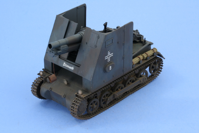
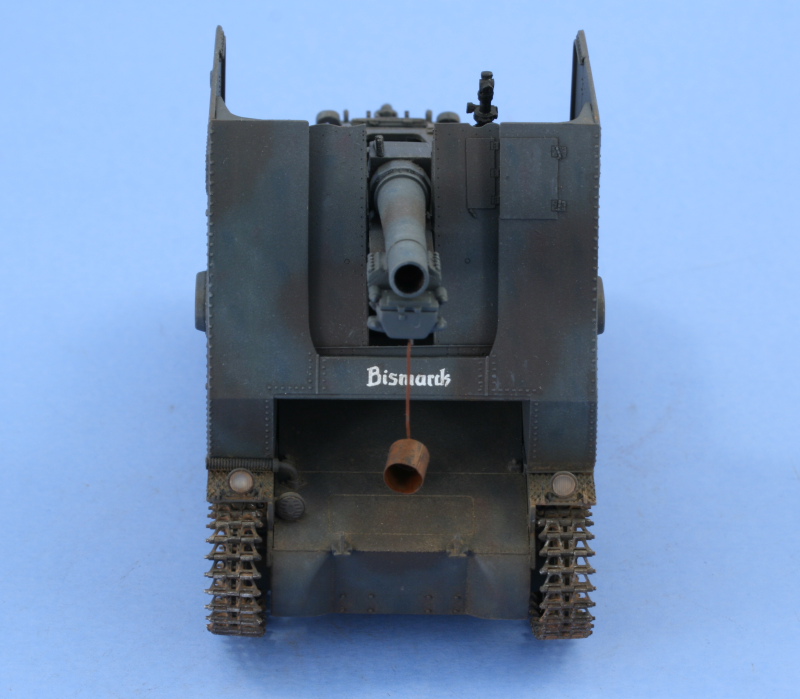
Then the interior received its paint and detailing. As an open-topped vehicle specifically rebuilt into the Bison, the compartment visible to the outside was painted Panzer Gray while the interior areas under the glacis plate were painted with Panzer Interior Buff. Vast majority of this won't be easily visible once the superstructure is in place, but it's there for the curious.

Image

With the interior in place, the rear engine deck was installed along with its access hatches. The DAK version of the kit, which I'd researched previously, includes the original hatches on the sprues as well as the "Tropen" style fitted in N. Africa, so it was easy to get the right deck configuration for a 1940 Bison I. The mated surfaces with the Alan firewall required some sanding to get everything to sit flush and a small touch of putty was needed to close a gap at the rear to achieve the desired fit.

Image

Next up will be work on the superstructure.
Bill Plunk
Posts: 1245
Joined: Wed Sep 28, 2022 10:18 pm

WIP 03-23-2008

Post by Bill Plunk »

With the interior squared away, work now focused on the superstructure. First up was some surgery on the integrated glacis and superstructure unit from the DML kit in order to get just the glacis plate isolated. I used a keyhole saw to remove the original Pz I superstructure and then sanded down the edge flush on the glacis itself where it will meet up with the Bison superstructure.

Image

It was also necessary to remove the little triangular side pieces, this was done with sprue cutters and their edges also sanded smooth. The glacis plate was then installed at the right angle, using the Alan superstructure to test-fit and insure everything would line up properly. The Alan superstructure will fill the gaps and close off the interior once installed, so no need for any styrene extensions for the front. All of the mount holes for the various pioneer tools were filled in with putty since the Bison has a totally different fender layout from the Pz I, the exception being the location of the jack and wire-cutters on the left side.

Image

The superstructure required some modifications to make it accurate, the first being to include a second view port on the right side. This was done by incorporating visor parts from the DML kit and opening up the corresponding hole in the plate to accept the visor on the exterior. The molded on frame for the driver's port was removed and the Eduard items used in its place. Two ejector marks were filled with putty and sanded smooth and the heavy molded on reinforcing brackets were removed and sanded down, the left side has been removed while the right remains to show the difference.

Image

Working with the right side panel first, it was glued into place with the front of the superstructure and allowed to set up. The Eduard bolt strips were installed to recreate the reinforcing brackets along with the angled brace at the top. The locking bar for the side armor flap was installed along with the reinforcing strip for its edge.

Image

The same thing was then done for the left side and the flap for the gun sight installed to the front using the Eduard piece in place of the Alan kit part. The superstructure is dry-fit for now only to test the fit/alignment of the side plates.

Image

Image

Next up will be the SiG 33 itself, it's a monster of a gun for sure!
Bill Plunk
Posts: 1245
Joined: Wed Sep 28, 2022 10:18 pm

WIP 03-30-2008

Post by Bill Plunk »

Didn't make a huge amount of progress this weekend due to spending over 14 hours engaged in the El Paso County Democratic Party Convention on the 29th...the experience left me drained but I was able to get a little bit of time in today.

I needed to revisit a couple of areas on the superstructure from last week as the start point. After checking some reference photos and 1/35 scale drawings, I came to the conclusion that the Eduard set hinges for the exterior superstructure flaps were significantly under-scale so didn't use them, thankfully I'd held off removing the molded-on hinges and was able to verify first. Just goes to show that just because the PE set has it, doesn't mean it's a better item. ;) The second area was the join between the front and side plates, these show as being a tight flush fitting on the actual vehicle, so some careful use of putty and sanding was employed here, taking care to preserve the fine bolt detail in the process...which meant very slow going but eventually got there. This was done on both sides using Squadron white and some sanding twigs cut to an angle.

Image

Next up came the first step in assembling the sIG 33 gun, the incorporation of the Model Point aluminum barrel. The Alan kit has the barrel integrated with the slide mount and a portion of the breech as an old-style split two-part assembly. This meant I needed to remove the barrel from the two halves, accomplished using the same keyhole saw from earlier and sprue cutters. A hole was drilled into the breech area to accept the mount pin on the aluminum barrel and some putty used to fill gaps at both the breech and the recoil slide rests. The rest of the breech was then assembled and installed, including the breech block and lever, and putty and sanding employed to fill the gaps present.

Image

Next up was the recoil tray and mount. The Alan parts here are again a 2-part halves assembly and the fit wasn't all that great. The pins provided on the inside were not sufficient and fortunately the gaps that resulted will be hidden when the gun is installed by the recoil sled. I used the Eduard insert for the rear of the tray to cover the seam and add bolt detail present on the actual gun. I also removed the molded on exterior bolt detail and used the Eduard provided items to create the correct pattern. These PE parts needed to be formed to the angled sides of the tray and bend lines weren't provided, only small notches at the ends to serve as a guide were present. This made it somewhat of a trial and error approach, but eventually they were bent to shape and I used liquid glue to seat them and insure everything was lined up properly. Some light sanding followed especially on the underside.

Image

Image
Bill Plunk
Posts: 1245
Joined: Wed Sep 28, 2022 10:18 pm

WIP 04-05-2008

Post by Bill Plunk »

Working on the gun means working exclusively with the Alan kit parts and this is slow going for a couple of reasons. There are seam lines to be dealt with on every part and the fit is not always the greatest, requiring sanding and multiple test-fits or modifications in many instances to get things to work. I started in today by working on the base of the gun, the Bison I wasn't a sophisticated design, it just took the sIG 33 in its entirety and plopped it on top of the Pz I chassis.

Beginning with the frame of the gun, the two halves had multiple fit problem areas. The molded on pins at the front and rear needed to be removed and the different areas sanded down to get everything to fit properly. I still had a large gap at the front that couldn't be rectified due to the width needed to fit the trunnions on the gun mount. The gap was too large to fill with just putty alone, so a small square of 0.3mm sheet styrene was glued inside the front of the frame to serve as a base. I used a liberal amount of Squadron white and then sanded it smooth, trimming the small bit of the sheet styrene that was sticking up in the process to fill the gap. The front plate with bolt detail from the Eduard set was also added at this point.

Image

With that out of the way, I went on to work with the rest of the details on the frame including mounting the gun itself. The Alan instructions aren't clear on a very key point in terms of installing the side-mounted elevation cylinders, it's essential that they be installed at the same time as the gun as they have mount pins that support the gun and allow it to elevate. The steps don't indicate this, just magically show the gun installed in a later step, so a good thing I kept looking ahead before committing to glue. Most of the Alan provided mounting pins are either too long, too big, or in the wrong place, so in almost every case, anything with a mount pin had it removed and just carefully glued to where it needed to go. I removed the heavy molded on hinges on the trail tool box and replaced them with a couple from the Eduard set that I didn't use on the superstructure side armor. The rudimentary kit-supplied gun sight was replaced with the Tiger Model Designs resin piece as well at this point. That required the careful removal of the mount pin sticking out and sanding it down flush since the TMD part didn't have a hollow mount hole as with the kit part.

Image

Next came one of the bigger challenges, replacing the way over-scale and thick gun-shield with the Eduard supplied item. I carefully assembled the PE shield using my Ausfwerks Fender Bender to bend the various components that had to be fitted front and back and glued them in place using Gator Glue Acrylic PE glue instead of CA gel. The shield was then mounted to the gun itself, a very delicate process since it had to be at just the right angle at the bottom to mate with the support arms as well as fit to the angled supports at the top. I used CA gel to glue to the base mounts first, then glued the styrene top supports in place, then used CA gel again to glue the tops of the shield to the top supports, one side at a time.

Image

Next up will be building up the carriage suspension and installing the mount trays to the fenders.
Bill Plunk
Posts: 1245
Joined: Wed Sep 28, 2022 10:18 pm

WIP 04-06-2008

Post by Bill Plunk »

Continuing on from yesterday, the remaining items for the gun were the wheel suspension. The Alan parts required a substantial amount of work, the mount holes in the carriage weren't the right diameter for the front parts and had to be enlarged using a round needle file. The mount holes for the rear axles were a tapered arrangement, but the tapers on the actual parts weren't correct, so a lot of sanding and test-fitting was necessary before they too could be installed. These served as the mount points for the brake drums and mount points for the actual wheels themselves so it was vital that they fit properly.

Image

I also added some detail via the Eduard set to the inner rims of the gun carriage wheels. The set contains enough to detail both the inner and outer rims but since the outer rims will be pressed up against the superstructure, I only did the inner both to save time and have plenty of spares in case they were needed.

Image

While the suspension elements were drying, test fits showed that the width of the superstructure base where the gun rests was too wide and wouldn't allow for a proper fit to the wheels to accommodate the brake drums and line up properly with the superstructure bulges for the wheel hubs. This meant some very careful sanding was required in order to narrow the top but still keeping the sides intact since those are needed as-is for the exterior front to match up to the hull. This took a lot of back and forth to avoid removing too much and still keep a snug fit, but eventually got it to where it needed to be.

Image

Using the superstructure as a guide, the wheel boxes to hold the gun mount wheels were installed and the rear support bar and side braces installed. I also installed the DML supplied integrated jack/wire cutters mount and the pry-bar on the right side fender. The curved brackets to hold a wicker ammo case were also installed after checking reference photos and determining that the Eduard suggested placement was too far forward.

Image

The left side received its brackets as well for two more wicker cases. The leather straps to secure each case will be added later on once the cases are detailed and installed.

Image

I then test-fitted the gun and superstructure into place to make sure everything was still in the right order. I've kept things modular in the form of the superstructure, the gun, and the lower hull to facilitate painting and will actually install the wheels to the gun and the gun into the mounts permanently later on.

Image

There's some additional detail work needed on the front hull and fenders and the rear hull before things will be ready to paint, but am almost there!
Bill Plunk
Posts: 1245
Joined: Wed Sep 28, 2022 10:18 pm

WIP 04-13-2008

Post by Bill Plunk »

Picking up from last week, I added the Eduard PE belt straps and buckles to the ammo racks on the fenders. Test fits with the TMD wicker cases showed it's possible to leave the straps unsecured for now, this will make it easier to detail paint the cases prior to installation. Then the belts will be secured in place and painted.

Image

The rear hull plate details were next. The Eduard set includes fenders but unfortunately these were designed for the Alan kit and weren't the right dimensions for the DML hull, so I used the DML kit fenders instead. The towing pintle was installed along with the Eduard "dog-chain" retainer as were the tension caps for the idler mounts. The PE chain retainers were given a 3-D look by carefully using two pairs of tweezers and alternately twisting the links in the chain 90 degrees to each other so they didn't look too flat. I had to check references carefully as the Eduard set incorrectly instructed for the end of the chains to be secured to the idler mount extensions when in fact they actually attached to the rear hull plate just above the weld line.

Image

With the back done, time for the front! The trio of headlamps were installed without their lenses as those will get added later after painting and weathering to avoid fogging them. The Eduard set included very nice latches for the front fenders since most Pz I vehicles in combat removed the front mud-guards, although there are pictures with Bison Is with the mudguards in place, I opted to leave them off.

I removed the molded on foot brackets to the superstructure on the Alan parts, a delicate job as they are in very close proximity to fine fine bolt detail. These were trimmed off with a #11 blade and then carefully sanded and the Eduard PE brackets used in their place. The DML brake housing vent hose was also modified by trimming it down and changing its mount angle to 90 degrees. It actually rests on the foot bracket of the superstructure, so I left the superstructure dry-fit so that the hose is at the right height but the superstructure can still slide out for painting before final installation. Last but not least, I also drilled out the mouth of the pipe with a pin vise so it had a hollow end post-surgery.

Image

Then came one of the tedious chores that I'd left deliberately to the very end, the clean-up of the suspension. The Pz I suspension is a complex one and deliberately will leave it un-assembled until after it's painted to allow easier access to the road wheels. All of the road wheels were sanded to remove their fine mold seam and the suspension elements cleaned up. I had a pleasant surprise to discover that my kit included the corrected idler wheels without the rubber rim. When I'd first built the DAK kit, it had the incorrect idlers so I assumed that when I bought this second one, it too would need the correction. The DML instructions don't indicate that these parts are there, but they are included so I used them instead of the Lion Marc idlers. The DML instructions don't have assembly directions so I had to figure it out myself...not an easy task as they provide 2 different styles of corrected idlers, so getting it straight took a bit of research and head-scratching.

Image

Every thing's now ready for paintwork to begin, but that will have to wait for next weekend.
Bill Plunk
Posts: 1245
Joined: Wed Sep 28, 2022 10:18 pm

WIP 04-20-2008

Post by Bill Plunk »

Finally made it to the paint stage, and to prepare for it I needed to first mask off the interior using blue painter's tape to protect it. This was a bit tricky to arrange because of the radio and the tight spaces on the interior but eventually got it all set. To facilitate painting, the superstructure, the hull, and the gun minus its wheels were treated as sub-assemblies. To protect the mount points for the suspension and avoid the need to scrape paint later on, small amounts of blue tack poster putty were used and the idler mounts were also temporarily mounted using the same material.

Image

Everything was primed using MM enamel Italian Dark Brown and then given a base coat of MM Panzer Schwarzgrau in the form of very light mist coats to slowly build up to the desired tone.

Image

While most people just assume that straight Panzer Gray is the order of the day for any early war vehicles up until the switch to Dunkelgelb in 1943, that's true only for the time frame of July 1940 onward. For the Polish, Norwegian, and Battle of France campaigns, the standing order was for vehicles to be 2/3 Panzer Gray and 1/3 Dark Brown. I used MM Schokoladenbraun for my Dark Brown pattern, using a color plate in the Panzerwaffe Vol. 2 as a rough guide. In most period photos, especially if the vehicle is wearing any kind of dust, it's very hard to distinguish the Dark Brown and you can see why...the contrast level between the two dark colors isn't very high even in color.

Image

To provide some color variation as a foundation for weathering, I very lightly sprayed some Panzer Gray mixed with Light Gray to the Panzer Gray areas. This will get blended in more with later steps

Image

With that out of the way, it was time to add the suspension and work on the details. The wicker ammunition cases were installed and secured in place with the straps painted and detailed as well. For the wicker cases, I painted them my home-made mix of "wood" color and then gave them a careful dusting with black pastel to pull out their very nicely cast details. The headlights were treated with some Silver and their clear lenses will be installed much later on once weathering is completed. I also installed the gun permanently into place along with the superstructure once all the fender items were installed. Getting the carriage wheels to fit properly was a fun exercise since they are a snug fit into the bulges on the superstructure!

Image

The right side details also got some attention with the wire cutter painted and detailed along with the muffler.

Image

The gun itself, prior to installation, received some detail painting as well. The breech block was detailed using Steel and the breech lever and gun sight painted and detailed as well along with the side elevation wheels on the gun carriage. The recoil sled rails were carefully dry-brushed with Steel and then dusted with black artist pastels for their bare metal finish. The antenna mount base was painted with Aircraft Interior Black but will not receive a full-size antenna. After checking several period photos the mounts are there on several but they don't show the aerial in place...not sure if that was due to the crew decision regarding work space or the nature of the fighting in France not making it as essential. In later reference photos for the Balkans and Eastern Front, the aerial is prominent so all depends I guess.

Image

Final remaining task is to assemble the MK tracks and get them ready for installation, a slow piece of work but one that will be worth it in the end.
Bill Plunk
Posts: 1245
Joined: Wed Sep 28, 2022 10:18 pm

WIP 04-27-2008

Post by Bill Plunk »

Most of the week was spent getting the tracks together. The MK set for the Pz I-B has one pin already molded in place with a second separate pin used to link them together and keep things workable. 101 links were used on both sides and, as anyone who's worked on Pz I's knows, they are tiny! Each link needed to have 3 contact points cleaned up and once assembled, were base coated with MM Metalizer Non-buffing Gunmetal. This was followed with dry-brushed Steel and a wash of Burnt Umber. Because of the way the links are secured together, they were joined into a single workable loop prior to installation.

Image

Both tracks, along with the sprockets and idlers, were then installed. The sprockets and idlers had their contact surfaces dry-brushed with Steel and Burnt Umber to "pre-weather" them along with the lower hull sides. I also used small amounts of glue on the return rollers and road wheels to tack the tracks into place. The MK sets have a tendency to shift around a bit if left to their own devices, so rather than have to check them every time the vehicle is moved or photographed, it's better to have them secured in place.

Image

The tracks were the final construction element, so the next step was to apply a coat of Future via airbrush and apply the decals. The Bison Decals set suggested some tactical markings for the superstructure sides but checking reference photos of "Bismarck" shows they weren't used. It's a good thing I had the Bison set for use as the Alan-supplied decals disintegrated when I tried to use the elevation/firing table for the inside of the right side superstructure panel.

Image

A second coat of Future was applied to seal the decals and every thing's now set for the weathering to begin...but that will have to wait for next weekend.
Bill Plunk
Posts: 1245
Joined: Wed Sep 28, 2022 10:18 pm

Completion 05-03-2008

Post by Bill Plunk »

The weathering process began with the application of dot filters using the small glass bottle Testor's flat enamel paints. Small dots of Sea Blue, Red, Yellow, and White were applied with a spotter brush. A round 0 sable brush dampened with thinner was then used to draw the dots together in a downward motion to blend them all together.

Image

Once the dot treatment was completed, a pin wash of Burnt Umber was applied to add some depth. The model received a sealing coat of Testor's Lusterless Flat in the spray can and the headlight lenses were installed from the DML kit.

Image

The flat coat restores the "tooth" to the finish, and some of the lightened panzer gray mix that I'd applied previously by airbrush was dry-brushed on the raised detail to further compliment the washes and weathering and further heighten the depth and detail. I also installed the leather muzzle cap provided in the Eduard item. The cap is a single PE piece that needed to be annealed and formed into circular shape, which took some care as the circular end cap is attached to the sides via a small metal tab. Some careful use of CA gel and a brush handle did the trick. The cap was then painted with MM Leather, given a very light wash of enamel Gunmetal, and dry-brushed with Burnt Umber. The small strap was attached in place to the D hook under the recoil sled, also an Eduard-supplied item, and is free-hanging just like on the real vehicle.

Image

The final step in the weathering came in the form of applying a mixture of Mig pigments Europe Dust and Dark Mud together using ordinary tap water and brush. The mixture was allowed to air dry over the course of an hour or so.

Image

Once dried, a combination of stiff bristled brushes and q-tips (both wet and dry) were used to remove the excess and get the look to where I wanted it. Another very light coat of Lusterless Flat was used to tone down the pigment effect a bit and seal it in place. The tracks were very lightly dry-brushed with Steel with a small amount of black artist pastel added to tone down some of the too-bright areas.

Image

Satisfied with the overall look, it was off to the photo-booth for the final shots.

Image

Image

Image

Image
Post Reply