
Tristar Pzkpfw 38(t) Ausf E/F (2008)
-
Bill Plunk
- Posts: 1245
- Joined: Wed Sep 28, 2022 10:18 pm
Tristar Pzkpfw 38(t) Ausf E/F (2008)
Build log for Tristar's 1/35 kit #020 with Aber replacement barrel, LionMarc MGs, and Model Kasten tracks.
-
Bill Plunk
- Posts: 1245
- Joined: Wed Sep 28, 2022 10:18 pm
WIP 10-06-2008
I've been wanting to tackle one of the Tristar family of 38t vehicles for a while, so figured it was time.
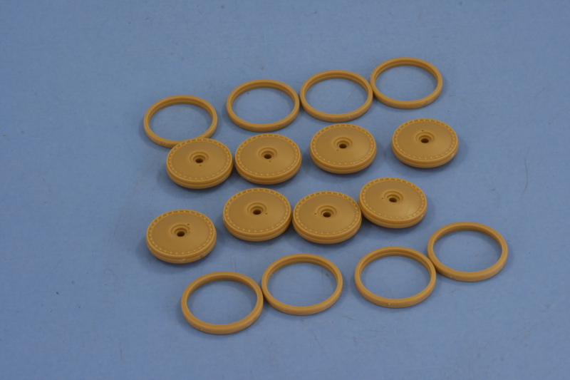
Work started where it often does, with the road wheels and suspension. Step 1 in the instructions is actually broken down into 4 different steps and I started in by removing the 8 large road wheels and their separate rubber rims from the sprues. The rubber rims had a slight seam that was removed via sanding with a sanding twig. These were set off to the side for now in a clear plastic bin for safekeeping.
Next up came the suspension elements. The leaf springs had their seam carefully removed with a knife blade and then were glued in place to the suspension plate along with a small square retaining piece on the bottom. The suspension elements are designed to be semi-workable if care is taken with the glue. This is particularly true of the individual swing arms, so long as glue is very sparingly applied only to the post of the round cap, each arm will remain fully articulated when its all said and done. Each suspension element consists of 7 parts for a grand total of 28 parts to complete this sub-assembly.

Next up came the assembly of the idlers and sprockets. I discovered that one of the original sprocket halves in the Tristar kit had been badly damaged so the sprockets will be replaced with Model Kasten items from their A-9 set that I had on hand as spares. This will require some modification to the mount points later on to accommodate. The idlers were also assembled and left movable on the idler arm by means of a very small plastic washer that also has to be very carefully glued in place to achieve this. Last but not least, I assembled the mounts and hubs for the return rollers, leaving their separate rubber rims off to the side for now.

The 4th sub-assembly, which I haven't yet decided on when exactly to complete, deals with mounting the road wheels to the suspension elements and leaving them movable as well via a small hexagonal nut under the main cap. That will take some consideration as it has positives and negatives associated with it, so I'll wait until I have the hull constructed first before committing.
Work started where it often does, with the road wheels and suspension. Step 1 in the instructions is actually broken down into 4 different steps and I started in by removing the 8 large road wheels and their separate rubber rims from the sprues. The rubber rims had a slight seam that was removed via sanding with a sanding twig. These were set off to the side for now in a clear plastic bin for safekeeping.
Next up came the suspension elements. The leaf springs had their seam carefully removed with a knife blade and then were glued in place to the suspension plate along with a small square retaining piece on the bottom. The suspension elements are designed to be semi-workable if care is taken with the glue. This is particularly true of the individual swing arms, so long as glue is very sparingly applied only to the post of the round cap, each arm will remain fully articulated when its all said and done. Each suspension element consists of 7 parts for a grand total of 28 parts to complete this sub-assembly.
Next up came the assembly of the idlers and sprockets. I discovered that one of the original sprocket halves in the Tristar kit had been badly damaged so the sprockets will be replaced with Model Kasten items from their A-9 set that I had on hand as spares. This will require some modification to the mount points later on to accommodate. The idlers were also assembled and left movable on the idler arm by means of a very small plastic washer that also has to be very carefully glued in place to achieve this. Last but not least, I assembled the mounts and hubs for the return rollers, leaving their separate rubber rims off to the side for now.
The 4th sub-assembly, which I haven't yet decided on when exactly to complete, deals with mounting the road wheels to the suspension elements and leaving them movable as well via a small hexagonal nut under the main cap. That will take some consideration as it has positives and negatives associated with it, so I'll wait until I have the hull constructed first before committing.
-
Bill Plunk
- Posts: 1245
- Joined: Wed Sep 28, 2022 10:18 pm
WIP 10-12-2008
I have to say that building this little kit has been a blast, so much so that I had to repeatedly remind myself to stop and take photos! I made a lot of progress yesterday and today, so this is a rather large update as a result.
I resumed work from last weekend by tackling Step 2 and assembling the lower hull. Tristar uses a panel approach to do this vs. a traditional tub, so getting a good alignment is key. I used the rear hull C-3 and the glacis C-1 along with careful amounts of both regular and liquid glue along the way.

Once that had set up, I installed the front tow hooks and the transmission access hatch and proceeded on to Step 3. This step calls for the installation of the various different suspension elements, I installed the suspension bogies from Step 1 first and made sure they were aligned properly and glued in solid before adding the road wheels themselves. The reason for this is that the road wheels sit a bit loose on each of the swing arms, so before securing the in place with their hex nuts and hub caps, it was essential that the bogies be square. I also installed the final drive housings but first had to modify them to accommodate the MK sprockets. I removed the molded on stubs from the hull panels as well as the original mount posts and drilled out the outer cover to accommodate the MK mount pins. Since the suspension arms are able to swing freely, it's no problem adding the sprockets and idlers later in the proper position.

Step 4 deals with the front hull superstructure plate. I added in the driver and radio operator visors, positioning the driver's in the open position and added the armored glass from the inside. For the hull MG, I used the kit supplied base and ball mount and combined that with the Lion Marc barrel and tray. The LM barrel's mount pin was too long to fit properly, so that was trimmed down with a pair of side cutters and installed with CA gel. The tray came next along with the preformed brass gun sight from the LM set.

The rest of this step called for the installation of the front plate along with the fenders and front bracket mounts.

Step 5 calls for the installation of all the fender gear and front hull details, but I skipped that for now and went on to Step 6 which added the rest of the upper hull framework first to be sure everything fit right. The fit of the radio operator's hatch was very tight and created a small gap with the front plate that some putty fixed right up.

I went on to Step 7, deciding to add details front to back in order to avoid too much handling of different areas and minimize potential for breakage along the way. Step 7 added all of the necessary details to the rear hull and the instructions contain an option here that they don't call out very well. This is in regards to the idler tension covers, you have two choices in parts E-34 or E-33, but the instructions show one of each being installed which is not correct. Since I'm going for a Crimea vehicle, I opted for the later style armored covers, E-34.

Moving up the right side, I returned to Step 5 and constructed and installed the grouser box and jack, using the kit-supplied PE straps to secure the jack in place. The jack block was also installed along with the axe and wire cutters. The kit provides PE handles to add to the molded-on clamps, a nice easy way to achieve some detail IMHO.

Next up came the front hull, I installed the driver's guide loop and the front hull spare track holder. I constructed the spare track run using 7 links from the MK set. The fender Notek light and antenna mount were also installed. I drilled out the base of the antenna mount and used a Lion Marc tapered brass antenna glued in place with CA gel. I also realized at this point that I hadn't correctly installed the fenders in the earlier step in relation to how they sat on the front hull and final drive cover, so I carefully used liquid glue to free them and repositioned them in the correct position.

On the left hand side, I installed the kit provided PE straps with CA gel and the installed the shovel, pick axe, crow bar, and sledge hammer. The pick axe has a very delicate mount point on the side of the hull, so I let that dry solid first before properly positioning the shovel handle at rest over the armored vent cover in a later step.

Rejoining the instructions with Step 8, work started on the turret. First up was the construction and installation of the main gun and MG. Instead of the one-piece kit barrel, I used the Aber replacement. It was a straight forward swap out, the kit barrel was cut off with sprue cutters under the recoil cylinder and a hole drilled with a pin vise to take the mount pin on the Aber barrel. The barrel was glued in with CA gel and the rest of the parts for the breech assembled to provide a counter-weight once installed in the turret. The Lion Marc set was used here to replace the turret MG in the same process as with the hull MG.

The next part in Step 8 dealt with construction of the turret roof and the commander's cupola. The cupola is a multi-part affair including clear pieces for the vision blocks. I decided to keep things simple and install the commander's hatch in the closed position.

The rest of the turret was constructed and Tristar again uses a panel arrangement similar to that on the hull. I installed the side panels first and let them set before adding the rear and then finally the top and front. I also fixed the MG in position using some carefully applied liquid glue to prevent it from rolling around and potentially losing its gun sight.

I test fit the turret to the hull and it's a very very tight fit. I decided to remove the "ears" that were provided in the base and will just rely on the tight friction fit for final installation. There are a few small details that I need to add before painting such as the PE latches for the radio operator's hatch, the turret sight cover, and the spare track runs for the glacis, but otherwise major construction is complete.

I resumed work from last weekend by tackling Step 2 and assembling the lower hull. Tristar uses a panel approach to do this vs. a traditional tub, so getting a good alignment is key. I used the rear hull C-3 and the glacis C-1 along with careful amounts of both regular and liquid glue along the way.
Once that had set up, I installed the front tow hooks and the transmission access hatch and proceeded on to Step 3. This step calls for the installation of the various different suspension elements, I installed the suspension bogies from Step 1 first and made sure they were aligned properly and glued in solid before adding the road wheels themselves. The reason for this is that the road wheels sit a bit loose on each of the swing arms, so before securing the in place with their hex nuts and hub caps, it was essential that the bogies be square. I also installed the final drive housings but first had to modify them to accommodate the MK sprockets. I removed the molded on stubs from the hull panels as well as the original mount posts and drilled out the outer cover to accommodate the MK mount pins. Since the suspension arms are able to swing freely, it's no problem adding the sprockets and idlers later in the proper position.
Step 4 deals with the front hull superstructure plate. I added in the driver and radio operator visors, positioning the driver's in the open position and added the armored glass from the inside. For the hull MG, I used the kit supplied base and ball mount and combined that with the Lion Marc barrel and tray. The LM barrel's mount pin was too long to fit properly, so that was trimmed down with a pair of side cutters and installed with CA gel. The tray came next along with the preformed brass gun sight from the LM set.
The rest of this step called for the installation of the front plate along with the fenders and front bracket mounts.
Step 5 calls for the installation of all the fender gear and front hull details, but I skipped that for now and went on to Step 6 which added the rest of the upper hull framework first to be sure everything fit right. The fit of the radio operator's hatch was very tight and created a small gap with the front plate that some putty fixed right up.
I went on to Step 7, deciding to add details front to back in order to avoid too much handling of different areas and minimize potential for breakage along the way. Step 7 added all of the necessary details to the rear hull and the instructions contain an option here that they don't call out very well. This is in regards to the idler tension covers, you have two choices in parts E-34 or E-33, but the instructions show one of each being installed which is not correct. Since I'm going for a Crimea vehicle, I opted for the later style armored covers, E-34.
Moving up the right side, I returned to Step 5 and constructed and installed the grouser box and jack, using the kit-supplied PE straps to secure the jack in place. The jack block was also installed along with the axe and wire cutters. The kit provides PE handles to add to the molded-on clamps, a nice easy way to achieve some detail IMHO.
Next up came the front hull, I installed the driver's guide loop and the front hull spare track holder. I constructed the spare track run using 7 links from the MK set. The fender Notek light and antenna mount were also installed. I drilled out the base of the antenna mount and used a Lion Marc tapered brass antenna glued in place with CA gel. I also realized at this point that I hadn't correctly installed the fenders in the earlier step in relation to how they sat on the front hull and final drive cover, so I carefully used liquid glue to free them and repositioned them in the correct position.
On the left hand side, I installed the kit provided PE straps with CA gel and the installed the shovel, pick axe, crow bar, and sledge hammer. The pick axe has a very delicate mount point on the side of the hull, so I let that dry solid first before properly positioning the shovel handle at rest over the armored vent cover in a later step.
Rejoining the instructions with Step 8, work started on the turret. First up was the construction and installation of the main gun and MG. Instead of the one-piece kit barrel, I used the Aber replacement. It was a straight forward swap out, the kit barrel was cut off with sprue cutters under the recoil cylinder and a hole drilled with a pin vise to take the mount pin on the Aber barrel. The barrel was glued in with CA gel and the rest of the parts for the breech assembled to provide a counter-weight once installed in the turret. The Lion Marc set was used here to replace the turret MG in the same process as with the hull MG.
The next part in Step 8 dealt with construction of the turret roof and the commander's cupola. The cupola is a multi-part affair including clear pieces for the vision blocks. I decided to keep things simple and install the commander's hatch in the closed position.
The rest of the turret was constructed and Tristar again uses a panel arrangement similar to that on the hull. I installed the side panels first and let them set before adding the rear and then finally the top and front. I also fixed the MG in position using some carefully applied liquid glue to prevent it from rolling around and potentially losing its gun sight.
I test fit the turret to the hull and it's a very very tight fit. I decided to remove the "ears" that were provided in the base and will just rely on the tight friction fit for final installation. There are a few small details that I need to add before painting such as the PE latches for the radio operator's hatch, the turret sight cover, and the spare track runs for the glacis, but otherwise major construction is complete.
-
Bill Plunk
- Posts: 1245
- Joined: Wed Sep 28, 2022 10:18 pm
WIP 10-18-2008
Work continued today with the addition of the PE parts for the radio operator's hatch latch and the glacis spare track holders. I elected to leave these empty as I had an extremely hard time getting links to sit here properly due to the confines between the transmission hatch lip and the fenders. It would've been a lot easier to install these much earlier on in the assembly process as it requires removal of rivets on both ends, a much more difficult task when all the plates are installed at this stage. I'm not sure why Tristar left this to the very end, but there you go. I also got tired of wrestling with the turret and used a round needle file to sand down slightly the inside of the turret ring to provide a slightly looser fit and allow the turret to rotate a bit more easily while still retaining a good friction fit since I'd removed the ears earlier on.

With that out of the way, I prepped everything for painting by using small amounts of poster blue tack putty to mask off the clear pieces in the cupola and the driver's visor, using a toothpick to carefully push the putty down into the vision blocks. The same blue tack was also used to mask off the mount points for the sprockets and idlers and it was off to the paint booth. I laid down a primer coat of Italian Dark Brown to start off and insure I didn't have any areas of bare plastic. I deliberately left the rubber portions of the road wheels in place during this stage to serve as a natural mask for the wheels themselves.

Since I'm laying down a 2-tone camo pattern for the Crimea scheme, I decided against an overall coat of Panzer Schwarzgrau and instead only sprayed it where I wanted it in the pattern. This had the added benefit of allowing me to sketch out the overall pattern of sorts and still provide room to adjust if needed.

Next came the dunkelgelb portion of the pattern. I used an 80/20 mix of Dunkelgelb/Light Gray and outlined the areas against the Panzer Gray and then filled in the gaps. My original layout had a bit too much of the dunkelgelb so I went back over things a bit with the Panzer Gray and also corrected some inevitable areas of over spray that resulted. I also painted the rubber rims, first popping them off and securing them to a strip of masking tape and then spraying them with Gunmetal, taking care to avoid getting paint on the inner surfaces. Somewhere along the way I managed to lose the gun sight on the turret MG, will have to see if I can improvise some sort of replacement since I'd already used up the spare provided in the Lion Marc set earlier.

Next up will be dealing with the various hull details and getting the tracks done and installed.
With that out of the way, I prepped everything for painting by using small amounts of poster blue tack putty to mask off the clear pieces in the cupola and the driver's visor, using a toothpick to carefully push the putty down into the vision blocks. The same blue tack was also used to mask off the mount points for the sprockets and idlers and it was off to the paint booth. I laid down a primer coat of Italian Dark Brown to start off and insure I didn't have any areas of bare plastic. I deliberately left the rubber portions of the road wheels in place during this stage to serve as a natural mask for the wheels themselves.
Since I'm laying down a 2-tone camo pattern for the Crimea scheme, I decided against an overall coat of Panzer Schwarzgrau and instead only sprayed it where I wanted it in the pattern. This had the added benefit of allowing me to sketch out the overall pattern of sorts and still provide room to adjust if needed.
Next came the dunkelgelb portion of the pattern. I used an 80/20 mix of Dunkelgelb/Light Gray and outlined the areas against the Panzer Gray and then filled in the gaps. My original layout had a bit too much of the dunkelgelb so I went back over things a bit with the Panzer Gray and also corrected some inevitable areas of over spray that resulted. I also painted the rubber rims, first popping them off and securing them to a strip of masking tape and then spraying them with Gunmetal, taking care to avoid getting paint on the inner surfaces. Somewhere along the way I managed to lose the gun sight on the turret MG, will have to see if I can improvise some sort of replacement since I'd already used up the spare provided in the Lion Marc set earlier.
Next up will be dealing with the various hull details and getting the tracks done and installed.
-
Bill Plunk
- Posts: 1245
- Joined: Wed Sep 28, 2022 10:18 pm
WIP 10-19-2008
Continuing on from yesterday's efforts, the tracks were up next. I'm replacing the kit indy links with the set from Model Kasten. The MK set comes with a small jig and the links are arranged 2 to a sprue with 4 connection points that need to be cleaned up on each link. The links are joined together with pins just like on the real tracks. A small touch of glue to the pins, insert them in, then twist off the handle and voila! workable tracks. The MK instructions suggest 95-96 links per side but this is too many, 93 is all that is needed.


I also spent some time working on the various details on the hull. The tools were detailed with non-buffing Metalizer Gunmetal for their metal portions and lightly dry-brushed with Steel. The wood handles were painted with my own mix of "wood" color followed by a light wash of Leather. A heavier wash was used on the jack block to give it a deeper look. The exhaust was also detailed, a base coat of the same Metalizer Gunmetal was applied followed by a wash of Rust, then a second wash of Burnt Umber along with some light dry brushing of Burnt Umber in various places. The spare track run on the hull front and the 2 spare links on the fender were also detailed along with the 2 MGs and the antenna mount and rod. Rounding things out a bit, I also installed the rubber rims on the return rollers.


Next steps will be to paint and install the tracks and then begin the weathering process.
I also spent some time working on the various details on the hull. The tools were detailed with non-buffing Metalizer Gunmetal for their metal portions and lightly dry-brushed with Steel. The wood handles were painted with my own mix of "wood" color followed by a light wash of Leather. A heavier wash was used on the jack block to give it a deeper look. The exhaust was also detailed, a base coat of the same Metalizer Gunmetal was applied followed by a wash of Rust, then a second wash of Burnt Umber along with some light dry brushing of Burnt Umber in various places. The spare track run on the hull front and the 2 spare links on the fender were also detailed along with the 2 MGs and the antenna mount and rod. Rounding things out a bit, I also installed the rubber rims on the return rollers.
Next steps will be to paint and install the tracks and then begin the weathering process.
-
Bill Plunk
- Posts: 1245
- Joined: Wed Sep 28, 2022 10:18 pm
WIP 10-23-2008
Much progress has been made since the last update with the majority of attention being devoted to the tracks. I prepped them for painting by attaching them to lengths of masking tape since I will paint them by airbrush.

I base coated them first with Flat Black as a primer/protection coat since the follow-on application is the lacquer-based Non-Buffing Metalizer Gunmetal and it can be a little "hot" for the MK plastic and I didn't want to run the risk of damaging the pins. The metalizer was applied by air brush as well and then both runs set aside for a bit to dry.

The next step was to dry brush them with Steel to accentuate the "metal" look/feel. The Metalizer is ideal for this since it has tiny little flakes in the paint that are super attractive for dry brushed paint. I used a round 0 sable brush and a paper towel, using the paper towel to blot off excess paint and also to test when just enough was on the brush to show up on the paper towel pattern.


The next step was to use the same brush and apply a wash of Raw Umber (enamel not oils) to the tracks. This is a wash I keep around for this and other things, so the bottle is a little "crusty" looking but the mix is about 90/10 Thinner/Paint. Because the Metalizer is very sensitive to thinners, the wash has to be applied in single light passes without allowing the brush to "grab" or it will lift up the Metalizer in the process. When done right, it mutes and blends the previous dry brushed Steel. The goal here is to provide a foundation for later weathering with pigments and not achieve a "final" look.


With that out of the way, it was time to mount the tracks on the vehicle. This turned out to be a little trickier than I anticipated due to the idler being "loose". Even when glued into position, I had to hold it for a couple of minutes at the desired tension, taking care at the same time not to allow the idler to "toe" in or out. I also discovered that I had a slight misalignment in one of the sprockets, so I had to take it apart with liquid glue and carefully reassemble it to get the teeth to align properly.
I also "pre weathered" the idler and sprocket with some dry brushed Steel followed by dry brushed Burnt Umber as a foundation for later pigment and washes. The road wheels received some Burnt Umber dry brushing as well to represent some scuffing/scraping on their surfaces.
Once the idlers had set up nice and hard, I applied some liquid glue to the road wheels and swing arms from the back sides to insure they would stay square. After that had dried, I used some additional liquid glue to tack the links into place on the road wheels, return rollers, idlers, and sprockets to retain the sag in a "permanent" position.


Everything received a sealing coat of Future and the decal markings were applied. The markings for this particular scheme were simple, just a set of turret numbers for either side and the balkenkreuze as well as a 20th Pz Div symbol on the rear. The decals were treated with Walther's Solvaset to insure they snugged down tight and a second coat of Future applied to seal them in place. This will cure overnight and I can start the weathering process tomorrow.

I base coated them first with Flat Black as a primer/protection coat since the follow-on application is the lacquer-based Non-Buffing Metalizer Gunmetal and it can be a little "hot" for the MK plastic and I didn't want to run the risk of damaging the pins. The metalizer was applied by air brush as well and then both runs set aside for a bit to dry.
The next step was to dry brush them with Steel to accentuate the "metal" look/feel. The Metalizer is ideal for this since it has tiny little flakes in the paint that are super attractive for dry brushed paint. I used a round 0 sable brush and a paper towel, using the paper towel to blot off excess paint and also to test when just enough was on the brush to show up on the paper towel pattern.
The next step was to use the same brush and apply a wash of Raw Umber (enamel not oils) to the tracks. This is a wash I keep around for this and other things, so the bottle is a little "crusty" looking but the mix is about 90/10 Thinner/Paint. Because the Metalizer is very sensitive to thinners, the wash has to be applied in single light passes without allowing the brush to "grab" or it will lift up the Metalizer in the process. When done right, it mutes and blends the previous dry brushed Steel. The goal here is to provide a foundation for later weathering with pigments and not achieve a "final" look.
With that out of the way, it was time to mount the tracks on the vehicle. This turned out to be a little trickier than I anticipated due to the idler being "loose". Even when glued into position, I had to hold it for a couple of minutes at the desired tension, taking care at the same time not to allow the idler to "toe" in or out. I also discovered that I had a slight misalignment in one of the sprockets, so I had to take it apart with liquid glue and carefully reassemble it to get the teeth to align properly.
I also "pre weathered" the idler and sprocket with some dry brushed Steel followed by dry brushed Burnt Umber as a foundation for later pigment and washes. The road wheels received some Burnt Umber dry brushing as well to represent some scuffing/scraping on their surfaces.
Once the idlers had set up nice and hard, I applied some liquid glue to the road wheels and swing arms from the back sides to insure they would stay square. After that had dried, I used some additional liquid glue to tack the links into place on the road wheels, return rollers, idlers, and sprockets to retain the sag in a "permanent" position.
Everything received a sealing coat of Future and the decal markings were applied. The markings for this particular scheme were simple, just a set of turret numbers for either side and the balkenkreuze as well as a 20th Pz Div symbol on the rear. The decals were treated with Walther's Solvaset to insure they snugged down tight and a second coat of Future applied to seal them in place. This will cure overnight and I can start the weathering process tomorrow.
-
Bill Plunk
- Posts: 1245
- Joined: Wed Sep 28, 2022 10:18 pm
WIP 10-25-2008
I began the weathering process by first applying a dot filter over the paint scheme. The dunkelgelb areas received a mix of dots of Flat White and Flat Yellow for their fading/variation and the panzer grau areas received a mix of Flat Sea Blue and Flat White. The dots were applied with small spotter brushes and then carefully blended together using a square #4 brush dampened with thinner. The key here is to go slow and work one section at a time and not get too aggressive with the thinner and slowly blend the dots into the overall scheme.


The next step was the application of a pin wash of Burnt Umber enamel to all the panel lines, raised detail, and the numerous rivet heads. This was applied with a pointed 10/0 brush and then the excess removed and adjusted with a clean round sable brush and thinner.

I wanted to achieve a little more variation to the dunkelgelb areas so I added some dots of Raw Sienna to those areas only, using the same spotter brush as before.

Since I'm talking about brushes a lot, I thought I should at least show a pic of the brush I use to blend the dots. The goal is the same as any filter approach, you want to leave just the barest hint behind to tint or alter the underlying coat colors. The square #4 brush is ideal for this as it will "hold" the paint better at the tips than a round brush and offers much more control in the process of how little or how much you leave behind. It can also be turned lengthwise and used to produce some very fine streaking effects to where desired. I touch the brush to a clean paper towel after dipping the brush into the clean thinner to insure it isn't "flooded" and only dampened and then use very light repeated strokes to blend away the dots of paint.

Applying the Raw Sienna dots at this stage and blending them in also allowed for some additional blending and fine tuning with the previous pin wash. The effects achieved are subtle but when viewed up-close with the macro lens, you can see just how much the underlying base coat has been varied and layered in the process.

Next up will be a sealing flat coat and then the work with the pigments will begin.
The next step was the application of a pin wash of Burnt Umber enamel to all the panel lines, raised detail, and the numerous rivet heads. This was applied with a pointed 10/0 brush and then the excess removed and adjusted with a clean round sable brush and thinner.
I wanted to achieve a little more variation to the dunkelgelb areas so I added some dots of Raw Sienna to those areas only, using the same spotter brush as before.
Since I'm talking about brushes a lot, I thought I should at least show a pic of the brush I use to blend the dots. The goal is the same as any filter approach, you want to leave just the barest hint behind to tint or alter the underlying coat colors. The square #4 brush is ideal for this as it will "hold" the paint better at the tips than a round brush and offers much more control in the process of how little or how much you leave behind. It can also be turned lengthwise and used to produce some very fine streaking effects to where desired. I touch the brush to a clean paper towel after dipping the brush into the clean thinner to insure it isn't "flooded" and only dampened and then use very light repeated strokes to blend away the dots of paint.
Applying the Raw Sienna dots at this stage and blending them in also allowed for some additional blending and fine tuning with the previous pin wash. The effects achieved are subtle but when viewed up-close with the macro lens, you can see just how much the underlying base coat has been varied and layered in the process.
Next up will be a sealing flat coat and then the work with the pigments will begin.
-
Bill Plunk
- Posts: 1245
- Joined: Wed Sep 28, 2022 10:18 pm
WIP 10-26-2008
The final stage of the weathering process involves a pigment treatment for the suspension and tracks. I used about a 50-50 mix of Mig Pigments Europe Dust and Dark Mud. I mixed the powder in dry form in an old prescription bottle cap first to get things going.

I then added some ordinary tap water to create a wet mixture that was applied using a large round sable brush. This wet mixture was then allowed to air dry for about an hour or so.

The next step was to remove any excess pigment that had built up in the wet application. I used a series of square and round stiff bristled brushes to do this, wearing a dust mask the whole time to avoid inhaling the fine powder that results.

Next I used several Q-tips and some clean water to further remove and blend in the pigments. Any stray fibers that pulled loose were removed carefully with a pair of tweezers.

The last step was a very light dry-brushing on the contact points of the track faces to bring that back out a bit more. I also lightly dry brushed some panzer gray and dunkelgelb on the vehicle markings to add just a touch more to their look. That's it for this one, all that remains is some time in the photo booth for the completed shots before taking its place in the display case.

I then added some ordinary tap water to create a wet mixture that was applied using a large round sable brush. This wet mixture was then allowed to air dry for about an hour or so.
The next step was to remove any excess pigment that had built up in the wet application. I used a series of square and round stiff bristled brushes to do this, wearing a dust mask the whole time to avoid inhaling the fine powder that results.
Next I used several Q-tips and some clean water to further remove and blend in the pigments. Any stray fibers that pulled loose were removed carefully with a pair of tweezers.
The last step was a very light dry-brushing on the contact points of the track faces to bring that back out a bit more. I also lightly dry brushed some panzer gray and dunkelgelb on the vehicle markings to add just a touch more to their look. That's it for this one, all that remains is some time in the photo booth for the completed shots before taking its place in the display case.
-
Bill Plunk
- Posts: 1245
- Joined: Wed Sep 28, 2022 10:18 pm
Completion 10-26-2008
And now for the finished shots:


-
Bill Plunk
- Posts: 1245
- Joined: Wed Sep 28, 2022 10:18 pm
Publication January 2009
This build is also featured in the Scale Military Modeler International January 2009 issue on pp 70-72.

