
Tamiya Mobelwagen Sdkfz 161/3 3.7cm Flak 43 (2008)
-
Bill Plunk
- Posts: 1245
- Joined: Wed Sep 28, 2022 10:18 pm
Tamiya Mobelwagen Sdkfz 161/3 3.7cm Flak 43 (2008)
Build log for Tamiya's kit #35-237 1/35 Mobelwagen with ModelKasten replacement tracks, Eduard PE, and Lion Roar Flak 43 3.7cm kit.
-
Bill Plunk
- Posts: 1245
- Joined: Wed Sep 28, 2022 10:18 pm
WIP 07-27-2008
Work began today on a new project, one that I've wanted to do for a while but held off on for a variety of reasons. Lion Roar's recent release of the Flak 43 3.7cm kit is what finally pushed me into the build though, so here goes.
Since this is a multi-media build and kitbash/combination exercise, the kit instructions steps will not necessarily be followed to the letter. I started with the lower hull and suspension first, installing the bogies, bump stops and final drive housings as called for in Steps 1 and 3 but left off the return rollers for the time being.

The rear hull plate had it's various elements installed and I used the Eduard PE items to replace the fuel filler cap since it included the retaining chain. The chain was given a 3-D look by carefully bending the flat links 90 degrees to each other using two pairs of tweezers and working one link at a time. PE mounts for the base of the exhaust covers were also added and the rear plate installed to the lower hull.


Next came the road wheels, return rollers, sprockets, and idlers. The kit provides the option for both the earlier welded-tube style and the later cast style idler, I opted for the later style. The sprockets include a polycap insert that will allow them to rotate freely while the idlers do not. The steel return rollers were assembled but not installed since a dry-fit shows they've got a little bit of play to their mounts and I want them to be lined up properly with the rest of the running gear, so they will get installed later on. All of the road wheel halves were removed from the sprues and sanded to remove a slight seam on the rubber portion and the outer halves received their hub caps.

Turning to the upper hull, the side air intakes were added along with the rear fenders, mud flaps, and rear deck plate. The rear deck plate required two molded-on areas originally used on earlier Pz IVs to mount tow cables to be removed, this was done using a #11 blade and carefully sanded down to match the rest of the hull.
The kit parts for the intake covers were replaced with the Eduard items and the retaining wing nuts and side hull clips added. I used Gator Glue, an acrylic binder, to mount the plates and the various parts to allow for some work time to position them properly. I also added the bolt strip detail to the top and bottom of the rear hull bracket, using liquid glue to soften the plastic and gently pressed the strip into place with the tip of a wooden toothpick.

The hull front also received some attention with the access hatches added for the driver and radio operator, the front superstructure plate installed, and details added to the front fenders and mud-flaps. The Eduard items were used here along with a short length of solder bent to shape and glued in place with CA gel to complete the Bosch headlight wiring.

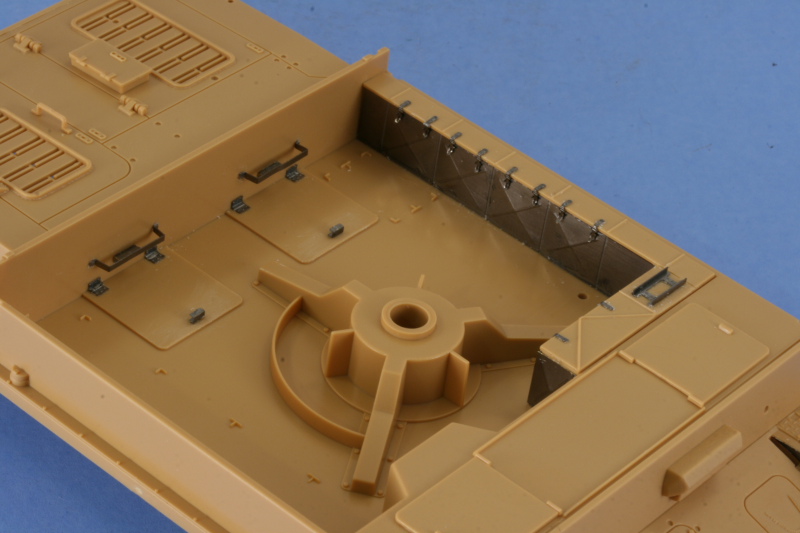
Next up was the interior of the fighting compartment, I removed the simplified molded on handles for the two rear access panels and replaced them with the Eduard parts. The Eduard set included additional detail for this area including the hatch hinges and retaining clips and handles, so these were added as well.
The side ammunition bins were also installed and detailed. The top of the bin had a molded-on ladder shaped item, this was removed and replaced with the Eduard part which was bent to shape and glued in place. The ammunition bin faces are molded smooth on the Tamiya parts, so the Eduard PE faces were used to upgrade this area. The reinforced "X" patterns were created using the point of a wooden toothpick and a piece of hard, but flexible, rubber matting to allow the "X" to be embossed on the outer surface. Eduard allows for this with the inner faces having the X pattern already etched and recommend using a ball-point pin to do this but I've found the toothpick provides a more reliable and consistent pattern and used that instead. Each of the bins received 2 latches which were carefully bent to shape using tweezers and a magnifier and installed with Gator Glue to allow for proper positioning.
Rounding things out for the time being, the lower and upper hulls were joined using regular glue to get a good solid bond. Additional details were then added to the hull including the front Bosch light and "d"-shaped flap support, brake housing vents, rear side grab handles, front tow pintles and spare track holder, and the rear antenna mount.

Next up will be the side walls for the fighting compartment, the kit allows for 3 different modes (full transport, AA only, AA and ground) for the plates and I'll have to study that carefully to determine the placement and use of the various Eduard items to create those details.
Since this is a multi-media build and kitbash/combination exercise, the kit instructions steps will not necessarily be followed to the letter. I started with the lower hull and suspension first, installing the bogies, bump stops and final drive housings as called for in Steps 1 and 3 but left off the return rollers for the time being.
The rear hull plate had it's various elements installed and I used the Eduard PE items to replace the fuel filler cap since it included the retaining chain. The chain was given a 3-D look by carefully bending the flat links 90 degrees to each other using two pairs of tweezers and working one link at a time. PE mounts for the base of the exhaust covers were also added and the rear plate installed to the lower hull.
Next came the road wheels, return rollers, sprockets, and idlers. The kit provides the option for both the earlier welded-tube style and the later cast style idler, I opted for the later style. The sprockets include a polycap insert that will allow them to rotate freely while the idlers do not. The steel return rollers were assembled but not installed since a dry-fit shows they've got a little bit of play to their mounts and I want them to be lined up properly with the rest of the running gear, so they will get installed later on. All of the road wheel halves were removed from the sprues and sanded to remove a slight seam on the rubber portion and the outer halves received their hub caps.
Turning to the upper hull, the side air intakes were added along with the rear fenders, mud flaps, and rear deck plate. The rear deck plate required two molded-on areas originally used on earlier Pz IVs to mount tow cables to be removed, this was done using a #11 blade and carefully sanded down to match the rest of the hull.
The kit parts for the intake covers were replaced with the Eduard items and the retaining wing nuts and side hull clips added. I used Gator Glue, an acrylic binder, to mount the plates and the various parts to allow for some work time to position them properly. I also added the bolt strip detail to the top and bottom of the rear hull bracket, using liquid glue to soften the plastic and gently pressed the strip into place with the tip of a wooden toothpick.
The hull front also received some attention with the access hatches added for the driver and radio operator, the front superstructure plate installed, and details added to the front fenders and mud-flaps. The Eduard items were used here along with a short length of solder bent to shape and glued in place with CA gel to complete the Bosch headlight wiring.
Next up was the interior of the fighting compartment, I removed the simplified molded on handles for the two rear access panels and replaced them with the Eduard parts. The Eduard set included additional detail for this area including the hatch hinges and retaining clips and handles, so these were added as well.
The side ammunition bins were also installed and detailed. The top of the bin had a molded-on ladder shaped item, this was removed and replaced with the Eduard part which was bent to shape and glued in place. The ammunition bin faces are molded smooth on the Tamiya parts, so the Eduard PE faces were used to upgrade this area. The reinforced "X" patterns were created using the point of a wooden toothpick and a piece of hard, but flexible, rubber matting to allow the "X" to be embossed on the outer surface. Eduard allows for this with the inner faces having the X pattern already etched and recommend using a ball-point pin to do this but I've found the toothpick provides a more reliable and consistent pattern and used that instead. Each of the bins received 2 latches which were carefully bent to shape using tweezers and a magnifier and installed with Gator Glue to allow for proper positioning.
Rounding things out for the time being, the lower and upper hulls were joined using regular glue to get a good solid bond. Additional details were then added to the hull including the front Bosch light and "d"-shaped flap support, brake housing vents, rear side grab handles, front tow pintles and spare track holder, and the rear antenna mount.
Next up will be the side walls for the fighting compartment, the kit allows for 3 different modes (full transport, AA only, AA and ground) for the plates and I'll have to study that carefully to determine the placement and use of the various Eduard items to create those details.
-
Bill Plunk
- Posts: 1245
- Joined: Wed Sep 28, 2022 10:18 pm
WIP 08-03-2008
I started off the next round of effort by dealing with the rear hull details that I didn't quite get to last weekend. The mufflers were added along with their Eduard PE braces, a bit of a challenge as the braces need to be angled just right and are a square surface mating up to the rounded surface of the exhausts. I glued them first to the rear hull with Gator Glue, let that set up good and tight, then used a pair of tweezers and liquid glue to carefully attach them to the exhausts directly. Also added were the spare tire holders and the PE reflector for the left side mud-flap.

The next area of attention were the walls of the fighting compartment. The Tamiya kit offers three different options for posing these: fully flat, anti-aircraft mode, or transport mode. I decided for the middle-road approach with the anti-aircraft mode and this in turn required some surgery to the Tamiya parts. The Tamiya instructions rightly tell you to remove the molded-on wing nuts on the extension flaps here and I removed the molded on brackets and replaced them with the Eduard items and wing nuts. There were some slight ejector marks on the inner surfaces that also needed attention, these were carefully sanded down to remove them.


The side panels also had some ejector marks that needed to be sanded down, so this was done first before mounting anything. The Tamiya instructions were followed to mount all the various components, the exceptions being the spare barrels and their retaining clips. I used the Eduard clips and carefully removed the molded on clips from the Tamiya parts by cutting away the excess with sprue cutters first then carefully trimming the rest down with a #11 blade. The surface was then lightly sanded to keep the rounded shape and the two barrel ends were drilled out with a pin vise so that they look like barrels and not solid tubes.
The barrels are only dry-fit into the clips for photo purposes, they will be painted and installed later on after the interior has been painted.

Next came the incredibly tricky task of installing all the panel and getting them to play nice with each other. The Tamiya instructions recommend using clear tape for this step and it's not hard to see why. The panels are designed to be fully workable and since I went with the anti-aircraft mode, the only thing holding them together are the little hooks on either side. Instead of using tape, I carefully braced the panels using toothpicks and needle files and just a touch of liquid glue at the corners to get them to stay together and let it dry for some time to insure everything would stay in the desired location. Not hard to see why they nicknamed this thing a "furniture van"!

With the fighting compartment out of the way, I started in on the Lion Roar Flak 37. Once I had the instructions out and started studying them and comparing it to the Tamiya instructions, it's not hard to see where LR got their inspiration. The assembly steps are virtually identical right down to the parts breakdowns but the LR parts do have better detail definition, so I don't feel like it was a waste.
First up was the base installation of the gun parts along with the barrel. I used the Eduard PE part for the barrel splinter shield because it had better detail. I annealed it on the kitchen stove gas burner and used the Tamiya part to curve it to shape before gluing in place. The LR barrel was mounted and I actually had to enlarge slightly the provided mount holes, go figure, for it to fit but nothing serious.

The rest of the gun base was also constructed following the LR directions for their Step 2. I used the Eduard items to replace the crew foot rests as the LR parts were plain with no tread plate detail. The two tiny loops were added using the LR supplied parts for this side with another three added to the opposite side. I took care to construct the base in firing mode vs. travel mode since the LR kit is designed to be the towed version. I also carefully attached the bearing races for the gun elevation so they would remain positionable, something the Tamiya instructions tell you about but the LR ones do not.

The gun was then installed to the mount along with the ammo feed tray in LR Step 3. The weight of the gun and barrel made it immediately apparent that I would have to fix the gun into position before mounting it into the vehicle.

I test fit the gun into the Tamiya mounting point and then ran a small bit of liquid glue into the elevation races to secure the gun at the desired angle. Once that had dried and I could handle it without it shifting, I added the rest of the gun equipment in the form of the ready ammunition rack on the left side for the LR Step 4. This was a very delicate operation to install it properly has it is mounted in a swivel between the two supports, so I had to use gravity and some strategically positioned toothpicks to get it to dry in the correct position.
I also installed the styrene part that the LR kit provides as the mount post for the splinter shield even though it's not called out in the instructions, it's there just like in the Tamiya kit. In an oddly complicated alternative, the LR instructions actually call for using a length of brass rod and two PE parts to form the mount and the brass rod is conveniently provided as part of the set...yet the styrene part will do just fine if you don't want to go that route.

The right side also received quite a bit of attention with the crew seats added along with the gun laying wheels. The gun sight was also constructed and installed and I used a drill bit to deepen the eye piece and to drill out the external face since it was solid. I used the Eduard PE piece for the shell ejector tray since the LR part didn't have any bend lines provided which would've made that a much harder proposition to get it bent to the right shape.

Next up will come the big challenge, constructing the splinter shield and mounting that.
The next area of attention were the walls of the fighting compartment. The Tamiya kit offers three different options for posing these: fully flat, anti-aircraft mode, or transport mode. I decided for the middle-road approach with the anti-aircraft mode and this in turn required some surgery to the Tamiya parts. The Tamiya instructions rightly tell you to remove the molded-on wing nuts on the extension flaps here and I removed the molded on brackets and replaced them with the Eduard items and wing nuts. There were some slight ejector marks on the inner surfaces that also needed attention, these were carefully sanded down to remove them.
The side panels also had some ejector marks that needed to be sanded down, so this was done first before mounting anything. The Tamiya instructions were followed to mount all the various components, the exceptions being the spare barrels and their retaining clips. I used the Eduard clips and carefully removed the molded on clips from the Tamiya parts by cutting away the excess with sprue cutters first then carefully trimming the rest down with a #11 blade. The surface was then lightly sanded to keep the rounded shape and the two barrel ends were drilled out with a pin vise so that they look like barrels and not solid tubes.
The barrels are only dry-fit into the clips for photo purposes, they will be painted and installed later on after the interior has been painted.
Next came the incredibly tricky task of installing all the panel and getting them to play nice with each other. The Tamiya instructions recommend using clear tape for this step and it's not hard to see why. The panels are designed to be fully workable and since I went with the anti-aircraft mode, the only thing holding them together are the little hooks on either side. Instead of using tape, I carefully braced the panels using toothpicks and needle files and just a touch of liquid glue at the corners to get them to stay together and let it dry for some time to insure everything would stay in the desired location. Not hard to see why they nicknamed this thing a "furniture van"!
With the fighting compartment out of the way, I started in on the Lion Roar Flak 37. Once I had the instructions out and started studying them and comparing it to the Tamiya instructions, it's not hard to see where LR got their inspiration. The assembly steps are virtually identical right down to the parts breakdowns but the LR parts do have better detail definition, so I don't feel like it was a waste.
First up was the base installation of the gun parts along with the barrel. I used the Eduard PE part for the barrel splinter shield because it had better detail. I annealed it on the kitchen stove gas burner and used the Tamiya part to curve it to shape before gluing in place. The LR barrel was mounted and I actually had to enlarge slightly the provided mount holes, go figure, for it to fit but nothing serious.
The rest of the gun base was also constructed following the LR directions for their Step 2. I used the Eduard items to replace the crew foot rests as the LR parts were plain with no tread plate detail. The two tiny loops were added using the LR supplied parts for this side with another three added to the opposite side. I took care to construct the base in firing mode vs. travel mode since the LR kit is designed to be the towed version. I also carefully attached the bearing races for the gun elevation so they would remain positionable, something the Tamiya instructions tell you about but the LR ones do not.
The gun was then installed to the mount along with the ammo feed tray in LR Step 3. The weight of the gun and barrel made it immediately apparent that I would have to fix the gun into position before mounting it into the vehicle.
I test fit the gun into the Tamiya mounting point and then ran a small bit of liquid glue into the elevation races to secure the gun at the desired angle. Once that had dried and I could handle it without it shifting, I added the rest of the gun equipment in the form of the ready ammunition rack on the left side for the LR Step 4. This was a very delicate operation to install it properly has it is mounted in a swivel between the two supports, so I had to use gravity and some strategically positioned toothpicks to get it to dry in the correct position.
I also installed the styrene part that the LR kit provides as the mount post for the splinter shield even though it's not called out in the instructions, it's there just like in the Tamiya kit. In an oddly complicated alternative, the LR instructions actually call for using a length of brass rod and two PE parts to form the mount and the brass rod is conveniently provided as part of the set...yet the styrene part will do just fine if you don't want to go that route.
The right side also received quite a bit of attention with the crew seats added along with the gun laying wheels. The gun sight was also constructed and installed and I used a drill bit to deepen the eye piece and to drill out the external face since it was solid. I used the Eduard PE piece for the shell ejector tray since the LR part didn't have any bend lines provided which would've made that a much harder proposition to get it bent to the right shape.
Next up will come the big challenge, constructing the splinter shield and mounting that.
-
Bill Plunk
- Posts: 1245
- Joined: Wed Sep 28, 2022 10:18 pm
WIP 08-10-2008
After much back and forth comparing the pros and cons of the LR and Eduard PE sets for the gun shield, I ultimately decided in favor of the Eduard shield. While both required soldering to assemble, the Eduard set required far less although what was required did involve some very tricky joins to produce the desired result. I also realized that the LR shield was designed with the towed position in mind vs. deployed or on a vehicle and didn't easily allow for things like the small gunner's scope doors to be opened, a big negative for this particular project. I don't do a lot of soldering for the most part, but I keep a Radio Shack variable 20/40w iron handy along with solder, flux, and a "helping hands" set of clamps for when I do need it. After a couple of hours of careful work with the solder and bending the various angles, the shield was ready.

With the exterior completed, next up was adding all the interior side detail. This involved quite a few extra pieces from the Eduard set, all attached using Gator Glue into their various positions. I used one of the locking arms from the Tamiya kit and one from the LR kit as only one of the LR arms was long enough to do the job.

After numerous test fits, I used CA gel to attach the shield to the base of the gun and then installed the doors for the gunner's sight in the open position.

To round things out with the gun, I assembled the LR styrene parts for the spent shell basket and used the LR parts for the mesh as it had a finer pattern vs. what was supplied in the Eduard set. Ironically, these are the only major parts of PE from the LR kit that I ended up using. All of the pieces fit as designed and only the larger rectangular piece needed to be annealed to get it to fit to shape. Annealing something delicate like this takes extra care and I accomplished this by holding it above the flame on my kitchen stove burner so it would heat up but didn't put it directly into the flame. Delicate pieces that heat up too quickly can incinerate, a lesson I've learned the hard way in the past and was sure not to repeat this time around. I used liquid glue and the handle of a paint brush to carefully shape and attach the screens.

With that taken care of, the final task before painting could begin was to install all the various tools and clamps/hardware. I'd left this off until this stage to minimize the amount of handling and potential for breakage. I started first with the hull front, installing the jack, wire cutters, towing clevises, and the axe. Putty was required to fill in the mount holes and careful scraping away of the tread plate pattern to provide a smooth surface for the metal parts to bond to.

The right rear fender also got some attention with the installation of the hex wrench and the idler tensioning wrenches. The tensioning wrenches as originally supplied by Tamiya had no visible means of support or attachment, so the Eduard set helped tremendously here.

To round out the day's activity, I also installed the pry bar for the left fender and the fire extinguisher. The rear engine deck also received the pick axe

Weather permitting, painting should start next week!
With the exterior completed, next up was adding all the interior side detail. This involved quite a few extra pieces from the Eduard set, all attached using Gator Glue into their various positions. I used one of the locking arms from the Tamiya kit and one from the LR kit as only one of the LR arms was long enough to do the job.
After numerous test fits, I used CA gel to attach the shield to the base of the gun and then installed the doors for the gunner's sight in the open position.
To round things out with the gun, I assembled the LR styrene parts for the spent shell basket and used the LR parts for the mesh as it had a finer pattern vs. what was supplied in the Eduard set. Ironically, these are the only major parts of PE from the LR kit that I ended up using. All of the pieces fit as designed and only the larger rectangular piece needed to be annealed to get it to fit to shape. Annealing something delicate like this takes extra care and I accomplished this by holding it above the flame on my kitchen stove burner so it would heat up but didn't put it directly into the flame. Delicate pieces that heat up too quickly can incinerate, a lesson I've learned the hard way in the past and was sure not to repeat this time around. I used liquid glue and the handle of a paint brush to carefully shape and attach the screens.
With that taken care of, the final task before painting could begin was to install all the various tools and clamps/hardware. I'd left this off until this stage to minimize the amount of handling and potential for breakage. I started first with the hull front, installing the jack, wire cutters, towing clevises, and the axe. Putty was required to fill in the mount holes and careful scraping away of the tread plate pattern to provide a smooth surface for the metal parts to bond to.
The right rear fender also got some attention with the installation of the hex wrench and the idler tensioning wrenches. The tensioning wrenches as originally supplied by Tamiya had no visible means of support or attachment, so the Eduard set helped tremendously here.
To round out the day's activity, I also installed the pry bar for the left fender and the fire extinguisher. The rear engine deck also received the pick axe
Weather permitting, painting should start next week!
-
Bill Plunk
- Posts: 1245
- Joined: Wed Sep 28, 2022 10:18 pm
WIP 08-17-2008
This weekend's update is small, relatively speaking, due to the fact that it coincided with my 12th wedding anniversary and, while my wife is very understanding and supportive of the hobby, that only goes so far!
Due to poor weather yesterday I wasn't able to get any painting done until today. While I did get a head-start on the track assembly yesterday, the progress there isn't sufficient enough yet to justify any photos, so this update will be light on pics as well. All paints referenced on Testor's Model Master Enamels.
The day's efforts meant spending a lot of time with the airbrush out in the garage and the first step was to lay down a primer coat of Italian Dark Brown. This helps insure all the bare plastic areas are covered and provides a solid foundation for the base coat. Once that was on and dried, I applied the base coat using a personalized mix of 80/20 Dunkelgelb/Light Gray. This is applied in multiple very thin passes, slowly building it up over the Dark Brown so as to avoid a single heavy wet coat.
Once that was on and dried, I started in with the camo pattern. I used Khaki for the olivegrun stripes first to set the framework of the pattern then applied the red-brown alternating stripes using a 50/50 mix of Leather/Military Brown. I then went back over the pattern using the previous 80/20 dunkelgelb mix to correct over-spray and fine tune the pattern. The final step was to hold the airbrush about 1-2 feet away from the model and then spray a very light overall mist coat of the same dunkelgelb mix to tie everything in together. The gun is still not attached to the vehicle base to allow for the later detailing to be accomplished.

At the same time as all that was going on, I also airbrushed the road wheels. All of the wheels were mounted on wooden toothpicks using small blobs of blue-tack poster putty to keep them in place. The rubber rim portions were sprayed with Flat Black and then a circle template, with the correct diameter holes masked off, used to spray the dunkelgelb hubs.

During the week I'll likely keep plugging away at the tracks and, once they're done, install the road wheels and go from there.
Due to poor weather yesterday I wasn't able to get any painting done until today. While I did get a head-start on the track assembly yesterday, the progress there isn't sufficient enough yet to justify any photos, so this update will be light on pics as well. All paints referenced on Testor's Model Master Enamels.
The day's efforts meant spending a lot of time with the airbrush out in the garage and the first step was to lay down a primer coat of Italian Dark Brown. This helps insure all the bare plastic areas are covered and provides a solid foundation for the base coat. Once that was on and dried, I applied the base coat using a personalized mix of 80/20 Dunkelgelb/Light Gray. This is applied in multiple very thin passes, slowly building it up over the Dark Brown so as to avoid a single heavy wet coat.
Once that was on and dried, I started in with the camo pattern. I used Khaki for the olivegrun stripes first to set the framework of the pattern then applied the red-brown alternating stripes using a 50/50 mix of Leather/Military Brown. I then went back over the pattern using the previous 80/20 dunkelgelb mix to correct over-spray and fine tune the pattern. The final step was to hold the airbrush about 1-2 feet away from the model and then spray a very light overall mist coat of the same dunkelgelb mix to tie everything in together. The gun is still not attached to the vehicle base to allow for the later detailing to be accomplished.
At the same time as all that was going on, I also airbrushed the road wheels. All of the wheels were mounted on wooden toothpicks using small blobs of blue-tack poster putty to keep them in place. The rubber rim portions were sprayed with Flat Black and then a circle template, with the correct diameter holes masked off, used to spray the dunkelgelb hubs.
During the week I'll likely keep plugging away at the tracks and, once they're done, install the road wheels and go from there.
-
Bill Plunk
- Posts: 1245
- Joined: Wed Sep 28, 2022 10:18 pm
WIP 08-23-2008
Normally I post updates on Sundays but since today was a day of working on the details and then the only thing left is the tracks, I figured I'd go ahead and post today.
The first area of attention were the road wheels, these were assembled from their separate halves and installed onto the vehicle and allowed to dry to provide a solid foundation. Next came the various tools and bits of equipment mounted on the hull. These were detailed individually, with the metal surfaces painted first with non-buffing metalizer Gunmetal and then lightly dry-brushed with Steel. Those with wood handles had them painted with my own custom mix of "wood" color followed by an application of burnt umber artist pastels. The handles on the wire cutters were painted with Italian Dark Brown to recreate the bakelite look since they aren't wood like the rest of the tools. The spare wheels were also installed and the exhausts base coated with the same metalizer Gunmetal and then given a light wash of Rust for their finish.
I also created some light scuffing/scratching in the fighting compartment area where the crew would stand to operate the gun by alternating dry-brushing and stippling of some Burnt Umber. This was then toned down and blended back in with dry-brushing and stippling of some Dunkelgelb. Last but not least, the spare barrels were painted with Gunmetal metalizer and very lightly dry-brushed with Steel and fitted into their clamps.


Next in the detail department was the gun itself. The barrel, ammo feed tray, and the ejector tray were given the same treatment as the spare barrels. The gun sight was detailed with Aircraft Interior Black and the spent shell basket installed. I used the three Tamiya kit-supplied ammo clips and painted up two with yellow heads for HE rounds and one with red heads for incendiary shrapnel. The brass casings were painted with non-buffing metalizer Brass and the fuse caps painted with Steel. The tabs on the ammo clips on the real thing are meant to hook into each other to feed the gun but the Tamiya parts don't allow for that, so only 1 clip was loaded into the gun and the other 2 were set on the ready tray.

I've already started in on 1 of the MK track runs, got about a dozen links assembled before deciding to call it a day. Tomorrow will be a "day of tracks"!
The first area of attention were the road wheels, these were assembled from their separate halves and installed onto the vehicle and allowed to dry to provide a solid foundation. Next came the various tools and bits of equipment mounted on the hull. These were detailed individually, with the metal surfaces painted first with non-buffing metalizer Gunmetal and then lightly dry-brushed with Steel. Those with wood handles had them painted with my own custom mix of "wood" color followed by an application of burnt umber artist pastels. The handles on the wire cutters were painted with Italian Dark Brown to recreate the bakelite look since they aren't wood like the rest of the tools. The spare wheels were also installed and the exhausts base coated with the same metalizer Gunmetal and then given a light wash of Rust for their finish.
I also created some light scuffing/scratching in the fighting compartment area where the crew would stand to operate the gun by alternating dry-brushing and stippling of some Burnt Umber. This was then toned down and blended back in with dry-brushing and stippling of some Dunkelgelb. Last but not least, the spare barrels were painted with Gunmetal metalizer and very lightly dry-brushed with Steel and fitted into their clamps.
Next in the detail department was the gun itself. The barrel, ammo feed tray, and the ejector tray were given the same treatment as the spare barrels. The gun sight was detailed with Aircraft Interior Black and the spent shell basket installed. I used the three Tamiya kit-supplied ammo clips and painted up two with yellow heads for HE rounds and one with red heads for incendiary shrapnel. The brass casings were painted with non-buffing metalizer Brass and the fuse caps painted with Steel. The tabs on the ammo clips on the real thing are meant to hook into each other to feed the gun but the Tamiya parts don't allow for that, so only 1 clip was loaded into the gun and the other 2 were set on the ready tray.
I've already started in on 1 of the MK track runs, got about a dozen links assembled before deciding to call it a day. Tomorrow will be a "day of tracks"!
-
Bill Plunk
- Posts: 1245
- Joined: Wed Sep 28, 2022 10:18 pm
Completion 08-31-2008
As advertised in the last update, the tracks were the next step and this of course follows the usual pattern with MKs, using the provided jig and assembling the runs by installing the workable pins on either side.

While the MK instructions suggest 97 links per side, this is too short and I ended up using 99 links. Because I wasn't careful enough with the pins to insure they actually did seat all the way in, I had several weak pins resulting in the need to run liquid glue along the entire track run and treat it as if it were static indy links instead. I base painted the runs with Testors Model Master Non-buffing Gunmetal, then dry-brushed Steel to create a metallic look, and applied a thin wash of Raw Umber to finish the look before installation. I also used the spare MK links available for the front hull run and finished them in the same way except for using a wash of Rust in place of Raw Umber and dry brushing additional Burnt Umber for their finish.

With that out of the way, I applied a coat of Future by air brush and applied the decal markings. Instead of the Tamiya decals, I hunted in my spares bin and used some Cartograf markings left over from a previous DML build, the Tiger I Initial. Using the cover photo on Panzerwrecks 6 as an inspiration, I added a 3-digit vehicle number to go with the balkenkreuze. The decals were treated with Walther's Solvaset to snug them down to the hull and then a second sealing coat of Future applied. This was allowed to sit overnight before starting in on the weathering process.

The first step was the application of an overall wash of Raw Umber to all of the upper hull surfaces. I used a round 0 sable brush and worked carefully section by section, adjusting any excess as I went with clean thinner.

Then I applied a dot filter of Raw Sienna to add some earth tones to the weathering and some slight streaking for variation. This was followed by a pin wash of Burnt Umber to further pop out the details.

As a final step, I lightly dry-brushed the lightened Dunkelgelb mix used for the base coat to all the surfaces, blending and fading the camo in the process a bit more.

Next came a wet treatment of Mig Pigments Dark Mud, Europe Dust, and African Earth. The three were mixed together first as powders, then ordinary water added and the mixture applied by a large sable brush to the undersides and running gear. This was allowed to air dry over the course of about 1 hour to get to this stage. The pigments end up a slightly lighter color this way than if applied dry, which is why I mix several colors in together.

After it was dry, I proceeded to remove the excess pigment and adjust the finish. This is accomplished as a two-step process, the first is to use a set of stiff bristled brushes to remove as much of the excess as possible. I wear a dust mask while doing this as the very fine pigment particles go airborne very easily and aren't good for the nose/mouth/sinuses/lungs to be inhaled! Once all the excess is removed, the next step is to use a series of moistened q-tips to tone down and adjust the level of pigments.

Then, as a final step, I dry-brushed some Steel to bring back out the high-points on the track faces and everything was finished.

Finished walk-arounds:


While the MK instructions suggest 97 links per side, this is too short and I ended up using 99 links. Because I wasn't careful enough with the pins to insure they actually did seat all the way in, I had several weak pins resulting in the need to run liquid glue along the entire track run and treat it as if it were static indy links instead. I base painted the runs with Testors Model Master Non-buffing Gunmetal, then dry-brushed Steel to create a metallic look, and applied a thin wash of Raw Umber to finish the look before installation. I also used the spare MK links available for the front hull run and finished them in the same way except for using a wash of Rust in place of Raw Umber and dry brushing additional Burnt Umber for their finish.
With that out of the way, I applied a coat of Future by air brush and applied the decal markings. Instead of the Tamiya decals, I hunted in my spares bin and used some Cartograf markings left over from a previous DML build, the Tiger I Initial. Using the cover photo on Panzerwrecks 6 as an inspiration, I added a 3-digit vehicle number to go with the balkenkreuze. The decals were treated with Walther's Solvaset to snug them down to the hull and then a second sealing coat of Future applied. This was allowed to sit overnight before starting in on the weathering process.
The first step was the application of an overall wash of Raw Umber to all of the upper hull surfaces. I used a round 0 sable brush and worked carefully section by section, adjusting any excess as I went with clean thinner.
Then I applied a dot filter of Raw Sienna to add some earth tones to the weathering and some slight streaking for variation. This was followed by a pin wash of Burnt Umber to further pop out the details.
As a final step, I lightly dry-brushed the lightened Dunkelgelb mix used for the base coat to all the surfaces, blending and fading the camo in the process a bit more.
Next came a wet treatment of Mig Pigments Dark Mud, Europe Dust, and African Earth. The three were mixed together first as powders, then ordinary water added and the mixture applied by a large sable brush to the undersides and running gear. This was allowed to air dry over the course of about 1 hour to get to this stage. The pigments end up a slightly lighter color this way than if applied dry, which is why I mix several colors in together.
After it was dry, I proceeded to remove the excess pigment and adjust the finish. This is accomplished as a two-step process, the first is to use a set of stiff bristled brushes to remove as much of the excess as possible. I wear a dust mask while doing this as the very fine pigment particles go airborne very easily and aren't good for the nose/mouth/sinuses/lungs to be inhaled! Once all the excess is removed, the next step is to use a series of moistened q-tips to tone down and adjust the level of pigments.
Then, as a final step, I dry-brushed some Steel to bring back out the high-points on the track faces and everything was finished.
Finished walk-arounds:
-
Bill Plunk
- Posts: 1245
- Joined: Wed Sep 28, 2022 10:18 pm
Publication November 2008
This build is also featured in the Scale Military Modeler International November 2008 issue on pp 62-64.

