Dragon Pzkpfw IV Ausf. F2(G) DAK (2009)

Bill Plunk
Posts: 1245
Joined: Wed Sep 28, 2022 10:18 pm

Dragon Pzkpfw IV Ausf. F2(G) DAK (2009)

Post by Bill Plunk »

Build log for Dragon kit #6360 Pzkpfw IV F2/G Smart Kit with Bison "Pzkpfw IV in Afrika" decals, Model Kasten SK-18 tracks, and Griffon tool clamps.

Image

There are some "easter eggs" in this and other IV Smart Kits (F1 and G) that DML doesn't mention in their instructions but are on the sprues:

1) when adding the hatches for the driver and RO you see Dragon has molded on the padlock locking point but they don't mention you should add the other half of this to the hull ..these are parts number A57.

2)Dragon has added some half wing nuts (A58)on their sprues but don't tell you add one to each of the panels (E21 and E22) to hold them down on the fenders.

3) When building up the barrel in step 14 or 15 ..On part B40 there is a little square in the front corner ...you should drill a small hole in the middle of that square and add part B47.

Another little quirk on the instructions is it says to make the tow ropes 150 mm long but thats including the end loops as well. If you measure the 150mm as being the cable length only, when you try to add them to their hooks they don't fit.
Bill Plunk
Posts: 1245
Joined: Wed Sep 28, 2022 10:18 pm

WIP 12-29-2008

Post by Bill Plunk »

This particular project is one that's been sitting in the back of my mind for a while now and I recently got the "spark" to bring it to the front burner (how's that for mixing cliches!) after browsing through some recent reference material and reading about the "Tropen" schemes used in N. Afrika. This got me to thinking...the orders are well established and clear (see here for the full description: http://www.afrikakorps.org/ralcolors.htm) regarding the schemes to be used in N. Afrika but I'd always just gone with the flow of one-color 'desert yellow' schemes. The Pz IV F2 presented just the right opportunity for me...I've had the Bison "Pz IV in Afrika" set on hand for a while but never got around to using it and it includes markings for an F2 in service with the 8th Regiment, 15th Panzer Division in 1942. There were 2 "Tropen" schemes ordered, one (RAL 8000/RAL 7008) that ran from March '41 until March '42 and one (RAL 8020/RAL 7027) that ran from March '42 until May '43 when the N. Afrika campaign concluded (this of course overlaps with the introduction of Dunkelgelb in Feb. 1943 but that's another story!). The F2 timing is perfect once again since they started production in March '42, so the Testors has the correct RAL 8020 (Afrika Braun) and RAL 7028 (Afrika Dunkelgrau) available even if the Testors names aren't right, they include the RAL # in the product description and the shades are a close match to online color chips, so I'm set! That will be the scheme I will be using, the RAL 8020 as a base coat and the RAL 7027 in a 1/3 pattern over that when it comes time to painting.

Image

In addition, I will be making some modifications to the kit as I go along based on the inspiration of these two photos of F2s in Afrika found using Google Image search along with the configurations provided in the Bison markings sheet.

Image

Image

And, just to make things interesting...my wife asked me the other day how much time it takes me to do a build project...and I could only guess, so this one will be more "precisely" documented as part of the build log process to include total time per update/session as well as "time to date" in the posts. To be honest, I'm a little curious myself! I won't include time spent "waiting" for things like paint to dry or cure, etc. only actual time building or actively working on this project.

So, with that lengthy introduction...here's the first installment. I began with Step 1 which deals with the road wheels, sprockets and idlers. The sprockets were assembled with their 4 parts x 2 (two halves, hub, and back insert) as were the idlers (2 x 2 parts). The return rollers (8 x 2) first had their mold seams sanded down and then were assembled, and the road wheel halves (32) also had their seams sanded down and their hubs (16) added but left separate to facilitate painting later on. That makes for a total of 76 parts for this first step...and it's as far as I got today.

Image

Total time: 3.25 hours

Total time to date: 3.25 hours
Bill Plunk
Posts: 1245
Joined: Wed Sep 28, 2022 10:18 pm

WIP 12-30-2008

Post by Bill Plunk »

Moving right along, work continued today with Step 2. This step has 2 sub-assemblies which deal with the bow and rear hull plates. The bow plate received the tow bracket mounts and hooks while the rear plate was assembled from 3 parts.

Image

These were then installed along with the front halves of the final drive mount plates to the lower hull.

Image

Step 3 addresses more elements of the suspension and also has 2 sub-assemblies, one for the final drive housings and one for the two-part assembles for the 10 bump stops. The armored housing for the front of the final drive is actually 3 parts that assemble smoothly, just a little bit of sanding required where the top and bottom halves meet on the outer surface.

Image

The rest of the step installs the previous sub-assemblies along with the mounts for the suspension elements and the rear tow hooks. The side fuel filler caps are also installed.

Image

Step 4 addresses the details for the rear hull plate and, you guessed it!, has two sub-assembly steps which deal with the multi-part muffler/exhaust and the idler mounts. The muffler consists of 7 parts and goes together well, the only modification I made was to widen the hollow opening for the exhaust pipe a bit with a drill bit and round needle file.

I also assembled the two-part turret traverse motor exhaust and drilled out it's molded solid exhaust pipe with a #80 micro-drill bit.

Image

One thing I should've paid a bit more attention to was the "handed" nature of the idler mounts...they are designed to only fit one side or the other and when I installed the small angled pieces I didn't check that first and so installed them upside down in the previous photo. That was fixed before installation and the hollow lower hole re-drilled out a bit to repair some of the slight glue damage that resulted.

I installed the main and auxiliary exhausts along with the cooling filler pipe and cap and chose the middle version of the tow pintle as a compromise between the three versions offered.

Image

Step 5 is a fairly simple step, it assembles the glacis plate out of two parts and the option is presented to open up the holes for the spare track run. Photos of F2s show some had it, some didn't...and the two reference photos I'm using split the difference between have/have not so I decided to go ahead and fit it. The track run itself will be fitted later after painting. The brake access hatches had their armored covers added and the hatches installed to complete the step.

Image

Step 6 is a busy step...it essentially installs all of the suspension and running gear. I only installed the suspension elements but left off the road wheels, sprockets, and idlers for later. Since the sprue here is a common one with this kit and the G, make sure you choose the right circular caps by following the call-out in the instructions as the two types are side-by-side and it's easy to clip off the wrong ones if you aren't paying attention.

The glacis plate was also installed in this step to round things out.

Image

Next up will be fitting the fenders and then on to the upper hull!

Total session time: 5.25 hours

Total time to date: 8.50 hours
Bill Plunk
Posts: 1245
Joined: Wed Sep 28, 2022 10:18 pm

WIP 12-31-2008

Post by Bill Plunk »

The final model day of 2008 was a productive one. I continued on with Step 7 which deals with the fenders and their installation onto the hull.

The step directs you to install the front and rear mudflaps first, but experience with the G taught me that it's better to attach the fenders to the hull first before mounting the rear flaps, so they were left off for the moment. I also filled in the mount holes that I won't be using on the different sides, some because tools are going to be relocated and some because the Griffon clamps are going to stand-in. Where the Griffon clamps will be used, I carefully removed some of the raised pattern to provide a level surface for gluing. I also sanded down the section on the left side fender where a 4-can jerry-can rack will go to allow the cans to also sit properly.

Image

With that out of the way, both fenders were installed to the hull and the rear flaps added. The fenders have a tendency to want to bow upward slightly at the front and back, so to counteract that I glued them down solidly in the middle first and then added liquid glue to the rear only to straighten things out. I didn't address the front because that would be dealt with when the hull was added. The bulkhead separating the fighting compartment and the engine bay was also added and some slight finger pressure used on the hull sides to get a squared-up join all around.

Image

Moving on to Step 8/9 (they really are the same thing just one step per side), the superstructure sides received their view ports. These are designed to be left workable if you're really careful with how you glue them in place, which comes in very handy in the later steps when it's time to join them to the superstructure frame. I glued the clear armored blocks into place and masked them with blue tack poster putty. The mount hole for the crew step was opened up but not the holes for the cleaning rods as they are going to be repositioned due to the jerry can rack being located there. The mount hole for the shovel handle was filled with putty and sanded down in anticipation of the Griffon clamp going there later.

Image

Step 10 is a big step with multiple sub-assemblies designed to get everything ready to assemble the superstructure. The side intakes are a two-part assembly with two choices offered, I chose the one with the sunken bolt heads just because. The rear engine deck plate received the hooks for the tow cables and I chose the option of adding the armored smoke candle box as well. The engine deck access hatches received some details although I didn't use the PE slats for the underside since they make sense only if you want to model the slats closed. The front superstructure plate was also assembled with the driver's visor and armored glass installed and the glass masked with blue tack. On the ball MG mount, I cheated a bit and only used the one part for the barrel as there's no point in assembling the full thing if the radio operator's hatch isn't going to be open.

Image

Step 11 brings everything together to form the superstructure and then installs the superstructure to the hull. I added the sides first along with the air intakes, using liquid glue to get a seamless join with the molded-on weld seams. This takes a little patience and careful application of pressure but DML's positioning of the weld seams makes this a neat extra detail IMHO. Once that had set, the front plate came next, again using strategic finger pressure for its join. The rear plate was last. It was here that leaving the view ports workable paid off...I could close them while working with these areas and be able to apply pressure where needed knowing they could just open right back up again after I was done.

Image


To complete the step, the superstructure was mated with the lower hull. I used a combination of regular glue and liquid glue on the different surfaces for the initial joins. Finger pressure was needed at certain points with the fenders to get them to mate solid as well as at the rear hull plate, but nothing too out of the ordinary. The fit overall is nice and tight. I will have to fill the two open holes on the left side air intake since the cleaning rods there are going to be relocated as well, but will deal with that after the hull has set up thoroughly.

I also decided to keep only the driver's side view port in the open position. The radio operator's view port doesn't have much clearance with the lifting hook, so it would barely be open to begin with so it's not really worth the trouble. I also will be adding some spare track armor there and next to the hull MG, so it made sense in the long run to close it up.

Image

Hope everyone has a safe New Year's Eve and wish you a Happy New Year!

Total session time: 5 hours

Total time to date: 13.5 hours
Bill Plunk
Posts: 1245
Joined: Wed Sep 28, 2022 10:18 pm

WIP 01-01-2009

Post by Bill Plunk »

With the hull thoroughly joined, I started in on the fender and side details. The front hull received the lower portion of the spare track holder that I'd left off deliberately in Step 7, the upper portion will get added once the spare track run is installed. I added the Notek light to the left fender and provided the missing wiring conduit in the form of some .022" solder bent to shape and glued in place.

Image

Step 12 deals with all the various tools and details that need to be added to the left side. I will be leaving all of the tools off until after painting so they weren't installed just yet. The holes in the left intake were filled with putty and sanded down and the crew step installed. Some F2s had the step, some didn't but I elected to include it. This limited the amount of space available for the jerry can rack to only allow for 3 cans, but that's fine for my purposes.

The field-mod rack was scratch-built from excess material from an Eduard PE fret. I cut out a single long strip and used the Dremel to remove any bumps/stubs. The strip was deliberately longer than I needed and to fit 3 cans, the rack needed to measure 16mm long and 6 mm deep. This was accomplished by bending the strip using my Ausfwerks Fender Bender metal brake and cutting done the excess with side cutters. It was then glued in place with Gator Grip glue so I could get it positioned straight and level and allowed to set up.

The Griffon clamp for the long pry-bar was installed and the kit-supplied PE used for the fender support and the air intake flaps. The kit provides styrene options if you don't want to go the PE route but in both cases I felt the PE offered more in-scale detail so opted for them.

The instructions in Step 12 contain an omission, they show part B22 (the grab handle above the crew step) as installed but it's never called out as a part. This same error was carried over into the G kit instructions so I was aware of it beforehand and knew where to look on the sprues.

Image

In order to save time at this point, I went ahead and cleaned up all the left side tools even though they won't be installed just yet. The long pry-bar had it's molded on clamp removed and the tensioning wrench had its tapered end sanded down as it is molded too thick and uniform. I also removed the mount pins from the wrench and the gun cleaning rods as they will be mounted ultimately in places with no holes.

Image

Using the very highly detailed jerry-can set from a previous DML Pz I-B project, I assembled three cans complete with PE inserts and marked as 20L Wasser cans.

Image

These were then test-fit into the rack and all my measurements paid off with a snug fit.

Image

Total session time: 3.5 hours

Total time to date: 17 hours

Next up is the right side fender and then on to the turret!
Bill Plunk
Posts: 1245
Joined: Wed Sep 28, 2022 10:18 pm

WIP 01-02-2009

Post by Bill Plunk »

Lots of work was completed today so I'll dive right in...beginning first with the right side fender and Step 13, it received similar treatment as the left side yesterday. The intake flaps were installed along with the antenna tray and antenna, the PE fender support bracket, etc. All of the tools were left off with the exception of the track changing tool, this needed to be installed because of the overlap with the front fender support bracket...experience with the G taught me this one can't be fitted later on if the bracket is already in place, so on it goes. The Griffon clamps for the short pry-bar, the shovel, the crank starter, and the axe were also installed.

Image

All of the tools that were left off had their molded on clamps carefully removed and their handles sanded down where appropriate. I assembled the multi-part jack but left the brackets off for now for easier painting. Because of where the jack installs, I'm going to save it for later as I have plans for some extra track links on that side of the hull and need access to it.

Image

The three individual links that install on this fender also got some attention. They are molded solid but without the linking pins, so I used a pin vise and micro drill bit to open the holes up. There were also two small ejector pin marks on the top portion of their clamps that had to be carefully removed.

Image

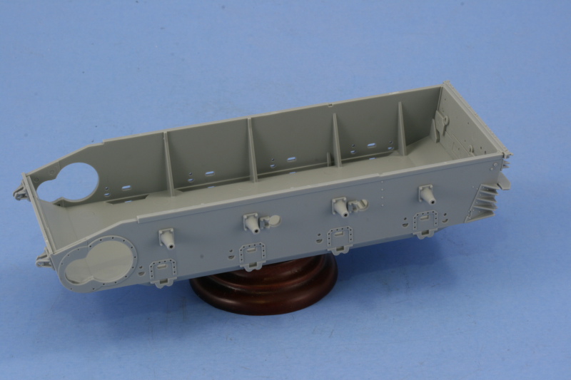
To round things out with the lower hull, I scratch-built two spare wheel holders from 24-gauge steel wire. I used blue tack to hold a wheel together as a template as a temporary solution, bent the wire to shape, then adjusted until I had the spacing right...it took 3 attempts before I got it down, but was worth it. Once I had one the right shape, making the second one was a piece of cake. The wire was mounted using CA gel so it could support the weight. I had considered using solder but didn't think it would keep its shape over time so went with the sturdier steel wire just to be sure.

Image

Image

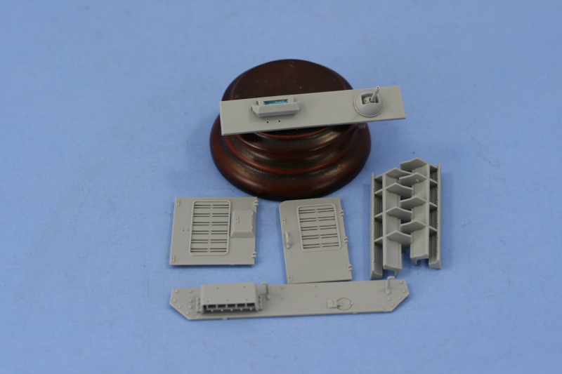
Step 14 begins work on the turret by focusing first on the main gun. The mantle is constructed from 5 parts and the option is given to fit the sleeve 2 different ways, changing the placement of the screws in the process. I didn't really pick one over the other as the photos I'm using aren't clear enough to say one way or the other. This step also provides the option of installing the coaxial MG sleeve with the barrel present or not...a handy thing if you wanted to show the coaxial MG missing (ad hoc AA mount, wreck that's been picked over, etc.), I of course chose it with the MG in place.

Image

Step 15 assembles the rest of the main gun by adding the barrel, the recoil housing, the mount into the turret, and the muzzle brake. This step also calls for the installation of the mount swivel points, parts B11 and B12, but I left them off because if you install them later, the gun will be movable if you're careful with the glue and don't attach them to the pins on B34...something Step 15 doesn't point out. The muzzle brake is two parts but use of liquid glue and careful sanding will create a seamless look. The slight seam on the one-piece barrel was also carefully sanded down to complete things here.

Image

Step 16 installs the gun into the front turret plate and adds the breech and recoil guards. There are two sub-steps, one calls for the front turret plate to have the two view ports added, I elected to pose the gunner's in the open position. The other calls for the assembly of the breech and breech block.

Image

The gun was installed into the turret front plate first and then the breech and recoil guards added to complete the step.

Image

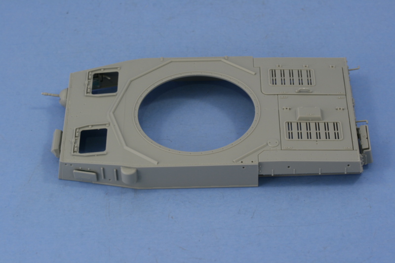
Step 17 is a collection of sub-steps dealing with the turret and turret accessories. The first is a busy one dealing with the turret interior. Both the side vision ports are installed and can be made workable if careful with the glue. I plan to leave the gunner's side open when the build is finished but for now it's in the closed position. The inner frames for the turret side hatches, parts G18, should also install in this step and they are shown in place on the diagram but they aren't called out by parts number or arrows, so this is a potential pitfall. If the frames aren't installed, it makes it much more difficult to get the side hatch hinges and outer doors in the correct position.

This little sub-step also adds the rear turret pistol ports and the lifting eyes. It directs you to install the exhaust fan but I left this off until the next step as it needs to integrate with some of the top parts and that's difficult to do at this point since they aren't installed yet.

Image

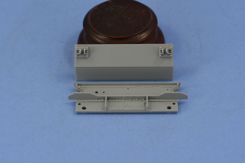
The other sub-steps deal with the rear turret stowage box and the commander's cupola. The cupola is a multi-part assembly with options to pose the armored shutters in the open or closed position. Since these were operated independently, I elected to open only the front facing port and left all the others in the closed position. The hatches were installed in the closed position and are a very tight fit with the hinge points so be careful here or you can damage the pins.

Image

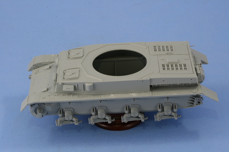
Step 18 is the moment of truth...it assembles all the previous sub-assemblies to construct the turret and add its remaining details. To construct the turret you must first add the main gun and front plate to the top, then add the turret bottom. If you add the bottom first, the gun breech won't fit in the gap available, so the order of things is important here. I used a combination of regular glue, liquid glue, and strategic finger pressure to get all the weld seams to join and seal up properly.

Once dry, the details were added. I removed the molded on base of the commander's sighting vane and used the kit-provided PE replacement and installed the ventilator cover and signal port flap. The side hatches were assembled and installed and while the diagram is a bit confusing and has a couple of the hinge parts swapped around in the numbering, so long as the inner bases were installed in the previous step you can't install things wrong. The inner bases have two different sized "D" shaped pins that correspond to the correct hinge parts and so long as you have the pistol port door as the rearmost door on either side, everything goes in just fine. The instructions have an error in the parts number for the rain gutters, these are not A39 as labelled but are actually A37.

Last but not least, the cupola and storage box were installed.

Image

And, just to stay in the spirit of things, Step 19 calls for the turret to be fitted to the lower hull.

Image

Things are now ready to move to the painting stage.

Total session time: 8.25 hours

Total time to date: 25.25 hours
Bill Plunk
Posts: 1245
Joined: Wed Sep 28, 2022 10:18 pm

WIP 01-03-2009

Post by Bill Plunk »

Today's efforts focused exclusively on painting. I had very good weather (shirt sleeves) so took full advantage of it with a marathon session with the airbrush...even running out of daylight at one point and having to haul out a desk lamp to the garage to finish up!

The initial prep work involved mostly getting the road wheels ready, all 40 of them, by mounting them on wooden toothpicks using blue tack and a couple of night crawler styrofoam boxes that I keep around for that purpose. The turret was also mounted on a handle in the form of a cut-down cardboard tube with a strip of blue painter's tape attached to the top to make it easier to manipulate it during painting. The turret ring is just the right diameter for this so long as the commander's seat isn't mounted...and since I wasn't displaying the interior, that was left off in the build steps deliberately.

Image

All the paints referenced are Model Master II enamels. I began by applying a primer coat of Italian Dark Brown. I used this color because it provides a nice contrast to the light gray plastic to insure there aren't any unpainted areas, it allows for a check of sanding and putty work before committing to the base coat, it applies nice and smooth, and also is a good underlying color for both lighter and darker colors. Enamels have a tendency to "sink in" to one another as they cure, so it also provides a good foundation in that regard.

Image

The base coat of Afrika Braun (RAL 8020 despite the name) was applied in thin multiple passes over the primer coat to slowly build it up and get even coverage.

Image

While that was drying, I also worked on the 40 road wheels, the return rollers, idlers, and sprockets. The rubber portions were first sprayed with Gunmetal as a nice slightly grayish "black" color and allowed to dry. Then, using a draftsman's circle template, I sprayed the hubs with the Afrika Braun. Since there were 40 wheel halves (32 for the suspension, 8 for the spares), this had to be done 80 times (both front and back) so even with the template this took a little bit of time to accomplish. Without the template it would've taken much longer.

Image

Next the camo pattern was applied to the hull and turret using Afrika Dunkelgrau (RAL 7027 despite the name). I thinned this appropriately and dropped the pressure down to around 15 psi and worked very close in to the vehicle surface. Due to the relatively low contrast between the two colors, it was slow going (and why I needed the added light in the garage!) but eventually I got the pattern in the way I wanted it.

Image

Total session time: 6.5 hours

Total time to date: 31.75 hours

Next up will be installing the wheels and working on the details, then it's on to the tracks.
Bill Plunk
Posts: 1245
Joined: Wed Sep 28, 2022 10:18 pm

WIP 01-04-2009

Post by Bill Plunk »

Today's efforts were all about the details...which means there aren't a whole lot of photos in this update even though quite a bit was accomplished. First up were the assembly of all the painted road wheels and their installation along with the return rollers. This was then set off to the side in a safe place to allow the wheels to thoroughly set up before further handling.

Image

I had plenty to keep me occupied in the form of all the gear for the fenders that had been left off up until now. All of them were detail painted with the metal surfaces finished with Non-Buffing Metalizer Gunmetal followed by a light dry-brushing of Steel. The wood handles were painted with my own special mix of "wood" color then given a light wash of Leather followed by a dusting of burnt umber artist pastels. Those tools with molded on clamps had them painted to match the camo pattern where appropriate. Just to add a little variety, I finished the fire extinguisher in Panzer Gray as a "replacement" item vs. the original equipment. The 3 water cans for the side were also painted in Panzer Gray and their water crosses added using Light Gray. I masked the crosses one bar at a time with blue masking tape and sprayed Light Gray with the airbrush. The cans were then given a little wear-and-tear in the form of some dry-brushed Steel around their edges and handles as well as the pour spouts. The three spare links were painted the same as the metal tool heads but given an additional light wash of Rust. I also added some detail to the jack block by lightly scoring the surface using my light magnifier and the tip of a #11 blade to create some wood-grain detail before it was given the Leather wash and artist pastel treatment.

Image

Once all the detail work was done, it was time to mount them. I started with the left side fender and worked front-to-back. Once everything was in place, I added the spare wheel into its mount using CA gel in the "saddle" curve so it would stay put during future handling. Since the jerry can rack took up the space normally occupied by the tensioning wrench, it had to go somewhere...and if you look back at the reference photos I posted in the first entry, you'll see where the enterprising crew stuck it...on the lower hull above the third suspension bogie and just under the fuel filler caps, so that's where mine went too! I also had to find a home for the gun cleaning rods and the only available space was on the rear engine deck and the sponge end needed to face the rear to avoid fouling the turret stowage bin...this is a bit of guess-work on my part as the crew wouldn't discard this item and the spare wheel racks make it impossible for them to go in their original spot. The smaller two rods were put in the same spot over on the right side for the same reason.

Image

The right side gear was also installed and this side is a bit more crowded. The fit of the shovel, the three spare links, and the jack are all very tight with little margin for error. As a result I installed the shovel first, then the spare links, then the jack to get everything in the right spot.

Image

I had also started in on the rear hull details and done a bit of work with the hull and coaxial MGs but ran out of time to complete those areas.

Not bad for the last day of a very enjoyable vacation! Unfortunately that also means that work on this will go back to a normal schedule of mainly weekends, so this will be the last of the "daily" reports that I've been filing since starting.

Total session time: 6.5 hours

Total time to date: 38.25 hours
Bill Plunk
Posts: 1245
Joined: Wed Sep 28, 2022 10:18 pm

WIP 01-10-2009

Post by Bill Plunk »

With most of the hull details complete, I turned to the tracks as the next big area needing time and attention. The Model Kasten tracks assemble as individual links with separate pins and separate hollow guide horns using a provided jig for 8 links at a time. The SK-18 set includes 212 links and recommends 99-100 links for a Pz IV. Over the course of several days 1-2 hours at time while watching TV as a background distraction, I assembled the left and right runs. Test fits showed that I needed 100 links for the left side and 99 for the right to get the amount of sag and idler position I wanted...why is it different? Simple...the links aren't exactly identical although they appear that way to the eye and once assembled sometimes have a little give to them and sometimes not...the right side simply had a tiny bit more give to them so didn't need the 100th link! One set of MK's wasn't enough though for what I wanted to do with this build as I needed 20 links for the turret roof and another 7 for the superstructure front, so I used some left over spares from previous projects along with the 13

Image

All told it took about 9.5 hours to assemble both track runs and do the test-fits...but it's worth it IMHO. Not only are the tracks workable and provide the additional flexibility in painting and finishing that represents but they also have superior detail to the DML "Magic" indy links. The MK links have a more accurate guide-horn and better detail with the little hollow side extensions as well and while the "magic" links aren't on sprues, they still require cleanup in terms of removing two raised pin marks per link and dealing with a slight scar on the guide horn. The MKs still take more time to assemble, but have a bigger payoff in the end.

Image

Back to the front hull, I assembled the spare track run using the special DML provided parts that include the link pins already in place on the front and rear links and the mount pins for the glacis. This is a 7-link run so 4 links from the Magic set are needed to fill in the gaps, so these were cleaned up and added. The run was positioned on the glacis to allow it to dry in place and aligned but hasn't yet been glued down permanently with the holders as I need to paint the run first as well as the holders, so more work to be done there.

The 10-link spare run was constructed with 10 of the Magic links and dry-fit to allow it to also dry straight. I also decided to add the bowed out run often seen on DAK vehicles as an ad-hoc way to carry additional gear between the two hooks. This was constructed from 17 Magic links and the tow pins inserted to secure the front and back and the two spare wheels used to shape the bow correctly. I accidentally broke off the handle on one of the pins but recovered it from the floor, so it will be repaired a bit later on. This run is removable and will be painted and weathered and permanently installed prior to the weathering stages.

Last but not least, I discovered after looking at several pics of F1s that the spare links carried on the superstructure front were commonly secured with welded on bars instead of welded directly to the plate, so this meant I needed to add those. I used scrap PE from an old Eduard Fret and formed the holders with pliers and tweezers before gluing in place with Gator Grip glue to avoid marring the paint work.

Image

The spare tracks were then test-fit to the superstructure front along with the 20-link run for the turret. I discovered that I needed to remove the side lifting hooks to allow the turret strip to fit properly and will have to be a bit creative with the gluing to get them to lay flat properly due to the travel limitation on the MK pins. For now, it's dry-fit to the roof but tests with finger pressure show they will easily lay down on the turret sides with just a little coaxing. I need to apply the turret decals first before adding this as the track will overlap it, so this will get installed after that has been accomplished.

Image

I'll be breaking out the AB tomorrow to paint the track runs and touch up a couple of spots here and there on the camo scheme and then it will be decal time!

Total Session time: 14.75 hours

Total Time to Date: 53.00 hours
Bill Plunk
Posts: 1245
Joined: Wed Sep 28, 2022 10:18 pm

WIP 01-11-2009

Post by Bill Plunk »

I thought I would get all the way through to the decals today but the little details remaining consumed more time than I had anticipated...so while progress was made, it just wasn't as far as I'd hoped.

I spent a good bit of time wrestling with the tow cables on the rear hull without success. The wire DML provides is very stiff and springy, so I tried annealing it over the gas flame on the stove and while that helped a little, it wasn't enough. I managed to snap off the plastic supports while fiddling around and so ended up replacing them with bent brass rod instead...and may try one more time on the tow cable with these stronger supports...we'll see. The exhaust was finished up with some washes of Rust and dry brushed Burnt Umber and the Notek lenses painted with Tamiya Clear Green and the reflector with Clear Red.

Image

As you can see, both of the tracks have also been installed. These were base coated first with Flat Black then sprayed with Non-Buffing Metalizer Gunmetal. Once dry, they were dry-brushed with Steel and an overall wash of Raw Umber applied and then set off to the side. The sprocket teeth and contact surfaces on the idler were dry brushed with Steel and the lower hull received some slight scuffs and nicks with dry brushed Burnt Umber. The sprocket and idler were then glued into position and the tracks installed on both sides.

Image

The spare tracks were also all painted and detailed the same as the running tracks except they were given a wash of Burnt Umber. These were all carefully positioned and then glued into place with the exception of the turret strip.

Image

The season premiere of "24" called a halt to the day's activities so the markings will have to wait a bit as a result.

Total Session Time: 5 hours
Total Time To Date 58 hours
Post Reply