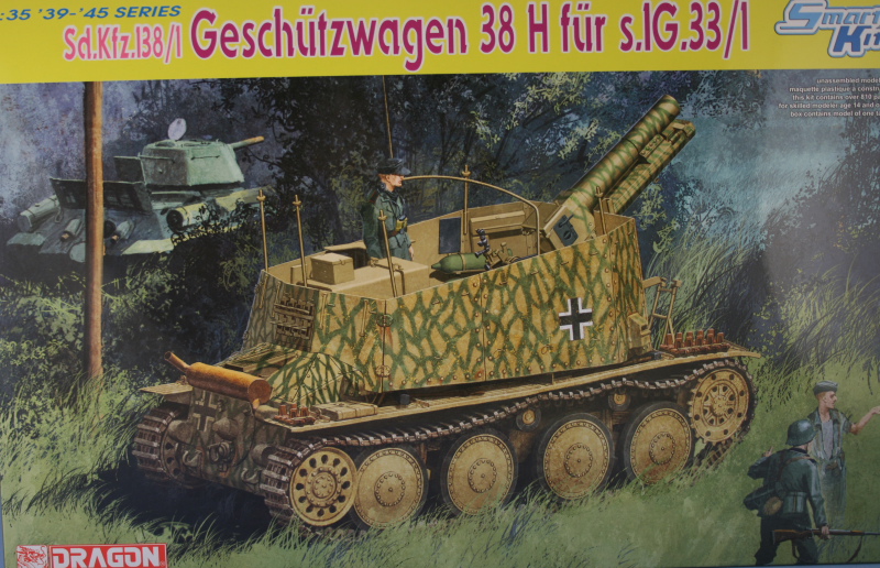
Dragon Sdkfz 138/1 Geschutzwagen 38 H fur sIG 33/1 (Grille H) (2009)
-
Bill Plunk
- Posts: 1245
- Joined: Wed Sep 28, 2022 10:18 pm
Dragon Sdkfz 138/1 Geschutzwagen 38 H fur sIG 33/1 (Grille H) (2009)
Build log for Dragon kit #6470 Sdkfz 138/1 Geschutzwagen 38 h fur sIG 33/1 Smart Kit or Grille H as an OOB project.
-
Bill Plunk
- Posts: 1245
- Joined: Wed Sep 28, 2022 10:18 pm
WIP 03-19-2009
I had this all written up last night but got distracted and so didn't get around to posting it. Work started on this in the evening since there wasn't anything particularly good on TV, and began where it normally does with Step 1 dealing with the sprockets, idlers, and road wheels.
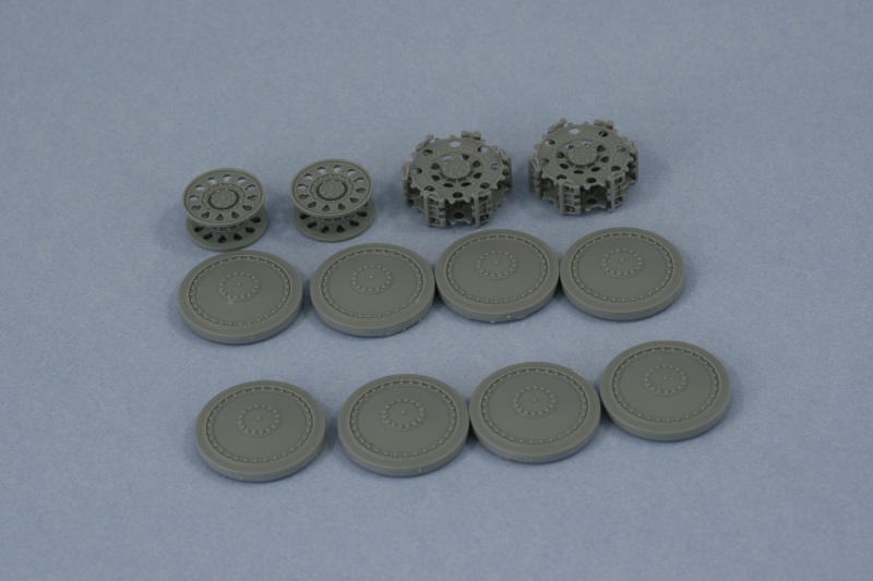
Each road wheel was removed from the sprue and has 4 connection points and a largish seam that needed to be sanded down. I used a flexible sanding board to accomplish this, one wheel at a time. The step instructions appear to give you an option of using two different types of sprockets and idlers but only one type is really correct for the Grille H. That's the "early" type that have holes in the sprockets (parts A3/A4) and the tear-drop shaped holes in the idlers (A5/A6). The sprockets in particular have difficult sprue attachment points, some so close to the guide teeth that they are almost integrated, so I cut them away from the sprue with enough of the stub remaining to allow their removal with a sharp knife vs. using sprue cutters for that job.
The sprockets are a two-part assembly with a small locating tab designed to help insure correct alignment but the tab is smaller than the socket so there's a little bit of play there. This can cause the sprocket teeth to not align properly which of course will cause problems when fitting the tracks, so I used 6 links of loose Magic tracks to insure that the sprockets were properly "gapped" to allow clearance of the link guide horns as well as proper fit and alignment of the teeth into the links. The track links were evenly spaced around the sprocket and left in place as the glue dried. The idlers also use interlocking tabs, 2 instead of 1 like the sprockets, but these are also loose so care is needed to insure they too are properly aligned when installing.
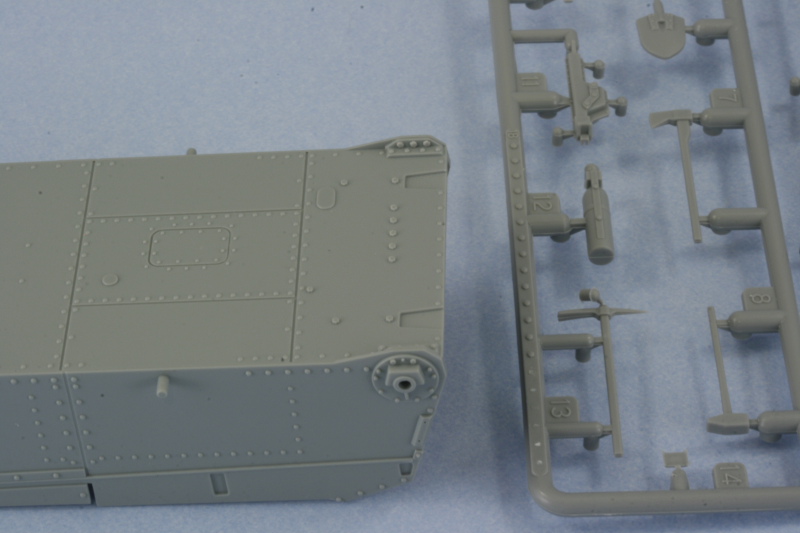
The next little item was the addition of 3 bolt heads to the lower hull brace for the idler mount. The bolt heads come on sprue K and have to be carefully sliced off and then glued into position on the lower hull. Not something that will be readily seen on the finished build unless you flip it over, but it's there for the curious.
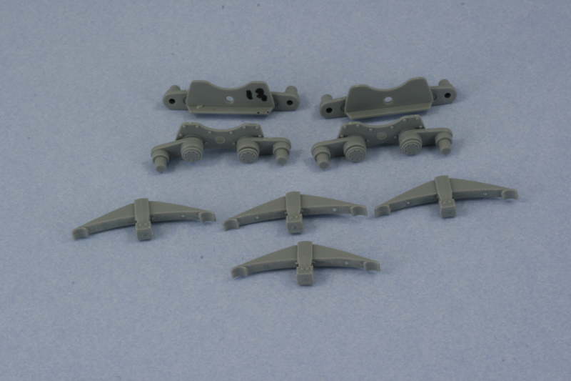
Continuing on with the suspension, the sub-assembly step that constructs the bogey mounts was assembled. The diagram here is a bit misleading...it seems to indicate that you can add the springs to the hull mount plate but that actually isn't possible until Step 6 because the post that the spring would attach to is molded onto the lower hull. The little gray arrow that points to the hole in the plate is marked as not to be glued...which doubles the irony because there's nothing to glue it to anyway! You are presented with the option of using either springs with the open slotted cover or the solid cover, the solid cover is the correct type as the slotted covers were used primarily on the early gun-tank versions while the solid cover was a later style. For those interested in super accuracy, both spring types feature 15 springs when the slotted cover type should only have 14 per the descriptions in Panzer Tracts No. 18. I attached the swing arms to both plates and carefully glued in the caps so that the arms would remain movable. This will help insure the road wheels sit level later on when they are installed. Since Step 6 is a long way off, I used a permanent marker to mark the two A13 plates since the instructions indicate it's important which set goes on which side.
Total session time: 2.5 hours
Total time to date: 2.5 hours
Each road wheel was removed from the sprue and has 4 connection points and a largish seam that needed to be sanded down. I used a flexible sanding board to accomplish this, one wheel at a time. The step instructions appear to give you an option of using two different types of sprockets and idlers but only one type is really correct for the Grille H. That's the "early" type that have holes in the sprockets (parts A3/A4) and the tear-drop shaped holes in the idlers (A5/A6). The sprockets in particular have difficult sprue attachment points, some so close to the guide teeth that they are almost integrated, so I cut them away from the sprue with enough of the stub remaining to allow their removal with a sharp knife vs. using sprue cutters for that job.
The sprockets are a two-part assembly with a small locating tab designed to help insure correct alignment but the tab is smaller than the socket so there's a little bit of play there. This can cause the sprocket teeth to not align properly which of course will cause problems when fitting the tracks, so I used 6 links of loose Magic tracks to insure that the sprockets were properly "gapped" to allow clearance of the link guide horns as well as proper fit and alignment of the teeth into the links. The track links were evenly spaced around the sprocket and left in place as the glue dried. The idlers also use interlocking tabs, 2 instead of 1 like the sprockets, but these are also loose so care is needed to insure they too are properly aligned when installing.
The next little item was the addition of 3 bolt heads to the lower hull brace for the idler mount. The bolt heads come on sprue K and have to be carefully sliced off and then glued into position on the lower hull. Not something that will be readily seen on the finished build unless you flip it over, but it's there for the curious.
Continuing on with the suspension, the sub-assembly step that constructs the bogey mounts was assembled. The diagram here is a bit misleading...it seems to indicate that you can add the springs to the hull mount plate but that actually isn't possible until Step 6 because the post that the spring would attach to is molded onto the lower hull. The little gray arrow that points to the hole in the plate is marked as not to be glued...which doubles the irony because there's nothing to glue it to anyway! You are presented with the option of using either springs with the open slotted cover or the solid cover, the solid cover is the correct type as the slotted covers were used primarily on the early gun-tank versions while the solid cover was a later style. For those interested in super accuracy, both spring types feature 15 springs when the slotted cover type should only have 14 per the descriptions in Panzer Tracts No. 18. I attached the swing arms to both plates and carefully glued in the caps so that the arms would remain movable. This will help insure the road wheels sit level later on when they are installed. Since Step 6 is a long way off, I used a permanent marker to mark the two A13 plates since the instructions indicate it's important which set goes on which side.
Total session time: 2.5 hours
Total time to date: 2.5 hours
-
Bill Plunk
- Posts: 1245
- Joined: Wed Sep 28, 2022 10:18 pm
WIP 03-21-2009
Made a lot of progress today on the little stuff...since this is an open topped vehicle and the interior will be largely visible, I focused on that and skipped around in the steps as a result.
First up was the completion of the items in Step 2. This installs the return roller mounts and final drive housings to the exterior. It also calls for the installation of the idler mounts but I'm leaving that off until later to allow for more flexibility when the time comes to mount the tracks and get the proper position/tension. This step also calls for the installation of the ends of the final drive shafts, something that after I had installed them I think would've been better to wait on due to the way the brake housing and actual shafts install into them, more on that in just a bit.
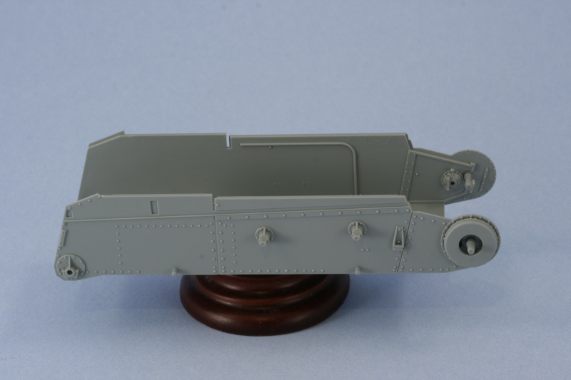
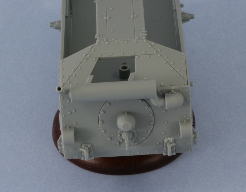
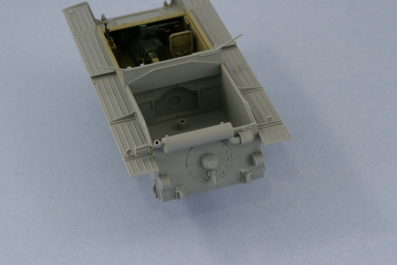
Step 3 deals with the assembly of the rear hull plate details but since the plate itself doesn't get installed to the hull until Step 5, I decided to rearrange things a bit and installed the plate first, then added the details. This proved to be a wise approach especially in regards to the muffler mounts as they have a very small surface area to mount to and it's best done on a stable platform.
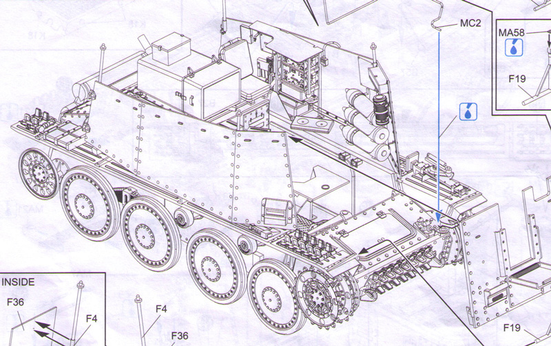
The muffler assembly requires a modification to the exhaust pipe to allow it to be positioned at the correct angle instead of vertical and the instructions point out that the pipe needs the tab cut away to do this, easily done with sprue cutters and cleaned up with a #11 knife. The instructions include a helpful diagram to get the pipe aligned at the correct angle and the easiest way to achieve this is to glue the pipe into the muffler then use the diagram like you would any line drawing and rotate it to match the angle. I also enlarged the hole in the pipe with the point of #11 knife as it appeared too small for my liking. The seam from the two part assembly was sanded down and a test fit of the pipe that enters the hull showed the hole in the hull was too small...so I used a round needle file to enlarge it to the right diameter. The armored cover also required some adjustment with the needle file to have sufficient clearance to mount flush to the hull.
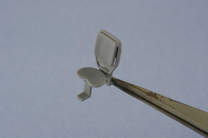
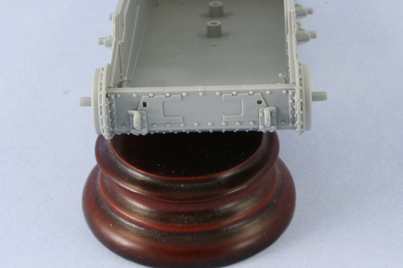
The rest of the details were added, the step gives you the option of armored or unarmored idler covers but only the armored are appropriate. An option is provided for the tow hitch and I chose the one with the rectangular latch vs. the open hook based on reference photos. The armored cover was added to the round transmission hatch and the rear tow hooks installed. Some putty was required to fill gaps on the molded in slots, more on the bottom than on the top. The tow hooks also had to have their tabs trimmed down as they were too large to fit the cutouts provided.
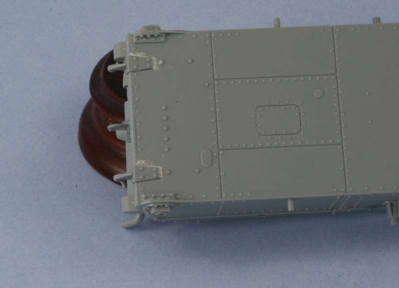
Step 4 deals with the fenders and I skipped that for now but will come back to it shortly. Step 5 calls for the installation of the rear hull plate (already done) and the fenders, so it too was skipped. It's important to note that this step shows the driver's knee pad already installed on the right hull side but doesn't have a part number assigned to it. It's A17 and I will paint and install that separately. This is an error/oversight on DML's part in the instructions and is an easy one to miss if you aren't paying attention.
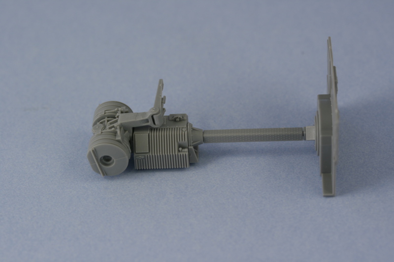
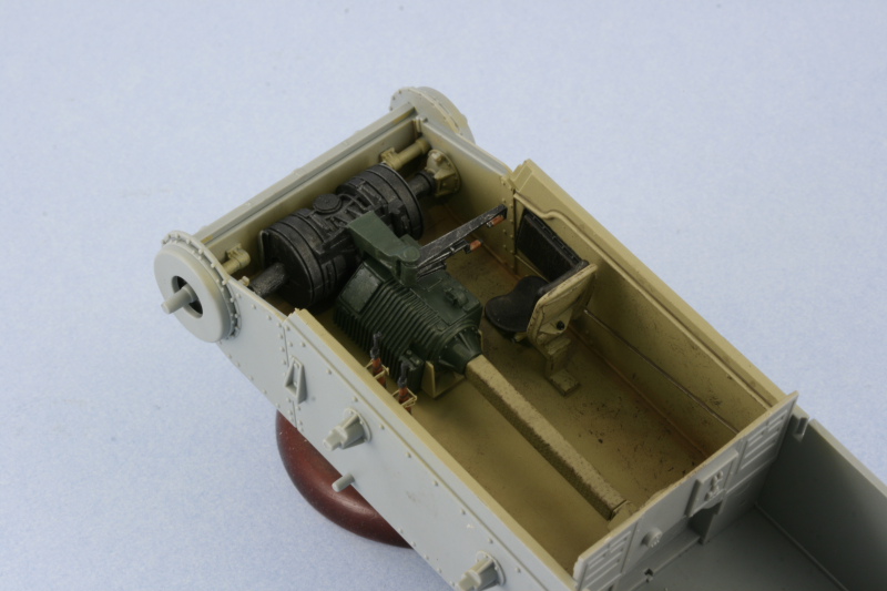
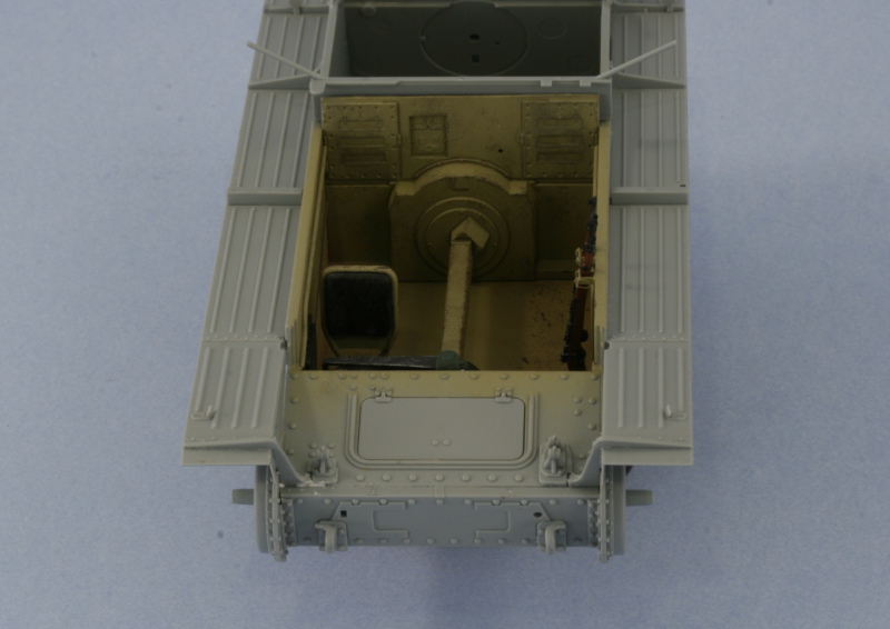
I skipped over Step 6 since that installs the suspension and I'm not ready to do that just yet. Step 7 deals with the interior details beginning with the brake housing and transmission. The brake housing is only visible if you elect to have the glacis hatch open but it's still a necessary component to get the transmission and drive-shaft placed properly. Because the end mounts were installed in Step 2, it's imperative that you DO NOT glue parts D46 into the brake housing at this step...if you do, you cannot install the brake housing in place because there isn't enough clearance to achieve that. Parts D46 have a d-shaped end that must be perfectly aligned with the ends in the hull...so I left them off for now. I opted for the styrene version of the driver's controls and assembled and attached the transmission and drive shaft. The drive shaft is a little loose on the transmission square peg so I used the rear bulkhead dry-fit to help it set up in the proper position and alignment.
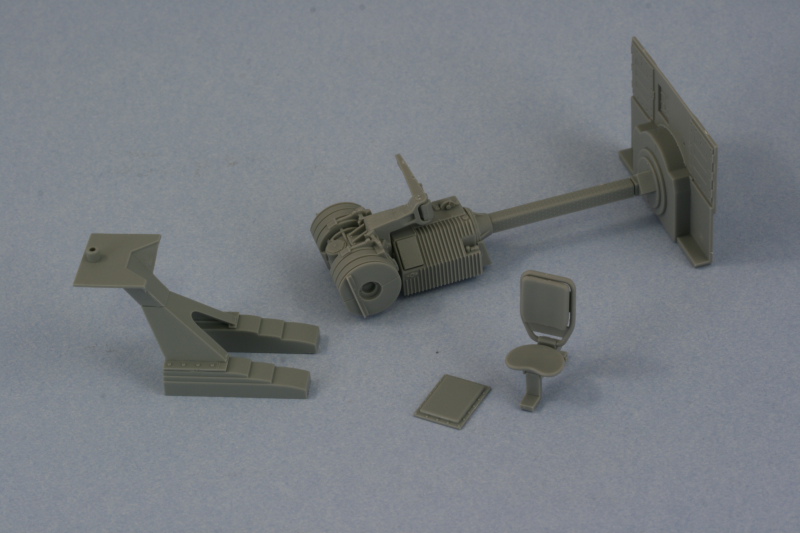
Also included in this step is the driver's seat. I must say I'm extremely disappointed in this area...the seat mount is 100% wrong...and it's something DML has known about since this came off the 38t G sprue and yet they've perpetuated it into this kit. Probably too expensive to correct the entire sprue mold, but that doesn't excuse the fact that the mount is pure fantasy. The seat itself is also very inaccurate...it doesn't have a cushion for the bottom but does provide one for the top. There are no straps for that cushion on the back portion of the rest but they do replicate the ratchet details for the seat adjuster correctly...go figure.
Step 7 also calls for the assembly of the front hull plate. As with the rear hull plate, it's easier to install the plate first and then add details to it. The mounts for the tow hooks were installed first and, just as with the rear, the hooks needed their tabs trimmed down to fit properly.
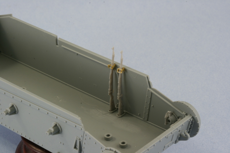
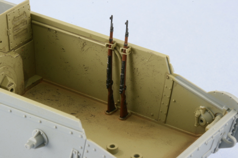
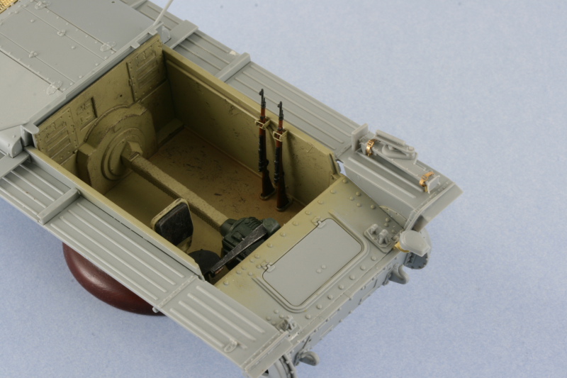
The next little interior detail was the racks for the K98 rifles...there are two and are a combination of styrene and PE parts. The bases are styrene and mold locator lines are provided in the lower hull. The are locator lines for the PE top portions as well...but the kit doesn't provide any rifles. I scrounged around in my spares bin and located a pair, with some careful gymnastics, the rifles can be taken in and out of the racks so they will be painted separately and then installed. These racks aren't called out in the instructions until Step 18 and it's much easier to install them now rather than wait until then when there's a lot more in the way and a whole lot less room to maneuver the rifles.
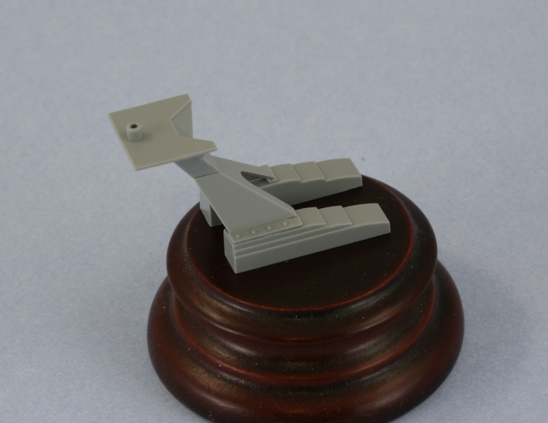
Another interior detail got attention at this point, the pedestal mount for the sIG 33. This is also called out in Step 18 but I went ahead and assembled it now so it could be painted before installation. The choice is provided for either the stacked stair-step style mount or simple I-beam mounts, I opted for the stair-step style. The assembly is a delicate one as the bases are free standing and the only thing holding them together is the pyramid shaped top portion...which is attached to two small base pieces in turn. I made sure to assemble this on a level surface and insured the bases were square as this is an integral piece for mounting the gun.
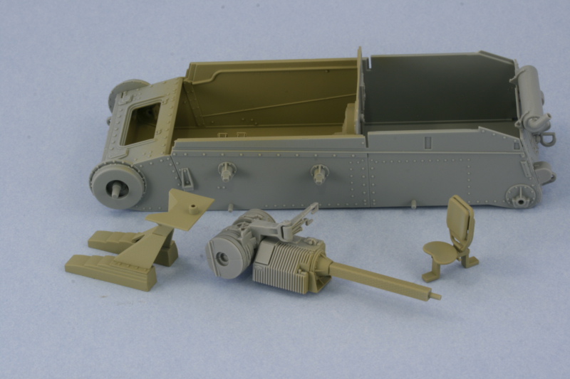
These are all the separate interior pieces assembled today...they will be painted separately from the lower hull and then installed after they've been detailed.
Total Session Time: 6 hours
Total Time to Date: 8.5 hours
First up was the completion of the items in Step 2. This installs the return roller mounts and final drive housings to the exterior. It also calls for the installation of the idler mounts but I'm leaving that off until later to allow for more flexibility when the time comes to mount the tracks and get the proper position/tension. This step also calls for the installation of the ends of the final drive shafts, something that after I had installed them I think would've been better to wait on due to the way the brake housing and actual shafts install into them, more on that in just a bit.
Step 3 deals with the assembly of the rear hull plate details but since the plate itself doesn't get installed to the hull until Step 5, I decided to rearrange things a bit and installed the plate first, then added the details. This proved to be a wise approach especially in regards to the muffler mounts as they have a very small surface area to mount to and it's best done on a stable platform.
The muffler assembly requires a modification to the exhaust pipe to allow it to be positioned at the correct angle instead of vertical and the instructions point out that the pipe needs the tab cut away to do this, easily done with sprue cutters and cleaned up with a #11 knife. The instructions include a helpful diagram to get the pipe aligned at the correct angle and the easiest way to achieve this is to glue the pipe into the muffler then use the diagram like you would any line drawing and rotate it to match the angle. I also enlarged the hole in the pipe with the point of #11 knife as it appeared too small for my liking. The seam from the two part assembly was sanded down and a test fit of the pipe that enters the hull showed the hole in the hull was too small...so I used a round needle file to enlarge it to the right diameter. The armored cover also required some adjustment with the needle file to have sufficient clearance to mount flush to the hull.
The rest of the details were added, the step gives you the option of armored or unarmored idler covers but only the armored are appropriate. An option is provided for the tow hitch and I chose the one with the rectangular latch vs. the open hook based on reference photos. The armored cover was added to the round transmission hatch and the rear tow hooks installed. Some putty was required to fill gaps on the molded in slots, more on the bottom than on the top. The tow hooks also had to have their tabs trimmed down as they were too large to fit the cutouts provided.
Step 4 deals with the fenders and I skipped that for now but will come back to it shortly. Step 5 calls for the installation of the rear hull plate (already done) and the fenders, so it too was skipped. It's important to note that this step shows the driver's knee pad already installed on the right hull side but doesn't have a part number assigned to it. It's A17 and I will paint and install that separately. This is an error/oversight on DML's part in the instructions and is an easy one to miss if you aren't paying attention.
I skipped over Step 6 since that installs the suspension and I'm not ready to do that just yet. Step 7 deals with the interior details beginning with the brake housing and transmission. The brake housing is only visible if you elect to have the glacis hatch open but it's still a necessary component to get the transmission and drive-shaft placed properly. Because the end mounts were installed in Step 2, it's imperative that you DO NOT glue parts D46 into the brake housing at this step...if you do, you cannot install the brake housing in place because there isn't enough clearance to achieve that. Parts D46 have a d-shaped end that must be perfectly aligned with the ends in the hull...so I left them off for now. I opted for the styrene version of the driver's controls and assembled and attached the transmission and drive shaft. The drive shaft is a little loose on the transmission square peg so I used the rear bulkhead dry-fit to help it set up in the proper position and alignment.
Also included in this step is the driver's seat. I must say I'm extremely disappointed in this area...the seat mount is 100% wrong...and it's something DML has known about since this came off the 38t G sprue and yet they've perpetuated it into this kit. Probably too expensive to correct the entire sprue mold, but that doesn't excuse the fact that the mount is pure fantasy. The seat itself is also very inaccurate...it doesn't have a cushion for the bottom but does provide one for the top. There are no straps for that cushion on the back portion of the rest but they do replicate the ratchet details for the seat adjuster correctly...go figure.
Step 7 also calls for the assembly of the front hull plate. As with the rear hull plate, it's easier to install the plate first and then add details to it. The mounts for the tow hooks were installed first and, just as with the rear, the hooks needed their tabs trimmed down to fit properly.
The next little interior detail was the racks for the K98 rifles...there are two and are a combination of styrene and PE parts. The bases are styrene and mold locator lines are provided in the lower hull. The are locator lines for the PE top portions as well...but the kit doesn't provide any rifles. I scrounged around in my spares bin and located a pair, with some careful gymnastics, the rifles can be taken in and out of the racks so they will be painted separately and then installed. These racks aren't called out in the instructions until Step 18 and it's much easier to install them now rather than wait until then when there's a lot more in the way and a whole lot less room to maneuver the rifles.
Another interior detail got attention at this point, the pedestal mount for the sIG 33. This is also called out in Step 18 but I went ahead and assembled it now so it could be painted before installation. The choice is provided for either the stacked stair-step style mount or simple I-beam mounts, I opted for the stair-step style. The assembly is a delicate one as the bases are free standing and the only thing holding them together is the pyramid shaped top portion...which is attached to two small base pieces in turn. I made sure to assemble this on a level surface and insured the bases were square as this is an integral piece for mounting the gun.
These are all the separate interior pieces assembled today...they will be painted separately from the lower hull and then installed after they've been detailed.
Total Session Time: 6 hours
Total Time to Date: 8.5 hours
-
Bill Plunk
- Posts: 1245
- Joined: Wed Sep 28, 2022 10:18 pm
WIP 03-22-2009
Work continued from yesterday with the interior parts airbrushed with a base coat of 80/20 Dunkelgelb/Light Gray. Rather than mask off the contact points for the glacis and the rear bulkhead, I used the actual parts to perform that task since they are a tight friction fit and no glue or poster blue tack was necessary.
The Kar98 rifles were hand painted with the details done using the magnifier and then carefully installed. The interior was weathered by first stippling Burnt Umber using a round 0 sable brush to create a scuffed/scraped look for the high traffic areas where the crew would stand and serve the gun. The actual vehicle had tread plate on the floor but DML provides only the smooth surface since the hull is a direct copy from the 38tG gun-tank which didn't have a tread plate floor. After the Burnt Umber had dried, I stippled in some of the base coat color to blend things back in and make it appear more random. Dirt/dust accumulation effects were added using Mig Europe Dust pigment applied dry and scrubbed into the corners and blended into the scuff/scraped areas using both a dry and wet end of a q-tip. A pin wash of Raw Umber was applied to the raised detail, such as it is, to complete the look. The driver's knee pad was also installed.
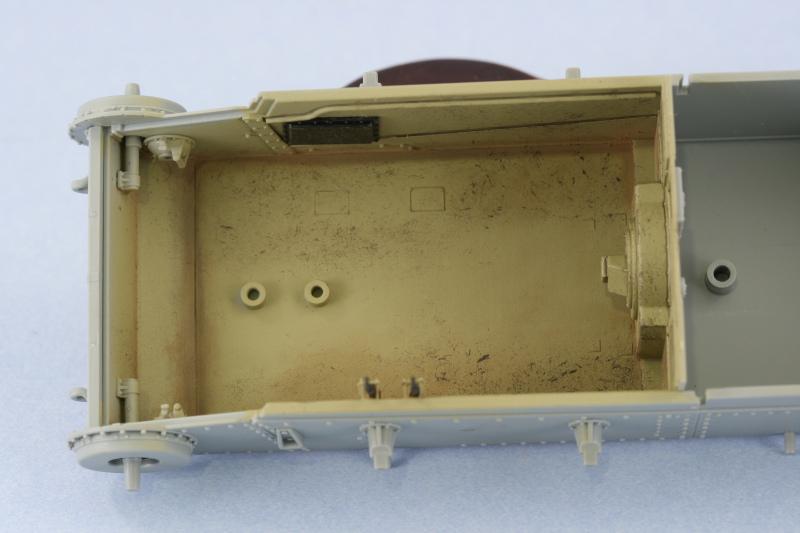
The rear bulkhead was removed and reattached to the drive shaft to create one big assembly for the brake housing/transmission/drive shaft and installed into the hull floor. The drive axles, parts D46, were then installed to join the brake housing to the drive ends already installed into the hull in Steps 1/2. This is not the way, in hindsight, I would recommend doing this as getting the axles into position was a wrestling match and much harder than if the ends had been attached to the axle ends and then installed as one unit with the brake housing.
With the interior complete, it was time to go back to Step 4 and get the fenders ready for installation. I added all of the supports as directed except the front ones because of how they interact with the glacis, I wanted to be sure they were positioned properly.
I'm glad I did that as I encountered a slight problem with the right side fender, more on that in just a bit. The fenders were attached to both sides and I didn't try to introduce any sort of "kink" for fear this would interfere with the attachment of the fighting compartment extensions in later steps. The fenders were glued directly to the hull using the provided molded-on guide using regular glue followed by liquid glue. Once the fenders had set up, I added the front supports and installed the glacis. Once again DML's tendency to copy parts from a previous kit without modification reared its head. The original 38tG glacis plate had a small step on the right side that's not present on the Grille H glacis plate...but the fender support for that side still has the notch to accommodate that step. The result is a noticeable gap which required some careful putty work to fill and correct. The glacis was glued into position and the 3 small parts added as the basis for the gun travel lock. The brake inspection hatch was installed in the closed position
Steps 8, 10, and 11 all deal with the engine and since I have no desire to display the engine hatches open on this build, these steps were skipped. Step 9 calls for the installation of the glacis and inspection hatch which I've already completed. The support for the rear fighting compartment which overhangs the engine bay bulkhead was added and the rear Notek light installed along with the reflectors that I forgot to install in Step 4. This step also calls for the installation of a round brake light on the right side but reference photos don't show this fitted to the Grille H, so I left it off.
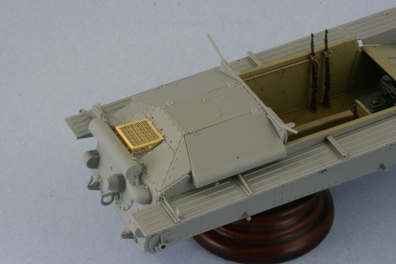
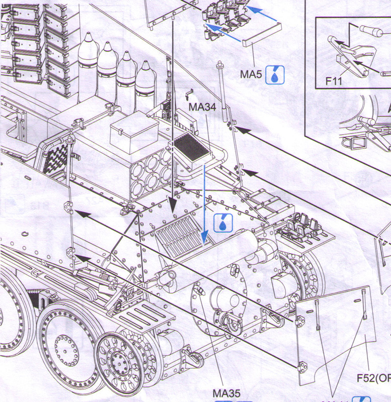
Finishing up the day's activities was the installation of the engine deck and access hatches. Three small holes need to be opened up B12 just above the air intake, which I accomplished using a #74 drill bit and pin vise. The PE screen was added as well and it should be noted that later on in Step 20 this screen vanishes and is instead replaced by another PE part, MA34, which I have no idea why it's there...the part is indeed a screen but it's far too small to cover the provided area...I gave it a try just to see since I was curious as to why there were 2 different screens included on the PE fret. MA20 is the correct screen from what I can tell based on my references and it includes the option to have the sliding metal insert...the few shots I have of the rear of Grille H's don't show this insert as present, so I left it off. The PE screen was attached and the bolts K18 and K19 added by slicing them off the sprue and carefully gluing in position with liquid glue. The three small bolts on the top right hinge for the access hatch were removed per the instructions to allow the perforated shell prep tray to be installed in a later step. The hatches were assembled and added to the engine deck and the entire deck then installed into the hull to complete the step.
Total Session Time: 6.25 hours
Total Time to Date: 14.75 hours
The Kar98 rifles were hand painted with the details done using the magnifier and then carefully installed. The interior was weathered by first stippling Burnt Umber using a round 0 sable brush to create a scuffed/scraped look for the high traffic areas where the crew would stand and serve the gun. The actual vehicle had tread plate on the floor but DML provides only the smooth surface since the hull is a direct copy from the 38tG gun-tank which didn't have a tread plate floor. After the Burnt Umber had dried, I stippled in some of the base coat color to blend things back in and make it appear more random. Dirt/dust accumulation effects were added using Mig Europe Dust pigment applied dry and scrubbed into the corners and blended into the scuff/scraped areas using both a dry and wet end of a q-tip. A pin wash of Raw Umber was applied to the raised detail, such as it is, to complete the look. The driver's knee pad was also installed.
The rear bulkhead was removed and reattached to the drive shaft to create one big assembly for the brake housing/transmission/drive shaft and installed into the hull floor. The drive axles, parts D46, were then installed to join the brake housing to the drive ends already installed into the hull in Steps 1/2. This is not the way, in hindsight, I would recommend doing this as getting the axles into position was a wrestling match and much harder than if the ends had been attached to the axle ends and then installed as one unit with the brake housing.
With the interior complete, it was time to go back to Step 4 and get the fenders ready for installation. I added all of the supports as directed except the front ones because of how they interact with the glacis, I wanted to be sure they were positioned properly.
I'm glad I did that as I encountered a slight problem with the right side fender, more on that in just a bit. The fenders were attached to both sides and I didn't try to introduce any sort of "kink" for fear this would interfere with the attachment of the fighting compartment extensions in later steps. The fenders were glued directly to the hull using the provided molded-on guide using regular glue followed by liquid glue. Once the fenders had set up, I added the front supports and installed the glacis. Once again DML's tendency to copy parts from a previous kit without modification reared its head. The original 38tG glacis plate had a small step on the right side that's not present on the Grille H glacis plate...but the fender support for that side still has the notch to accommodate that step. The result is a noticeable gap which required some careful putty work to fill and correct. The glacis was glued into position and the 3 small parts added as the basis for the gun travel lock. The brake inspection hatch was installed in the closed position
Steps 8, 10, and 11 all deal with the engine and since I have no desire to display the engine hatches open on this build, these steps were skipped. Step 9 calls for the installation of the glacis and inspection hatch which I've already completed. The support for the rear fighting compartment which overhangs the engine bay bulkhead was added and the rear Notek light installed along with the reflectors that I forgot to install in Step 4. This step also calls for the installation of a round brake light on the right side but reference photos don't show this fitted to the Grille H, so I left it off.
Finishing up the day's activities was the installation of the engine deck and access hatches. Three small holes need to be opened up B12 just above the air intake, which I accomplished using a #74 drill bit and pin vise. The PE screen was added as well and it should be noted that later on in Step 20 this screen vanishes and is instead replaced by another PE part, MA34, which I have no idea why it's there...the part is indeed a screen but it's far too small to cover the provided area...I gave it a try just to see since I was curious as to why there were 2 different screens included on the PE fret. MA20 is the correct screen from what I can tell based on my references and it includes the option to have the sliding metal insert...the few shots I have of the rear of Grille H's don't show this insert as present, so I left it off. The PE screen was attached and the bolts K18 and K19 added by slicing them off the sprue and carefully gluing in position with liquid glue. The three small bolts on the top right hinge for the access hatch were removed per the instructions to allow the perforated shell prep tray to be installed in a later step. The hatches were assembled and added to the engine deck and the entire deck then installed into the hull to complete the step.
Total Session Time: 6.25 hours
Total Time to Date: 14.75 hours
-
Bill Plunk
- Posts: 1245
- Joined: Wed Sep 28, 2022 10:18 pm
Edit to 03-22-2009
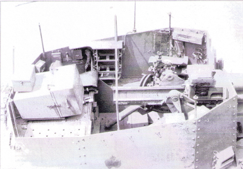
In yesterday's update, I mentioned about the too-small grill that is called for in Step 20, MA34. The primary references that I'm using for this build are MBI's "Marder III & Grille" as well as Panzer Tracts No. 18 but I also flipped through Spielberger's Panzers 35t & 38t and Variants and found the following top-down shot of a Grille H. This is posted for discussion only and to correct my earlier commentary about part MA34.
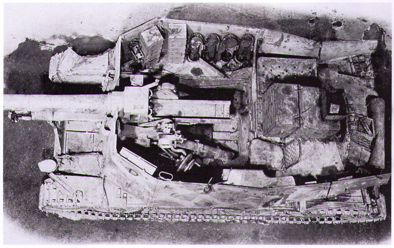
This photo does indeed show some sort of addition on top of the engine intake screen that is smaller than the intake itself but it looks like a sort of field-rigged tray judging by the fact that there's an object inside it. The DML part for this has it as a screen covered raised extension though, so not sure exactly what they were trying to replicate in the end. The scheme on this vehicle is the splinter-type camo and is included in the DML finishing guide so if you wanted to replicate that vehicle it would be accurate, sort of, to mount it. This view also shows this particular vehicle had the sliding tray adjuster for the regular screen...which intrigued me further. Pics of the initial production vehicle in MBI don't show this slide present but here it is on an actual vehicle, so again it is an acceptable option if you want to go that route.
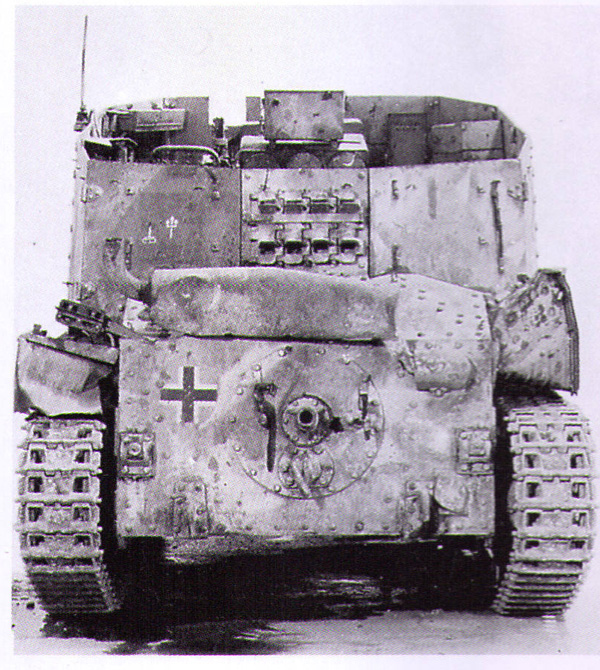
The above pic shows the same vehicle from the rear and also highlights another difference...this one doesn't have the armored covers for the idler mounts or the transmission access. This may indicate that this is a rebuilt earlier 38t converted over to a Grille (after 1942 38t gun-tanks returned for repairs were often converted to either Grilles or Marders as the case required to fill orders) since it also has a vertical exhaust pipe instead of one positioned at an angle but it's hard to say 100% either way. At the very least it certainly provides more room for variety!
This photo does indeed show some sort of addition on top of the engine intake screen that is smaller than the intake itself but it looks like a sort of field-rigged tray judging by the fact that there's an object inside it. The DML part for this has it as a screen covered raised extension though, so not sure exactly what they were trying to replicate in the end. The scheme on this vehicle is the splinter-type camo and is included in the DML finishing guide so if you wanted to replicate that vehicle it would be accurate, sort of, to mount it. This view also shows this particular vehicle had the sliding tray adjuster for the regular screen...which intrigued me further. Pics of the initial production vehicle in MBI don't show this slide present but here it is on an actual vehicle, so again it is an acceptable option if you want to go that route.
The above pic shows the same vehicle from the rear and also highlights another difference...this one doesn't have the armored covers for the idler mounts or the transmission access. This may indicate that this is a rebuilt earlier 38t converted over to a Grille (after 1942 38t gun-tanks returned for repairs were often converted to either Grilles or Marders as the case required to fill orders) since it also has a vertical exhaust pipe instead of one positioned at an angle but it's hard to say 100% either way. At the very least it certainly provides more room for variety!
-
Bill Plunk
- Posts: 1245
- Joined: Wed Sep 28, 2022 10:18 pm
WIP 03-28-2009
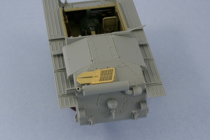
Some more progress to post about today, normally I also get some time in on Friday nights but since yesterday was my birthday, I was a little "distracted" shall we say. Picking up from last weekend's update, I did some more browsing of reference photos and decided that the prototype photo that didn't have the sliding portion of the air intake was in the minority, so I went ahead and added the slide along with the tiny locking wing nut. Looking at those same photos, I noticed that the reflectors weren't present so those were removed and the points where they were glued carefully sanded down to remove the marks left behind. The presence of the extra raised screen on the intake seems to be a 50-50 proposition though...so I still kept that one off.
I also noticed that back in Step 5 I had missed the installation of parts F50/51 which are additional side supports for the fighting compartment. These are shown already installed in place in that step and have number call-outs but I overlooked it since it's the step that installs the fenders and the rear hull plate.
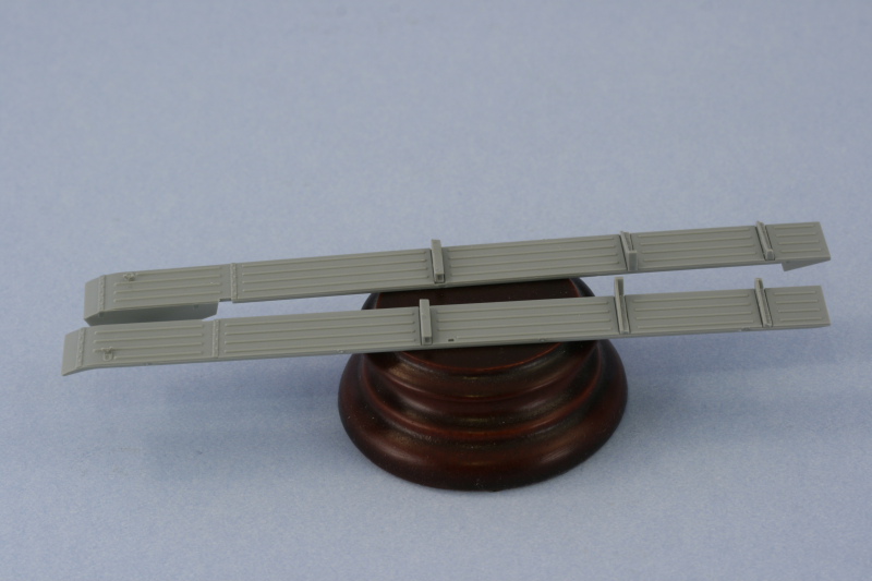
Steps 13 and 14 deal with the assembly and installation of the various tools and gear on the fenders and includes overhead diagrams showing the layouts for both the left and right sides. I removed all the tools from the sprues and cleaned them up but will not install them until after I've painted the exterior and before the fighting compartment sides are installed. The tools all require PE straps to be added, that will be done after they are painted as well. The tools are all "standard" Pz38t tools but the layout for the pick and shovel in particular are where the biggest changes are. The shovel blade is too thick to fit where intended against the rear hull side, so it was sanded down considerably to thin it out and get it down to the right size. Curiously the fender layout on the left side overlooks the large crowbar, part K1, but in Step 15 it's shown as already installed, so you have to be watching or you'll miss it.
I also constructed all of the spare track runs using the provided Magic track links. One run of 7 for the hull nose, one run of 2 for the right rear fender, one run of 5 for the right front fender, and one run of 4 for the rear fighting compartment exterior. The end links were drilled out using a #74 bit in a pin vise to simulate the missing pins and open holes on those links. Some of the links had raised ejector marks that required clean-up while others didn't, so not too much work required there.
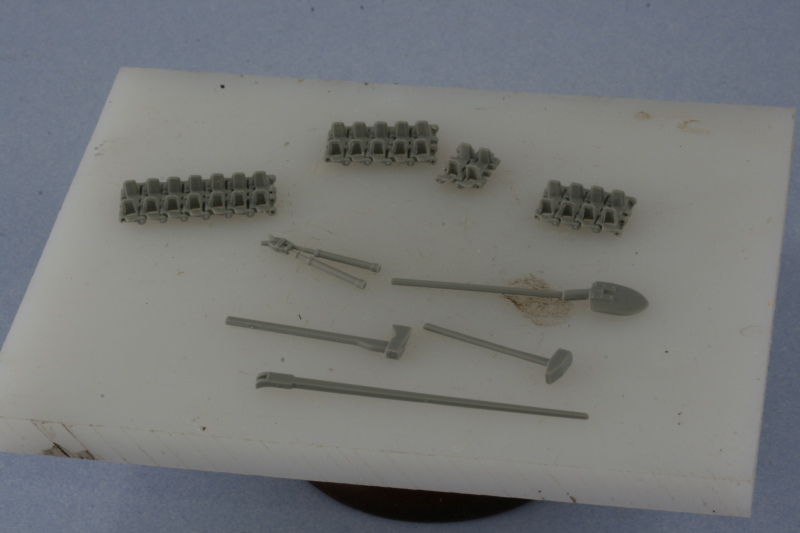
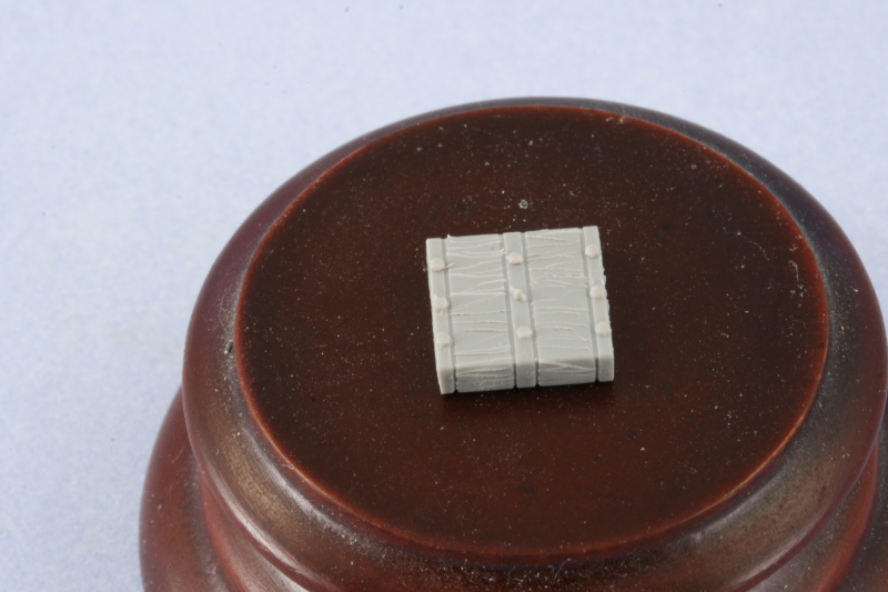
One of the biggest let-downs for me in the tools department was the jack block. This one comes off the B sprue and while the instruction diagram shows it as nicely detailed with raised bolt detail for the binding straps, the actual part looks nothing like that. With the exception of the small wing-nut in the center, the part is devoid of any detail. I added the missing bolt heads using the leftover K18 bolt heads and created some wood grain pattern using the tip of a #11 blade and a magnifier.
Rounding things out for these steps was the assembly and installation of the jack and the front Notek light. The jack assembled without any issues but I had a major problem with the kit-provided PE retaining straps. The bend lines are extremely fragile and once bent, don't tolerate much movement/handling before coming apart. I found this out the hard way with the first strap while attempting to fit/adjust it...it fragmented into 3 different pieces while test fitting, so I had to scrounge replacements from my PE spares bin. These were added to the PE bases using CA gel and then bent to shape to secure the jack in place.
The Notek light base was installed first to the fender bracket using Gator Grip glue. Then the base of the Notek was added with the same glue, carefully positioning it in the correct forward position. Once dry, the hood/lamp portion was added using liquid glue to complete the assembly.
I stopped work here because the next sections are the fighting compartment sides and I wanted plenty of time to work with them in individual sessions, so that will be on the agenda for tomorrow's efforts.
Total Session Time: 4.75 hours
Total Time to Date: 19.5 hours
I also noticed that back in Step 5 I had missed the installation of parts F50/51 which are additional side supports for the fighting compartment. These are shown already installed in place in that step and have number call-outs but I overlooked it since it's the step that installs the fenders and the rear hull plate.
Steps 13 and 14 deal with the assembly and installation of the various tools and gear on the fenders and includes overhead diagrams showing the layouts for both the left and right sides. I removed all the tools from the sprues and cleaned them up but will not install them until after I've painted the exterior and before the fighting compartment sides are installed. The tools all require PE straps to be added, that will be done after they are painted as well. The tools are all "standard" Pz38t tools but the layout for the pick and shovel in particular are where the biggest changes are. The shovel blade is too thick to fit where intended against the rear hull side, so it was sanded down considerably to thin it out and get it down to the right size. Curiously the fender layout on the left side overlooks the large crowbar, part K1, but in Step 15 it's shown as already installed, so you have to be watching or you'll miss it.
I also constructed all of the spare track runs using the provided Magic track links. One run of 7 for the hull nose, one run of 2 for the right rear fender, one run of 5 for the right front fender, and one run of 4 for the rear fighting compartment exterior. The end links were drilled out using a #74 bit in a pin vise to simulate the missing pins and open holes on those links. Some of the links had raised ejector marks that required clean-up while others didn't, so not too much work required there.
One of the biggest let-downs for me in the tools department was the jack block. This one comes off the B sprue and while the instruction diagram shows it as nicely detailed with raised bolt detail for the binding straps, the actual part looks nothing like that. With the exception of the small wing-nut in the center, the part is devoid of any detail. I added the missing bolt heads using the leftover K18 bolt heads and created some wood grain pattern using the tip of a #11 blade and a magnifier.
Rounding things out for these steps was the assembly and installation of the jack and the front Notek light. The jack assembled without any issues but I had a major problem with the kit-provided PE retaining straps. The bend lines are extremely fragile and once bent, don't tolerate much movement/handling before coming apart. I found this out the hard way with the first strap while attempting to fit/adjust it...it fragmented into 3 different pieces while test fitting, so I had to scrounge replacements from my PE spares bin. These were added to the PE bases using CA gel and then bent to shape to secure the jack in place.
The Notek light base was installed first to the fender bracket using Gator Grip glue. Then the base of the Notek was added with the same glue, carefully positioning it in the correct forward position. Once dry, the hood/lamp portion was added using liquid glue to complete the assembly.
I stopped work here because the next sections are the fighting compartment sides and I wanted plenty of time to work with them in individual sessions, so that will be on the agenda for tomorrow's efforts.
Total Session Time: 4.75 hours
Total Time to Date: 19.5 hours
-
Bill Plunk
- Posts: 1245
- Joined: Wed Sep 28, 2022 10:18 pm
WIP 03-29-2009
I tried to make the most out of today's efforts since I know I won't be able to do any work on this next weekend due to a business trip to Fiji that requires me to leave on a Saturday in order to arrive on a Tuesday...got to love the International Date Line!
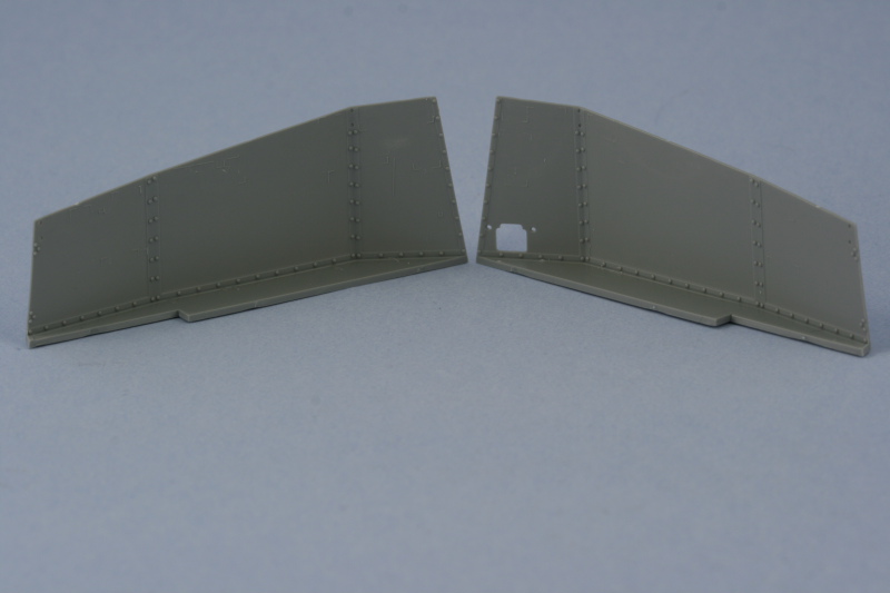
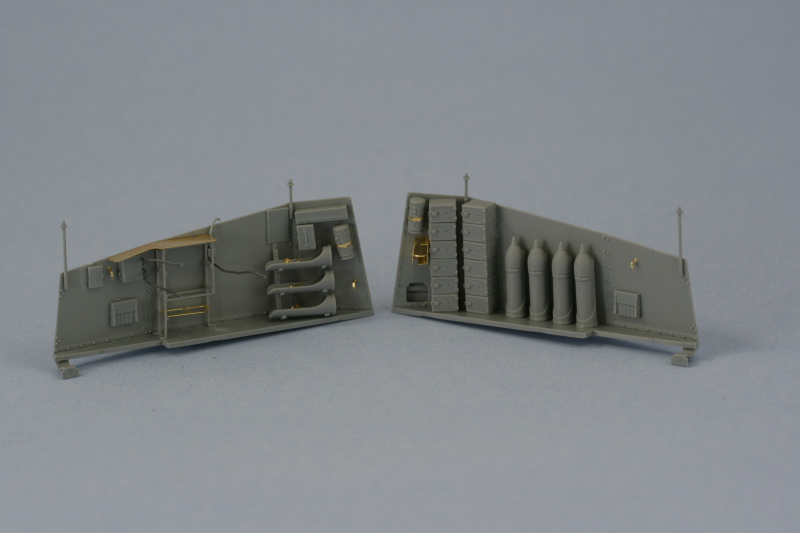
My goal was to get the interior of the fighting compartment completed and I met it but it took a lot longer than I had anticipated. I started in on Step 16 which is a monster of a step with lots of sub diagrams and parts to deal with for the left hand side. The first order of business was to remove several unnecessary molded on locator marks as directed in the instructions. The little box that highlights them in blue misses a couple though, so you have to check carefully to be sure you're getting them all. I did this for both sides and used a micro-chisel on some of the harder to reach ares while the rest were removed with a #11 blade. I should also note that you have to be very careful removing the sides from the sprues as the tops in particular are very thin and it's easy to gouge them if you aren't paying attention.
The first item of importance was dealing with all the various and sundry radio gear and power/transformer equipment. Since I intend to wire these up using 0.5mm solder, the appropriate holes were drilled out using a pin vise while the actual wiring will be added later after things are painted and installed. The instructions contain an error in the call-out for the intercom box, it's labelled RA48 when it really is just RA8. I was originally going to use part F85 (it's hidden on the F sprue but there if you look closely) but it tweezerpulted into oblivion, so I had to use the not-for-use part F1 which is designed for the Grille M. The wire has to be re-bent in the opposite direction but otherwise is the same. The radio rack is an exercise in patience to assemble...it's a two-part styrene assembly with a 3rd PE insert to hold the smaller transformer, but each of the styrene parts has 7-8 nodules or sprue attachment points that have to be cleaned up...and since they are very fragile, a new sharp blade will serve you best here. The frames were assembled and the PE insert added alone instead of attached to the transformer as the instructions would have you do it.
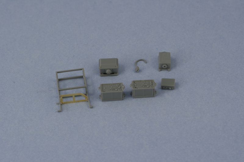
The rack was then installed into position and all of the various gear dry fit to insure it would all play nice together. The smaller transformer that sits on the PE insert had to be sanded down in order to fit into its allotted space. This is a direct result of these parts being reused parts (the RA and RB sprues are generic radio parts) instead of parts specifically designed for the rack they go into. Otherwise everything else fit tight but manageable. I added the solder wiring to the antenna junction box and the intercom box before installing them into the side and left plenty of wire to work with which will be cut down later after painting and the radios are installed. I opted for the PE rain guard for the radios but the instructions are a little vague on how exactly it's supposed to install. The PE part doesn't have a bend line etched into it, so I used pliers and carefully introduced the slight angle that it needs in order to sit properly and flush with the top edge of the side.
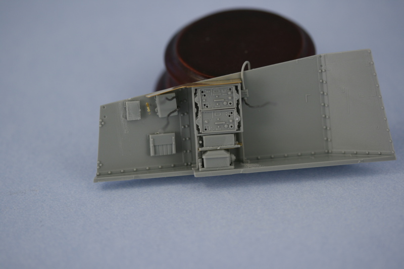
Next I installed all the various boxes and the gas mask container to the front areas as called for with their locator marks. The gas mask PE mount is more complex than it needs to be...it's 3 parts, one for the base, one for the curved holders, and a 3rd for the strap itself. You end up stacking the three parts together and then strapping the container in place and all the detail is hidden as a result...the only benefit from this approach is if you want to show the holder empty. The three shell holders and rack were assembled and I opted to show these empty since it would be extremely tough to paint the rounds once installed and in place. The kit only includes enough parts to show one side or the other empty, but not both, so the right side will have the full racks. Construction of the racks is a tricky exercise, the instructions just show the holders already attached to the racks and then the rack installed into place. I got around this by first gluing F24, the front rack bar, in position without attaching the round holders. The holders were then glued into F25, the rear rack bar, and then glued into place. I used liquid glue to position the "free" ends of the holders into the slots on F24...getting a level and properly angled rack in the process.
I deliberately left of the small seat cushion and the MP40 holder since they would get in the way of adding the radio equipment and completing the wiring, but they were cleaned up and set off to the side for later.
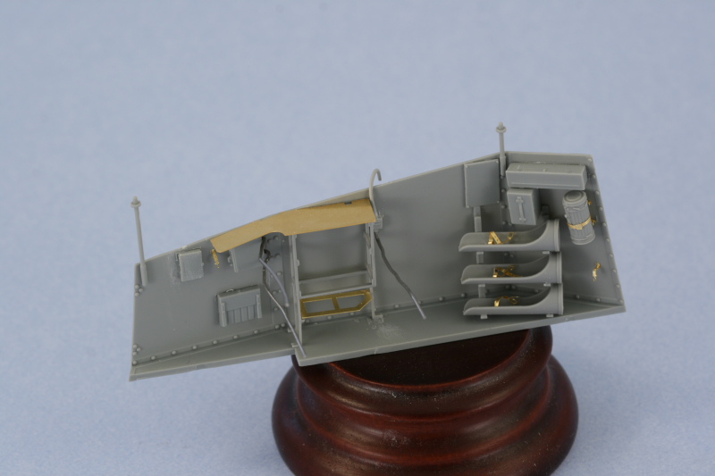
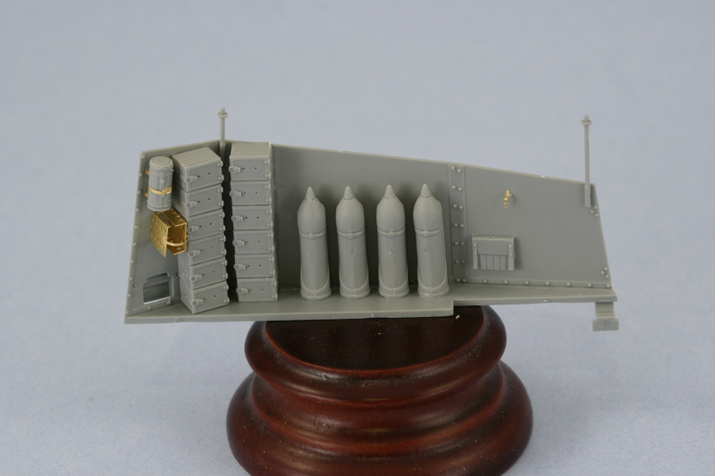
That finished up Step 16, so it was on to 17! This dealt with the right side and the first order of business was to assemble the 12 charge boxes. 10 required the molded on top and bottom ridges to be removed while 2 only required the bottom removed.
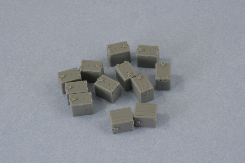
The boxes were then assembled into 2 stacks of 6 each and installed into position. The right stack ends up being taller than it's supposed to be judging by reference photos but by removing 2 rivets on the bracing panel I was able to get it to sit virtually flush with the top of the superstructure side. The left stack sits at the proper height, so not sure what the cause is other than the dimensions on the boxes are incorrect. They don't have to be off by much...just a fraction of a mm each to produce this kind of compound error...but it's there.
The 4 shell racks were added as well...and aside from the instruction diagram, no guidance is provided on their location. I added the first and then the fourth to set the distance and then spaced the second and third as evenly as possible to get them into position. Each shell has a prominent seam that runs top to bottom, so this had to be carefully sanded down with a sanding twig to remove it.
The PE glass block holder was bent to shape and installed in position along with the retaining strap but I decided not to add the block itself as I think it looks better empty. The gas mask container was also added with the MP40 and seat cushion also left off on this side for now.
While looking around on the floor for another part I found the missing F85...but since I'd already wired up F1 and glued it into place, I just snipped off the wire portion and swapped it out with the wire portion on F1...that way it had the right height and spacing and wouldn't require any further modification like F85 would've. I also added the rearmost braces, F34, to both sides and test fit them to the hull to be sure they were in the proper position and angle. So, the results of today's efforts...
Total Session Time: 7 hours
Total Time to Date: 26.5 hours
My goal was to get the interior of the fighting compartment completed and I met it but it took a lot longer than I had anticipated. I started in on Step 16 which is a monster of a step with lots of sub diagrams and parts to deal with for the left hand side. The first order of business was to remove several unnecessary molded on locator marks as directed in the instructions. The little box that highlights them in blue misses a couple though, so you have to check carefully to be sure you're getting them all. I did this for both sides and used a micro-chisel on some of the harder to reach ares while the rest were removed with a #11 blade. I should also note that you have to be very careful removing the sides from the sprues as the tops in particular are very thin and it's easy to gouge them if you aren't paying attention.
The first item of importance was dealing with all the various and sundry radio gear and power/transformer equipment. Since I intend to wire these up using 0.5mm solder, the appropriate holes were drilled out using a pin vise while the actual wiring will be added later after things are painted and installed. The instructions contain an error in the call-out for the intercom box, it's labelled RA48 when it really is just RA8. I was originally going to use part F85 (it's hidden on the F sprue but there if you look closely) but it tweezerpulted into oblivion, so I had to use the not-for-use part F1 which is designed for the Grille M. The wire has to be re-bent in the opposite direction but otherwise is the same. The radio rack is an exercise in patience to assemble...it's a two-part styrene assembly with a 3rd PE insert to hold the smaller transformer, but each of the styrene parts has 7-8 nodules or sprue attachment points that have to be cleaned up...and since they are very fragile, a new sharp blade will serve you best here. The frames were assembled and the PE insert added alone instead of attached to the transformer as the instructions would have you do it.
The rack was then installed into position and all of the various gear dry fit to insure it would all play nice together. The smaller transformer that sits on the PE insert had to be sanded down in order to fit into its allotted space. This is a direct result of these parts being reused parts (the RA and RB sprues are generic radio parts) instead of parts specifically designed for the rack they go into. Otherwise everything else fit tight but manageable. I added the solder wiring to the antenna junction box and the intercom box before installing them into the side and left plenty of wire to work with which will be cut down later after painting and the radios are installed. I opted for the PE rain guard for the radios but the instructions are a little vague on how exactly it's supposed to install. The PE part doesn't have a bend line etched into it, so I used pliers and carefully introduced the slight angle that it needs in order to sit properly and flush with the top edge of the side.
Next I installed all the various boxes and the gas mask container to the front areas as called for with their locator marks. The gas mask PE mount is more complex than it needs to be...it's 3 parts, one for the base, one for the curved holders, and a 3rd for the strap itself. You end up stacking the three parts together and then strapping the container in place and all the detail is hidden as a result...the only benefit from this approach is if you want to show the holder empty. The three shell holders and rack were assembled and I opted to show these empty since it would be extremely tough to paint the rounds once installed and in place. The kit only includes enough parts to show one side or the other empty, but not both, so the right side will have the full racks. Construction of the racks is a tricky exercise, the instructions just show the holders already attached to the racks and then the rack installed into place. I got around this by first gluing F24, the front rack bar, in position without attaching the round holders. The holders were then glued into F25, the rear rack bar, and then glued into place. I used liquid glue to position the "free" ends of the holders into the slots on F24...getting a level and properly angled rack in the process.
I deliberately left of the small seat cushion and the MP40 holder since they would get in the way of adding the radio equipment and completing the wiring, but they were cleaned up and set off to the side for later.
That finished up Step 16, so it was on to 17! This dealt with the right side and the first order of business was to assemble the 12 charge boxes. 10 required the molded on top and bottom ridges to be removed while 2 only required the bottom removed.
The boxes were then assembled into 2 stacks of 6 each and installed into position. The right stack ends up being taller than it's supposed to be judging by reference photos but by removing 2 rivets on the bracing panel I was able to get it to sit virtually flush with the top of the superstructure side. The left stack sits at the proper height, so not sure what the cause is other than the dimensions on the boxes are incorrect. They don't have to be off by much...just a fraction of a mm each to produce this kind of compound error...but it's there.
The 4 shell racks were added as well...and aside from the instruction diagram, no guidance is provided on their location. I added the first and then the fourth to set the distance and then spaced the second and third as evenly as possible to get them into position. Each shell has a prominent seam that runs top to bottom, so this had to be carefully sanded down with a sanding twig to remove it.
The PE glass block holder was bent to shape and installed in position along with the retaining strap but I decided not to add the block itself as I think it looks better empty. The gas mask container was also added with the MP40 and seat cushion also left off on this side for now.
While looking around on the floor for another part I found the missing F85...but since I'd already wired up F1 and glued it into place, I just snipped off the wire portion and swapped it out with the wire portion on F1...that way it had the right height and spacing and wouldn't require any further modification like F85 would've. I also added the rearmost braces, F34, to both sides and test fit them to the hull to be sure they were in the proper position and angle. So, the results of today's efforts...
Total Session Time: 7 hours
Total Time to Date: 26.5 hours
-
Bill Plunk
- Posts: 1245
- Joined: Wed Sep 28, 2022 10:18 pm
WIP 03-30-2009
I managed to sneak in some rare non-weekend bench time this evening and put in some effort with Step 18. I thought this would proceed smoothly but hit a snag in relation to the large 6 round box that mounts to the engine deck. I followed the instructions guidance in attaching the PE frame to the underside but when I test fit it to the engine deck immediately realized that there was a size problem.
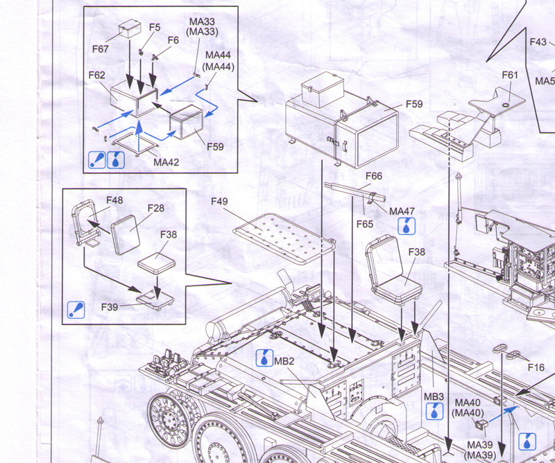
In checking the layout in the MBI book, the "feet" of the mount are placed with the rear foot just ahead of the rear engine hatch hinge and the front foot 2 rivets behind the front engine hatch hinge. In reality, the frame doesn't position there at all...it's too large...so I flipped ahead in the instructions to see what the diagrams showed.
In Step 19, the front of the box is shown virtually flush with open edge of the lower compartment right above the bulk head to the engine compartment.
Again in Step 20, looking from the rear, it shows one foot just ahead of the rear hinge but the front foot is on top of the front hinge.
This confirmed to me that the DML design of both the box and the support frame have it too large vs. the MBI photo. To accommodate this, DML moved the box forward in the installation to be flush with the bulk head...but it's not the right position. To address this, it's necessary to position the rear foot behind the rear hinge and not in front...and then the front foot can be positioned in the proper 2 rivets behind the front hinge position...after you remove the rivets of course. Rivets needed to be removed for both the front and rear feet to mount cleanly to the hatch and in the proper position. Once those were out of the way, I installed the box into position. The PE details for the side latches were then added along with the PE handles. The perforated side tray was also added along with the little triangular "wing" PE extensions for the hull sides.

It's also worth noting that DML got another small detail wrong...the small box that mounts on top of the ready round box is mounted on some small shims to make it sit level instead of slightly angled...I noticed this after I'd already glued it down and didn't want to pry it up and go through the sanding and cleanup from already being glued down to elevate it a fraction of a mm to replicate the look, but it's something for others to be aware of should they choose to add this little detail. I left the commander's seat off for now to better facilitate painting and detailing, it will get added later on. Same thing with the cleaning rods which are supposed to peak out from under the large ammo box and of course the compartment sides have been left separate to facilitate their painting as well.
Total Session Time: 1.75 hours
Total Time to Date: 28.25 hours
In checking the layout in the MBI book, the "feet" of the mount are placed with the rear foot just ahead of the rear engine hatch hinge and the front foot 2 rivets behind the front engine hatch hinge. In reality, the frame doesn't position there at all...it's too large...so I flipped ahead in the instructions to see what the diagrams showed.
In Step 19, the front of the box is shown virtually flush with open edge of the lower compartment right above the bulk head to the engine compartment.
Again in Step 20, looking from the rear, it shows one foot just ahead of the rear hinge but the front foot is on top of the front hinge.
This confirmed to me that the DML design of both the box and the support frame have it too large vs. the MBI photo. To accommodate this, DML moved the box forward in the installation to be flush with the bulk head...but it's not the right position. To address this, it's necessary to position the rear foot behind the rear hinge and not in front...and then the front foot can be positioned in the proper 2 rivets behind the front hinge position...after you remove the rivets of course. Rivets needed to be removed for both the front and rear feet to mount cleanly to the hatch and in the proper position. Once those were out of the way, I installed the box into position. The PE details for the side latches were then added along with the PE handles. The perforated side tray was also added along with the little triangular "wing" PE extensions for the hull sides.
It's also worth noting that DML got another small detail wrong...the small box that mounts on top of the ready round box is mounted on some small shims to make it sit level instead of slightly angled...I noticed this after I'd already glued it down and didn't want to pry it up and go through the sanding and cleanup from already being glued down to elevate it a fraction of a mm to replicate the look, but it's something for others to be aware of should they choose to add this little detail. I left the commander's seat off for now to better facilitate painting and detailing, it will get added later on. Same thing with the cleaning rods which are supposed to peak out from under the large ammo box and of course the compartment sides have been left separate to facilitate their painting as well.
Total Session Time: 1.75 hours
Total Time to Date: 28.25 hours
-
Bill Plunk
- Posts: 1245
- Joined: Wed Sep 28, 2022 10:18 pm
WIP 04-03-2009
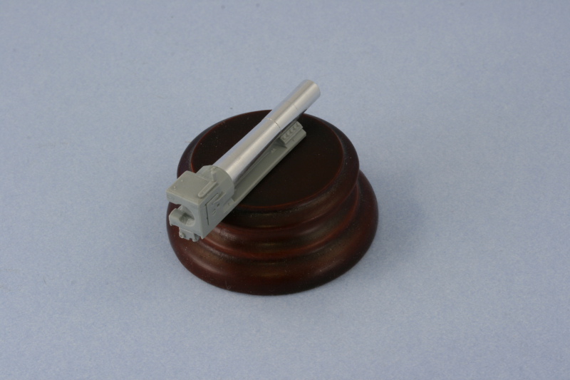
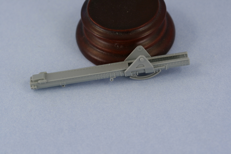
Since I will be out of town this weekend, I decided to get in as much time as I could squeeze in here and there to at least get the final pre-paint steps done. The biggest item of business was the sIG 33 gun, so work began there in Step 21. The step calls for assembly of the breech block first and has two halves for the breech and 4 parts for the sliding block. The instructions are a little vague when it comes to part B14 and indicates that you should glue this directly to the sliding block part B5...but I found it was better to glue it into the assembled block halves and leave the sliding block able to move freely. The assembly uses an insert for the top of the block to avoid a large seam but some sanding was still necessary around its edges to get a seamless look. The same was true of the interior of the two halves which I carefully sanded with a round needle file to avoid damaging the detail there.
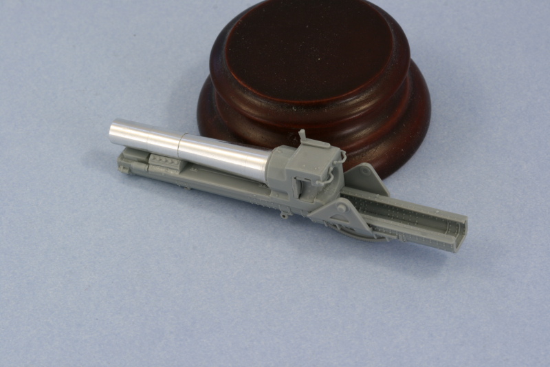
The second portion of the step adds the front part of the recoil sled along with the aluminum barrel. I added the recoil sled portion first so that it would have a solid/level connection with the breech block and let that dry. The small join with the block was lightly sanded and then the barrel added using CA gel at the base as well as the front where the barrel hoop attaches to the sled.
Next came the gun mount and tray in Step 22 and 23. This is a complex step with a lot of sub-diagrams, so you need to decide your angle of attack first. I started with the tray, which assembles out of 3 parts to avoid the longitudinal seam common in other kits. The contact surfaces for this approach are small though, so I glued the bottom piece first to one side using regular glue and then repeated for the other side once the glue had set up a little. I used the recoil sled from the previous step to test-fit and make sure the width was correct. Then I added the insert that completes the top portion of the tray using liquid glue to get it to align properly since the thin rear portions in particular needed to be aligned very carefully. The two small grab bars on the breech block were also added...a feature that wasn't always present on sIG 33 guns but which matches the style of this particular one that DML included.
Next up were the two halves of the mount and the recoil cylinders. The right side of the mount is pretty simple while the left one is more complex since it also includes the elevation gears and gun sight. The sub-assembly diagrams for the elevation gears asks for a nearly impossible construction sequence where you add the different components to the wheel box and then install to the side of the mount. I ignored this except for the parts number call-outs and instead installed the two different gear elements, parts C13 and C7, into their proper positions on the mount side first. Then I added the gear box C10 and it's connection conduit part C6 to insure the proper alignment and fit of all the parts. Last but not least the hand wheels were then added.
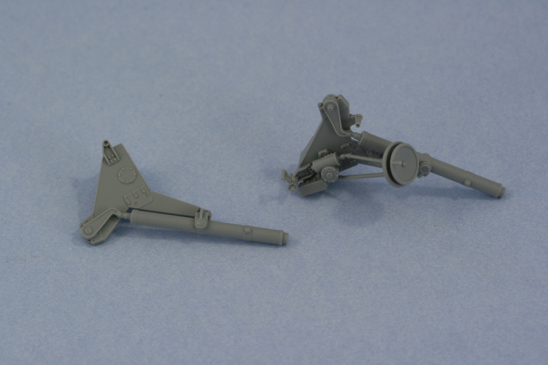
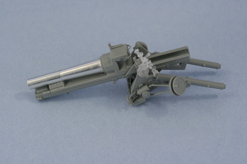
Everything was then brought together to complete the mount assembly. The instructions do not tell you this, but if you don't glue the tops of parts F46 and F47 to the trunnion points on the recoil tray, the gun can remain positionable for later installation. If you do glue them into position, be sure you've got the right elevation set or you'll be stuck otherwise. I also assembled the gun sight, opting for the short neck version since the Grille H has a cut-out in the front superstructure whereas the long neck is more common on the Grille M and Bison I that didn't have that type of cutout available. The elevation arms on the gradient gear had two small holes molded into them, these are not ejector marks but should be there however DML didn't mold them all the way open for some reason...so this was cured using a pin vise and drill bit.
I've left the recoil sled and gun dry fit for now to facilitate detail painting later on...it's a very tight fight as is, so no glue is actually required unless you choose to use it for a permanent join.
Returning back to Step 19, I added the details to the interior and exterior of the front superstructure plate. The driver's visor had a very tiny slit molded into it, so I opened this up a bit more using the tip of a needle file and then cleaned it up with a #11 blade. No armored glass block is provided for, I'm not sure if one was supposed to be fitted or not on this particular vehicle but it seems strange for it to be absent.
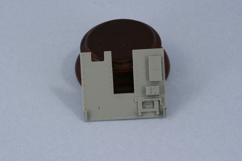
Details were also added to the front of the superstructure plate and a word of warning is appropriate here. The diagrams direct the installation of the sliding heavy additional front plate, part F60, and it's spring-loaded hinged plate F69 in the position that's appropriate for the gun in the travel level elevation position. If you decide to pose the gun in an elevated or firing position, you will need to adjust the position of both parts, not just the spring-loaded hinged part. I'm going to have mine in the level position and may or may not engage the lock, so that's not a problem for me but it is a trap for the unwary if you're doing a dio or similar where you decide on something different elevation-wise.
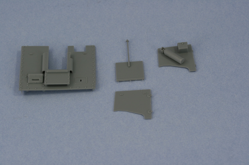
I also cleaned up the rear compartment doors and installed the fire extinguisher and small box to the left door. The rear fixed panel received the canvas cover pole while the right door was cleaned up in preparation for paint and didn't have any parts required.
That's all the construction that will be completed before the superstructure interior is painted.
Total Session Time: 4.5 hours
Total Time to Date: 32.75 hours
The second portion of the step adds the front part of the recoil sled along with the aluminum barrel. I added the recoil sled portion first so that it would have a solid/level connection with the breech block and let that dry. The small join with the block was lightly sanded and then the barrel added using CA gel at the base as well as the front where the barrel hoop attaches to the sled.
Next came the gun mount and tray in Step 22 and 23. This is a complex step with a lot of sub-diagrams, so you need to decide your angle of attack first. I started with the tray, which assembles out of 3 parts to avoid the longitudinal seam common in other kits. The contact surfaces for this approach are small though, so I glued the bottom piece first to one side using regular glue and then repeated for the other side once the glue had set up a little. I used the recoil sled from the previous step to test-fit and make sure the width was correct. Then I added the insert that completes the top portion of the tray using liquid glue to get it to align properly since the thin rear portions in particular needed to be aligned very carefully. The two small grab bars on the breech block were also added...a feature that wasn't always present on sIG 33 guns but which matches the style of this particular one that DML included.
Next up were the two halves of the mount and the recoil cylinders. The right side of the mount is pretty simple while the left one is more complex since it also includes the elevation gears and gun sight. The sub-assembly diagrams for the elevation gears asks for a nearly impossible construction sequence where you add the different components to the wheel box and then install to the side of the mount. I ignored this except for the parts number call-outs and instead installed the two different gear elements, parts C13 and C7, into their proper positions on the mount side first. Then I added the gear box C10 and it's connection conduit part C6 to insure the proper alignment and fit of all the parts. Last but not least the hand wheels were then added.
Everything was then brought together to complete the mount assembly. The instructions do not tell you this, but if you don't glue the tops of parts F46 and F47 to the trunnion points on the recoil tray, the gun can remain positionable for later installation. If you do glue them into position, be sure you've got the right elevation set or you'll be stuck otherwise. I also assembled the gun sight, opting for the short neck version since the Grille H has a cut-out in the front superstructure whereas the long neck is more common on the Grille M and Bison I that didn't have that type of cutout available. The elevation arms on the gradient gear had two small holes molded into them, these are not ejector marks but should be there however DML didn't mold them all the way open for some reason...so this was cured using a pin vise and drill bit.
I've left the recoil sled and gun dry fit for now to facilitate detail painting later on...it's a very tight fight as is, so no glue is actually required unless you choose to use it for a permanent join.
Returning back to Step 19, I added the details to the interior and exterior of the front superstructure plate. The driver's visor had a very tiny slit molded into it, so I opened this up a bit more using the tip of a needle file and then cleaned it up with a #11 blade. No armored glass block is provided for, I'm not sure if one was supposed to be fitted or not on this particular vehicle but it seems strange for it to be absent.
Details were also added to the front of the superstructure plate and a word of warning is appropriate here. The diagrams direct the installation of the sliding heavy additional front plate, part F60, and it's spring-loaded hinged plate F69 in the position that's appropriate for the gun in the travel level elevation position. If you decide to pose the gun in an elevated or firing position, you will need to adjust the position of both parts, not just the spring-loaded hinged part. I'm going to have mine in the level position and may or may not engage the lock, so that's not a problem for me but it is a trap for the unwary if you're doing a dio or similar where you decide on something different elevation-wise.
I also cleaned up the rear compartment doors and installed the fire extinguisher and small box to the left door. The rear fixed panel received the canvas cover pole while the right door was cleaned up in preparation for paint and didn't have any parts required.
That's all the construction that will be completed before the superstructure interior is painted.
Total Session Time: 4.5 hours
Total Time to Date: 32.75 hours
-
Bill Plunk
- Posts: 1245
- Joined: Wed Sep 28, 2022 10:18 pm
WIP 04-10-2009
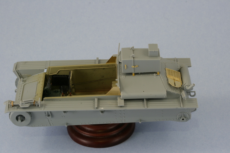
Push came to shove today and it was necessary to break out the airbrush and work on the interior. To prep for that, I masked off the already painted areas of the lower hull interior and also prepped the superstructure front and the rear panels by attaching them to strips of masking tape for easier handling.
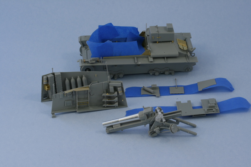
I primed everything first with a coat of Italian Dark Brown. This insured I didn't leave any bare plastic behind and once it had dried, I sprayed the base coat of 50/50 Dunkelgelb/Light Gray to all the areas of the interior. In order to make it possible to fit the tools and not worry about masking them, I went ahead and painted the full lengths of the fenders as well as the engine deck and rear hull panel. These areas are much more accessible now vs. when the superstructure is fitted, so I took full advantage of the situation. The photo below shows the dunkelgelb as being a little darker than it actually is, I just didn't play around with the lighting too much when taking this shot and didn't notice it until later.
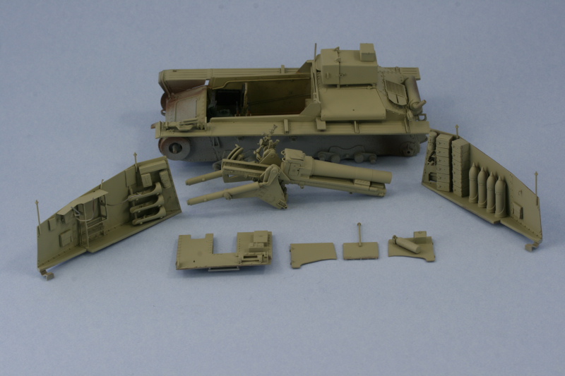
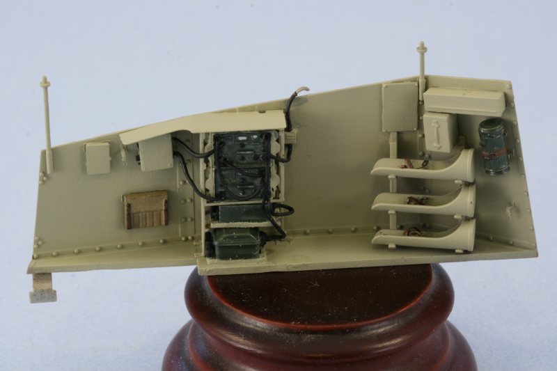
With the base coat on, it was now down to the detail work. I started in on the left hand side first since it had the most to do. The radios and gear were painted using a 50-50 mix of Panzer Gray and Russian Armor Green to create a sort of field-gray color and then installed into their racks. The fit is tight so only a small amount of glue was needed. The next step was to complete all of the wiring using the lengths of solder I'd added earlier plus several other lengths that needed to be cut to size and installed. I used the wiring diagram for the Marder II radio sets in Achtung Panzer #7 as a guide since it's essentially the same radio setup here in the Grille H with just a couple of minor differences. I also detailed the MP40 ammunition pouches and the belts in the empty ammunition racks on this side along with the gas mask container.
The side's not finished yet, I still need to add in the MP40 along with the gunner's seat cushion and do some weathering before it's ready for installation.
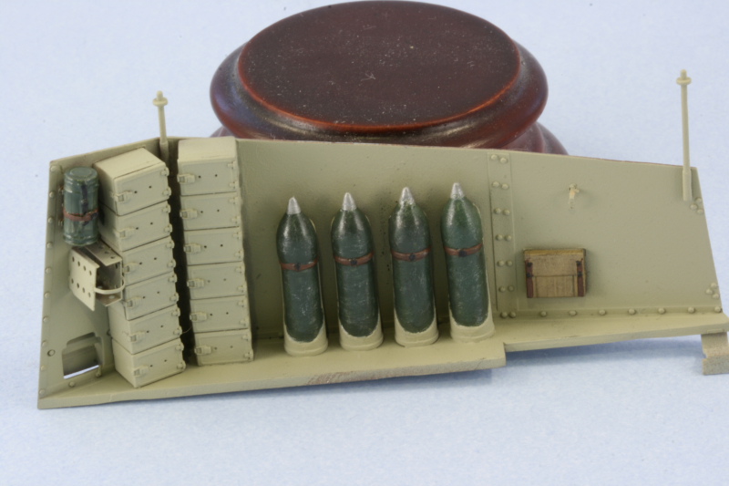
The right hand side was next and I quickly discovered the limitations of trying to paint the 4 15cm rounds while installed. I think it would've been a lot easier had I painted them off the vehicle and installed but rather than pull them out, I went ahead and painted them in location. I used the same 50-50 Panzer Gray/Russian Armor Green mix for the shell bodies and dry brushed some Steel, counter-dry brushed Russian Armor Green, and then ended with a dusting of black artist pastels. As with the opposite side, I still need to add the MP40, seat cushion, and weathering to complete this side.
The devil's always in the details and this part of the build is no exception.
Total Session Time: 5.5 hours
Total Time to Date: 38.25 hours
I primed everything first with a coat of Italian Dark Brown. This insured I didn't leave any bare plastic behind and once it had dried, I sprayed the base coat of 50/50 Dunkelgelb/Light Gray to all the areas of the interior. In order to make it possible to fit the tools and not worry about masking them, I went ahead and painted the full lengths of the fenders as well as the engine deck and rear hull panel. These areas are much more accessible now vs. when the superstructure is fitted, so I took full advantage of the situation. The photo below shows the dunkelgelb as being a little darker than it actually is, I just didn't play around with the lighting too much when taking this shot and didn't notice it until later.
With the base coat on, it was now down to the detail work. I started in on the left hand side first since it had the most to do. The radios and gear were painted using a 50-50 mix of Panzer Gray and Russian Armor Green to create a sort of field-gray color and then installed into their racks. The fit is tight so only a small amount of glue was needed. The next step was to complete all of the wiring using the lengths of solder I'd added earlier plus several other lengths that needed to be cut to size and installed. I used the wiring diagram for the Marder II radio sets in Achtung Panzer #7 as a guide since it's essentially the same radio setup here in the Grille H with just a couple of minor differences. I also detailed the MP40 ammunition pouches and the belts in the empty ammunition racks on this side along with the gas mask container.
The side's not finished yet, I still need to add in the MP40 along with the gunner's seat cushion and do some weathering before it's ready for installation.
The right hand side was next and I quickly discovered the limitations of trying to paint the 4 15cm rounds while installed. I think it would've been a lot easier had I painted them off the vehicle and installed but rather than pull them out, I went ahead and painted them in location. I used the same 50-50 Panzer Gray/Russian Armor Green mix for the shell bodies and dry brushed some Steel, counter-dry brushed Russian Armor Green, and then ended with a dusting of black artist pastels. As with the opposite side, I still need to add the MP40, seat cushion, and weathering to complete this side.
The devil's always in the details and this part of the build is no exception.
Total Session Time: 5.5 hours
Total Time to Date: 38.25 hours