
Tamiya Marder III Sdkfz 139 7.62cm Pak36(r) (2009)
-
Bill Plunk
- Posts: 1245
- Joined: Wed Sep 28, 2022 10:18 pm
Tamiya Marder III Sdkfz 139 7.62cm Pak36(r) (2009)
Build Log for Tamiya Marder III kit with Eduard PE, Jordi Rubio aluminum barrel, Eduard PE, Verlinden resin interior, LionMarc hull machine gun, and Model Kasten workable tracks. Not pictured but also to be included is Tristar's Pz 38t Interior.
-
Bill Plunk
- Posts: 1245
- Joined: Wed Sep 28, 2022 10:18 pm
WIP 01-25-2009
Another weekend means another project! This particular project is one that has been waiting quietly for some time in the background and its turn finally came. I will be building Tamiya's Marder III kit #35248 with a variety of aftermarket goodies including Tristar's Pz 38t Interior once it arrives...and the fact that it hasn't arrived yet is going to make the build order for this one a little unorthodox!
Since I'm intending to use elements from both the Verlinden and the Tristar interior set, I can't start on that until I have both on hand and can see how they will interact with each other. This means that I can't build up the lower hull tub yet or do anything with the lower hull or suspension for that matter. The only area I can safely work on at the moment is the gun, so I skipped ahead to Step 18 in the instructions and started work there.
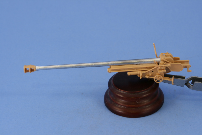
My first order of business was to work with the gun itself. Step 18 directs the assembly of the two-part gun barrel and its attachment to the breech block and recoil tray. Since I was replacing the barrel with the JR aluminum barrel, this step was heavily modified. The breech part already had an opening to take the base of the Tamiya barrel but its diameter was too large vs. the mount pin on the base of the JR barrel. To resolve this, I used some Aves Apoxysculpt two-part putty and packed that into the base. Some CA gel was then used to secure it firmly in place and CA gel used to glue the barrel to the recoil sled.
Another challenge immediately presented itself in the form of the JR white metal muzzle brake being totally inaccurate. Compared to scale drawings in Nuts & Bolts #15 and the kit parts, it proved to be undersized in every way and looks more like a Pak 40 brake than the brake used on the re-chambered Russian 7.62cm Pak 36(r). To resolve this, I went ahead and glued the two halves of the kit supplied barrel together at the front and let it dry, then used a razor saw to remove the brake portion. The brake was carefully trimmed and sanded until it matched to the barrel. Because I needed some working time with the alignment, I used Gator Grip glue instead of CA and set it off to the side to dry overnight.

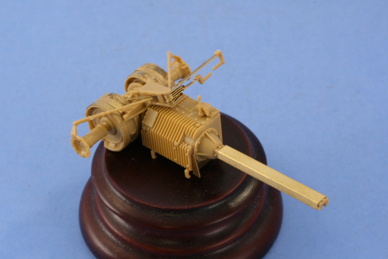
The other half of Step 18 calls for the assembly of the gun mount and tray. The tray is a two-part assembly and it required some attention in terms of removing some ejector marks that would be visible inside the tray and dealing with the seam down the middle. I used liquid glue and careful sanding to remove most of the seam but a small amount of putty was also needed towards the end to get a smooth finish. The original kit barrel had a rectangular tab that was supposed to fit/lock into the grooves in the front of the tray but I discovered that wasn't needed so long as you glue down the recoil sled and don't need the gun to recoil.

Steps 19 and 20 just demonstrate how to insert and remove the barrel using the locking tab and don't have any construction associated with it, so it was on to Step 21. This assembles the gun sight and the sides of the gun mount proper. The gun sight was molded solid so I used a pin vise and drill bit to hollow out both the eye piece and the scope end. For the eye piece, I drilled out the hole then used a #11 blade tip and a round needle file to open it up a bit more.

For the sides of the mount, I installed everything except the elevation and traverse hand wheels. These were left separate until the halves were assembled to avoid damaging them in the process.

That assembly is accomplished in Step 22 and the instructions direct you to be careful with the glue to allow the gun tray to elevate once the installation is complete. The right side fits tightly onto a pin and the left side is trapped over a small raised circular point on the gun tray, so it's very solid.

Step 23 adds some very important details for the equilibrator since these will be visible depending on the elevation of the gun and the way it's mounted to the vehicle. The fit here is very precise, the elevation gear on the tray appears to make contact with the gear underneath but actually has just enough clearance to elevate on its own without actually making contact.

Before proceeding on, it's important to note here that the Tamiya instructions contain a very serious error in Step 24 that will cause a lot of grief if you haven't looked ahead...this step directs the installation and attachment of the front gun shield and the final installation of the barrel and recoil sled isn't called for until Step 26...however you won't be able to make this work due to the installation of the sliding splinter shield in Step 24 that's necessary to complete the front gun shield as it won't provide sufficient clearance for the muzzle brake to fit through!
As a result, I went ahead and glued the recoil sled down into the proper position on the mount tray with liquid glue.
With disaster averted, I started work on the gun shield. Step 24 deals with only the front portion while Step 25 deals with the sides. In order to facilitate painting and detailing, I've decided to leave the gun shield separate from the gun itself but that meant I needed to install some things and test out their fit to be sure everything would in fact align properly. Before getting to that, some shallow ejector marks needed to be sanded down and carefully removed from both the front and sides. There was also one mark on the sliding splinter shield that was too deep and needed some putty work to deal with it. Details from the Eduard set were added for the clasps on the various storage boxes/containers and the holders for the gas masks. The mount pins for the gas masks were carefully removed and sanded down and the holders installed with CA gel to make sure they stay put as they will undergo a lot of handling before it's all said and done.
The periscopes were added for both the front and side panels and it's important not to mix these up. Since the front panel sits at an angle, the periscopes also have to be installed at an angle so that they will be straight/vertical once the plate is installed. The Eduard set included parts to replace these mounts but after comparing them to the Nuts & Bolts pics and the way the kit mounts are designed, they weren't going to be practical or particularly accurate, so they weren't used.

In order to get the right alignment between the front and side panels, I started with the left side first and used regular glue to attach the side to the front. I followed up with liquid glue around the edges and interior to make sure a solid join was present, then dry-fit it to the gun mount. Everything worked, so the process was repeated with the right side. the right side wanted to bow out slightly, so I used some finger pressure and also added the top canvas support bar to provide an additional contact point to bring it back into alignment. I debated about gluing the shield down onto the supports at this stage but elected to still go ahead with my plans to leave them separate as the working space is pretty tight for hand painting, never mind airbrush work.

I let the shields set up dry-fit so that it would keep its shape and after about an hour so, removed it. The final element came in Step 26 with the addition of the small semi-circular front plates. These are marked D36 and D35 on their undersides to insure you get them in the right place and I carefully removed those markings with a knife point so they wouldn't be visible after installation.

While I wait for the Tristar interior to come in I will work on the MK tracks so as not to lose too much time in the process.
Since I'm intending to use elements from both the Verlinden and the Tristar interior set, I can't start on that until I have both on hand and can see how they will interact with each other. This means that I can't build up the lower hull tub yet or do anything with the lower hull or suspension for that matter. The only area I can safely work on at the moment is the gun, so I skipped ahead to Step 18 in the instructions and started work there.
My first order of business was to work with the gun itself. Step 18 directs the assembly of the two-part gun barrel and its attachment to the breech block and recoil tray. Since I was replacing the barrel with the JR aluminum barrel, this step was heavily modified. The breech part already had an opening to take the base of the Tamiya barrel but its diameter was too large vs. the mount pin on the base of the JR barrel. To resolve this, I used some Aves Apoxysculpt two-part putty and packed that into the base. Some CA gel was then used to secure it firmly in place and CA gel used to glue the barrel to the recoil sled.
Another challenge immediately presented itself in the form of the JR white metal muzzle brake being totally inaccurate. Compared to scale drawings in Nuts & Bolts #15 and the kit parts, it proved to be undersized in every way and looks more like a Pak 40 brake than the brake used on the re-chambered Russian 7.62cm Pak 36(r). To resolve this, I went ahead and glued the two halves of the kit supplied barrel together at the front and let it dry, then used a razor saw to remove the brake portion. The brake was carefully trimmed and sanded until it matched to the barrel. Because I needed some working time with the alignment, I used Gator Grip glue instead of CA and set it off to the side to dry overnight.
The other half of Step 18 calls for the assembly of the gun mount and tray. The tray is a two-part assembly and it required some attention in terms of removing some ejector marks that would be visible inside the tray and dealing with the seam down the middle. I used liquid glue and careful sanding to remove most of the seam but a small amount of putty was also needed towards the end to get a smooth finish. The original kit barrel had a rectangular tab that was supposed to fit/lock into the grooves in the front of the tray but I discovered that wasn't needed so long as you glue down the recoil sled and don't need the gun to recoil.
Steps 19 and 20 just demonstrate how to insert and remove the barrel using the locking tab and don't have any construction associated with it, so it was on to Step 21. This assembles the gun sight and the sides of the gun mount proper. The gun sight was molded solid so I used a pin vise and drill bit to hollow out both the eye piece and the scope end. For the eye piece, I drilled out the hole then used a #11 blade tip and a round needle file to open it up a bit more.
For the sides of the mount, I installed everything except the elevation and traverse hand wheels. These were left separate until the halves were assembled to avoid damaging them in the process.
That assembly is accomplished in Step 22 and the instructions direct you to be careful with the glue to allow the gun tray to elevate once the installation is complete. The right side fits tightly onto a pin and the left side is trapped over a small raised circular point on the gun tray, so it's very solid.
Step 23 adds some very important details for the equilibrator since these will be visible depending on the elevation of the gun and the way it's mounted to the vehicle. The fit here is very precise, the elevation gear on the tray appears to make contact with the gear underneath but actually has just enough clearance to elevate on its own without actually making contact.
Before proceeding on, it's important to note here that the Tamiya instructions contain a very serious error in Step 24 that will cause a lot of grief if you haven't looked ahead...this step directs the installation and attachment of the front gun shield and the final installation of the barrel and recoil sled isn't called for until Step 26...however you won't be able to make this work due to the installation of the sliding splinter shield in Step 24 that's necessary to complete the front gun shield as it won't provide sufficient clearance for the muzzle brake to fit through!
As a result, I went ahead and glued the recoil sled down into the proper position on the mount tray with liquid glue.
With disaster averted, I started work on the gun shield. Step 24 deals with only the front portion while Step 25 deals with the sides. In order to facilitate painting and detailing, I've decided to leave the gun shield separate from the gun itself but that meant I needed to install some things and test out their fit to be sure everything would in fact align properly. Before getting to that, some shallow ejector marks needed to be sanded down and carefully removed from both the front and sides. There was also one mark on the sliding splinter shield that was too deep and needed some putty work to deal with it. Details from the Eduard set were added for the clasps on the various storage boxes/containers and the holders for the gas masks. The mount pins for the gas masks were carefully removed and sanded down and the holders installed with CA gel to make sure they stay put as they will undergo a lot of handling before it's all said and done.
The periscopes were added for both the front and side panels and it's important not to mix these up. Since the front panel sits at an angle, the periscopes also have to be installed at an angle so that they will be straight/vertical once the plate is installed. The Eduard set included parts to replace these mounts but after comparing them to the Nuts & Bolts pics and the way the kit mounts are designed, they weren't going to be practical or particularly accurate, so they weren't used.
In order to get the right alignment between the front and side panels, I started with the left side first and used regular glue to attach the side to the front. I followed up with liquid glue around the edges and interior to make sure a solid join was present, then dry-fit it to the gun mount. Everything worked, so the process was repeated with the right side. the right side wanted to bow out slightly, so I used some finger pressure and also added the top canvas support bar to provide an additional contact point to bring it back into alignment. I debated about gluing the shield down onto the supports at this stage but elected to still go ahead with my plans to leave them separate as the working space is pretty tight for hand painting, never mind airbrush work.
I let the shields set up dry-fit so that it would keep its shape and after about an hour so, removed it. The final element came in Step 26 with the addition of the small semi-circular front plates. These are marked D36 and D35 on their undersides to insure you get them in the right place and I carefully removed those markings with a knife point so they wouldn't be visible after installation.
While I wait for the Tristar interior to come in I will work on the MK tracks so as not to lose too much time in the process.
-
Bill Plunk
- Posts: 1245
- Joined: Wed Sep 28, 2022 10:18 pm
WIP 02-01-2009
I was very fortunate in that the Tristar interior set that I'd ordered came in on Friday, just in time for some weekend building! The set is a pretty impressive one with over 140 styrene and over 70 PE parts, so plenty to keep you busy!
Before I dug into that though, I needed to decide what elements from the Verlinden set to use. These were then given a good soaking in soapy water to remove their mold-release agent and set off to the side to dry. Initially I determined that I would use only the front superstructure plate, the side panels for the lower hull, the Pak 40 ammo bins, and the rear bulkhead. I ultimately would decide not to use the Verlinden bulkhead but more on that in a separate update. Because the Verlinden interior is designed for both the Marder III and Pz 38t vehicles, the right side panel had a fire extinguisher molded in that had to be removed to allow the Marder ammo bins to fit on that side. I removed it carefully with both sprue cutters and knife trimming, then sanded it down. The openings for the hull MG and the radio operator's view port had some small film that needed to be removed with a knife point as did the armored air vent on the radio operator's hull side. Casting blocks were removed using a razor saw and then carefully trimmed down with a #11 blade and carefully sanded.

While the parts were drying, I went to work on the 1st step in the Tristar interior instructions and it's quite a busy step. A pic is worth 1000 words, so here's the step diagram to give you an idea.

The strips for the brake drums required annealing in order to get them to fit properly, I accomplished this by carefully heating the parts in my kitchen gas burner with locking tweezers...just a second or two in the flame is all that was needed. They were then glued into place one end at a time with CA gel then wrapped and secured with the other end. The steering lever assembly was an exercise in patience...essentially all the parts stack on top of each other but you have to do it upside down as the pin that holds them is on the top piece vs. the bottom...why they designed it that way I don't know. The pin isn't quite long enough to hold all the pieces either, so the last 3 you have to fit by eye to keep everything lined up properly. I assembled all the levers first and then added the little connecting arms as trying to do that first is nearly impossible as they are very very delicate (and tiny!).

The lower hull is assembled as a series of panels, so in order to be sure that everything would play nice together, I went ahead and installed the Verlinden panels to the Tamiya hull sides. The Tamiya panels had an angular molded in bar that had to be completely removed to allow the panels to fit on both sides. The Verlinden pieces fit almost exactly to the Tamiya parts with just a little bit off on the lower edge on one piece. Both panels were glued in place with CA gel. Initial test fits with the hull floor and the Tristar elements showed that I needed to trim down some of the molded on detail above the side pad for the driver to allow proper clearance for the steering levers when they were installed. From this point on everything requires LOTS of test-fits, test-fits, and more test-fits to avoid problems as tolerances are very tight all around.

With that taken care of, the next part of the step was to assemble the transmission and its stand. These parts went together very smoothly and is ultimately why I decided to go with the Tristar bulkhead instead of the resin Verlinden bulkhead. The Verlinden bulkhead is very thick and the included drive shaft is too short, so the Tristar parts will be used instead. The drive shaft was installed to the transmission and the transmission added to the brake housings. The PE leather cover was also added as it will be the foundation on which the radio rack is installed when the time comes and I needed everything solid here for fitting purposes.
Next were the details for the hull floor itself. The driver's gas and brake pedals were added without any real modifications required for them to fit. The cross bar that the transmission mounts too as well as the seats from the Tristar set had to be trimmed to allow for clearance of the Verlinden panels and the molded on bar in the Tamiya kit carefully removed and sanded down since it was in the wrong place by about 2mm. The ejector marks in the floor was filled with Squadron White putty and sanded smooth. After careful test fitting with the Tristar bulkhead and the side panels, the PE insert representing the wooden floor covering was installed using liquid glue which was carefully flooded over the PE plate so that it would take advantage of the large surface area but not mar the PE details appearance in the process. The crew seats from the Tristar set were assembled, these are highly detailed items with the ratchet mechanisms for the seat adjustment represented with multiple PE parts and separate top and bottom seat cushions. I left the cushions separate for now to facilitate painting but the seats themselves were installed. Their placement had to be precise, so a lot of test fitting with the transmission/brakes and side panels was called for.


The transmission and brake housings are just dry fit for now. I still need to work on the radio racks and the transformers before this area is done. The bulkhead also needs some detail work before it's ready to go, so next weekend will see continued emphasis on the interior and possibly some painting!
Before I dug into that though, I needed to decide what elements from the Verlinden set to use. These were then given a good soaking in soapy water to remove their mold-release agent and set off to the side to dry. Initially I determined that I would use only the front superstructure plate, the side panels for the lower hull, the Pak 40 ammo bins, and the rear bulkhead. I ultimately would decide not to use the Verlinden bulkhead but more on that in a separate update. Because the Verlinden interior is designed for both the Marder III and Pz 38t vehicles, the right side panel had a fire extinguisher molded in that had to be removed to allow the Marder ammo bins to fit on that side. I removed it carefully with both sprue cutters and knife trimming, then sanded it down. The openings for the hull MG and the radio operator's view port had some small film that needed to be removed with a knife point as did the armored air vent on the radio operator's hull side. Casting blocks were removed using a razor saw and then carefully trimmed down with a #11 blade and carefully sanded.
While the parts were drying, I went to work on the 1st step in the Tristar interior instructions and it's quite a busy step. A pic is worth 1000 words, so here's the step diagram to give you an idea.
The strips for the brake drums required annealing in order to get them to fit properly, I accomplished this by carefully heating the parts in my kitchen gas burner with locking tweezers...just a second or two in the flame is all that was needed. They were then glued into place one end at a time with CA gel then wrapped and secured with the other end. The steering lever assembly was an exercise in patience...essentially all the parts stack on top of each other but you have to do it upside down as the pin that holds them is on the top piece vs. the bottom...why they designed it that way I don't know. The pin isn't quite long enough to hold all the pieces either, so the last 3 you have to fit by eye to keep everything lined up properly. I assembled all the levers first and then added the little connecting arms as trying to do that first is nearly impossible as they are very very delicate (and tiny!).
The lower hull is assembled as a series of panels, so in order to be sure that everything would play nice together, I went ahead and installed the Verlinden panels to the Tamiya hull sides. The Tamiya panels had an angular molded in bar that had to be completely removed to allow the panels to fit on both sides. The Verlinden pieces fit almost exactly to the Tamiya parts with just a little bit off on the lower edge on one piece. Both panels were glued in place with CA gel. Initial test fits with the hull floor and the Tristar elements showed that I needed to trim down some of the molded on detail above the side pad for the driver to allow proper clearance for the steering levers when they were installed. From this point on everything requires LOTS of test-fits, test-fits, and more test-fits to avoid problems as tolerances are very tight all around.
With that taken care of, the next part of the step was to assemble the transmission and its stand. These parts went together very smoothly and is ultimately why I decided to go with the Tristar bulkhead instead of the resin Verlinden bulkhead. The Verlinden bulkhead is very thick and the included drive shaft is too short, so the Tristar parts will be used instead. The drive shaft was installed to the transmission and the transmission added to the brake housings. The PE leather cover was also added as it will be the foundation on which the radio rack is installed when the time comes and I needed everything solid here for fitting purposes.
Next were the details for the hull floor itself. The driver's gas and brake pedals were added without any real modifications required for them to fit. The cross bar that the transmission mounts too as well as the seats from the Tristar set had to be trimmed to allow for clearance of the Verlinden panels and the molded on bar in the Tamiya kit carefully removed and sanded down since it was in the wrong place by about 2mm. The ejector marks in the floor was filled with Squadron White putty and sanded smooth. After careful test fitting with the Tristar bulkhead and the side panels, the PE insert representing the wooden floor covering was installed using liquid glue which was carefully flooded over the PE plate so that it would take advantage of the large surface area but not mar the PE details appearance in the process. The crew seats from the Tristar set were assembled, these are highly detailed items with the ratchet mechanisms for the seat adjustment represented with multiple PE parts and separate top and bottom seat cushions. I left the cushions separate for now to facilitate painting but the seats themselves were installed. Their placement had to be precise, so a lot of test fitting with the transmission/brakes and side panels was called for.
The transmission and brake housings are just dry fit for now. I still need to work on the radio racks and the transformers before this area is done. The bulkhead also needs some detail work before it's ready to go, so next weekend will see continued emphasis on the interior and possibly some painting!
-
Bill Plunk
- Posts: 1245
- Joined: Wed Sep 28, 2022 10:18 pm
WIP 02-06-2009
I've been making some slow progress here and there working on some of the remaining items during the week in anticipation of being able to paint the interior this weekend. The remaining items were the radios and their transformers as well as the details for the rear bulkhead.
Pics of the interior of 38ts are hard to come by and the interior shots shown in Panzer Tracts #18 are from a field manual that doesn't show the radios fitted in a Slovak LT38...so they weren't much help. The Nuts & Bolts #15 however has a couple of shots that helped and there were really all I had to go on. The Tristar interior set instructions are extremely unhelpful in the placement of the radios with no diagram for them whatsoever and only a very vague placement instruction for the transformer/battery tray.


After studying those two (plus one more that shows the underside of the drive shaft housing on the rear bulkhead) and looking at the instructions inside the Tristar Marder III H was I finally able to figure it out. The radio rack mounts directly to the drive shaft and is held in place by two small sheet metal brackets on either end. The transformer tray installs directly to the floor underneath the drive shaft.
With that out of the way, I now had my way forward and assembled the transformer/battery packs as well as the radio transmitter and receiver. I prepped these with a micro-drill in a pin vise to create some mount holes for 0.5mm solder wiring that will get installed after painting.

The Tristar radio racks aren't quite accurate for the Marder either as the racks are individual for each radio instead of one single rack with a divider, but these are close enough for my purposes. The side mounts are those designed to attach a vertical surface vs. the horizontal, so these were modified by trimming down with sharp side cutters to get it to the size and position needed. The radios can easily slide in and out, so I left them separate to make it easier to paint/detail and wire them up. The racks where then glued directly to the drive shaft cover with CA gel.

With the racks in place, it was possible to determine where to install the transformer/battery rack. The transformers were glued into the rack and then the rack installed to the hull floor. There's just enough clearance for everything and it demonstrates just how tight/packed the interior was on these vehicles.

The last item was the rear bulkhead separating the fighting compartment from the engine compartment. The bulkhead received the engine cap that has the drive shaft connection and the PE heating vent slides were installed in the closed position and the PE screen and wrench tool added to round things out.

The interior is now ready for paint. The transmission/brakes/drive shaft is only dry-fit for now and will be painted as a separate module. Lots of fun still ahead!

Pics of the interior of 38ts are hard to come by and the interior shots shown in Panzer Tracts #18 are from a field manual that doesn't show the radios fitted in a Slovak LT38...so they weren't much help. The Nuts & Bolts #15 however has a couple of shots that helped and there were really all I had to go on. The Tristar interior set instructions are extremely unhelpful in the placement of the radios with no diagram for them whatsoever and only a very vague placement instruction for the transformer/battery tray.
After studying those two (plus one more that shows the underside of the drive shaft housing on the rear bulkhead) and looking at the instructions inside the Tristar Marder III H was I finally able to figure it out. The radio rack mounts directly to the drive shaft and is held in place by two small sheet metal brackets on either end. The transformer tray installs directly to the floor underneath the drive shaft.
With that out of the way, I now had my way forward and assembled the transformer/battery packs as well as the radio transmitter and receiver. I prepped these with a micro-drill in a pin vise to create some mount holes for 0.5mm solder wiring that will get installed after painting.
The Tristar radio racks aren't quite accurate for the Marder either as the racks are individual for each radio instead of one single rack with a divider, but these are close enough for my purposes. The side mounts are those designed to attach a vertical surface vs. the horizontal, so these were modified by trimming down with sharp side cutters to get it to the size and position needed. The radios can easily slide in and out, so I left them separate to make it easier to paint/detail and wire them up. The racks where then glued directly to the drive shaft cover with CA gel.
With the racks in place, it was possible to determine where to install the transformer/battery rack. The transformers were glued into the rack and then the rack installed to the hull floor. There's just enough clearance for everything and it demonstrates just how tight/packed the interior was on these vehicles.
The last item was the rear bulkhead separating the fighting compartment from the engine compartment. The bulkhead received the engine cap that has the drive shaft connection and the PE heating vent slides were installed in the closed position and the PE screen and wrench tool added to round things out.
The interior is now ready for paint. The transmission/brakes/drive shaft is only dry-fit for now and will be painted as a separate module. Lots of fun still ahead!
-
Bill Plunk
- Posts: 1245
- Joined: Wed Sep 28, 2022 10:18 pm
WIP 02-07-2009
I thought I was all ready for paint but had overlooked the superstructure front plate that houses the hull MG and the driver and radio operator view ports. The Verlinden set includes a very nice panel that inserts to the Tamiya plate and also provides a replacement rear half of the MG but requires some pretty hefty surgery to mate it up to the Tamiya MG to be workable. Instead of doing all that, I pirated the spare from a Tristar Marder III H kit (it has two but only one is needed) because it has the correct detail on the outer ball face whereas the Tamiya part was smooth and missing the targeting scope port and the direct fire peep hole. Only minor surgery was necessary to the Tamiya part to remove a small nub that interfered and some CA gel secured the Verlinden interior detail plate with no problem. I did discover however that some trimming on the left hull side interior plate was necessary since the open view flap needed some clearance, so good thing I hadn't started painting yet!
The Tristar ball mount has the gun and support tray separate which makes it much easier to fit the Lion Marc replacement barrel and tray. The Lion Marc barrel has a small mount pin but it's too small in diameter vs. the opening in the Tristar part, so the pin was removed with side cutters and the nub carefully ground down with my Dremel Mighty Mite and then glued in place with CA gel. The tray was then glued to the barrel and the delicate little gun sight left off until later to avoid losing it from all the handling that it will have to go through before final installation.
The final little detail was the installation of some type of cable that attaches to the rear end of the MG and then connects up to the transmission housing...possibly a power cord? This was added by drilling a small hole with the pin vise and then gluing in place a length of 0.5mm solder that was bent to the necessary shape. I also used the Verlinden sighting scope and glued it into position with CA gel since it had better detail than the part in the Tristar Marder III H kit as that part is also a little undersized.

With that taken care of, I used the airbrush to paint all of the interior panels with Testors enamel Panzer Interior Buff since that's their version of elfenbein. The radios, transformer/battery pack, and the transmission/brakes were airbrushed with Russian Armor Green. Once that had dried, I went to work on the details. The radios were detailed using the magnifier and Aircraft Interior Black for their dials and knobs and Light Gray for the display faces. The 0.5mm solder wiring was added to connect up the receiver and transmitter as well as to the battery/transformers and the wiring was also painted with Aircraft Interior Black. The long wire to connect the antenna on the hull exterior was also added at this point...it took a lot of careful study with the exterior panels as well as some reference photos to determine the best way to handle it. I decided to install a long length of solder that can be bent and trimmed to connect to the base of the antenna mount when the time comes vs. trying to install it later when all the superstructure parts were in place.
The lower floor was weathered first with some dry-brushed Raw Umber to create scuffs and scrapes and then some dirt/mud accumulation added using Mig Europe Dust applied as a dry powder and scrubbed into various corners. This was fixed in position using both dry and wet Q-tips to buff and blend it into the paint. The seat cushions were painted using thinned down Aircraft Interior Black to allow the very finely molded leather pattern to show through just a bit to round things out and the transmission/brake housing glued into a fixed position. The transmission was weathered by applying a thin wash of black followed by a very light dry-brushing of Steel to the cooling fins and bolts.

The rest of the panels were weathered next by dry-brushing some Raw Umber to create scuffs and nicks here and there and then a pin wash of Raw Umber applied carefully since the surface was unsealed. Some of the Panzer Interior Buff was then dry brushed to blend things back in. The MG and scope were painted and detailed with Metalizer Non-Buffing Gunmetal and then dry-brushed with Steel. The little signal lights for the driver were painted with Tamiya Clear Red, Green, and Green + Yellow (I didn't have Blue!) and the driver's armored glass viewport simulated with a base coat of Silver and Tamiya Clear Smoke over that.

Finally, the moment of truth had arrived! It was time to construct the lower hull following the Tamiya instructions for Step 1...the front armor was added first, then the left side, followed by the right, and the rear panel added last. To help square things up, I then added the interior bulkhead and the glacis plate. The glacis plate required a rubber band to get the front sides to close up properly, so this will be left on overnight to allow it to thoroughly set. I also dry-fit the superstructure front plate to make sure everything was sitting properly. The Eduard set included a short ammo belt for the MG, so I added that and painted the shell casings with Metalizer Brass to round things out.

Because of the way the superstructure plate interacts with the fenders and the upper portion of the fighting compartment, it's not going to be installed just yet. The hull will set up overnight and next will be the suspension and other exterior details to keep this one moving along.

A few more detail shots with better lighting and after the rubber band had been removed from the front hull.


The Tristar ball mount has the gun and support tray separate which makes it much easier to fit the Lion Marc replacement barrel and tray. The Lion Marc barrel has a small mount pin but it's too small in diameter vs. the opening in the Tristar part, so the pin was removed with side cutters and the nub carefully ground down with my Dremel Mighty Mite and then glued in place with CA gel. The tray was then glued to the barrel and the delicate little gun sight left off until later to avoid losing it from all the handling that it will have to go through before final installation.
The final little detail was the installation of some type of cable that attaches to the rear end of the MG and then connects up to the transmission housing...possibly a power cord? This was added by drilling a small hole with the pin vise and then gluing in place a length of 0.5mm solder that was bent to the necessary shape. I also used the Verlinden sighting scope and glued it into position with CA gel since it had better detail than the part in the Tristar Marder III H kit as that part is also a little undersized.
With that taken care of, I used the airbrush to paint all of the interior panels with Testors enamel Panzer Interior Buff since that's their version of elfenbein. The radios, transformer/battery pack, and the transmission/brakes were airbrushed with Russian Armor Green. Once that had dried, I went to work on the details. The radios were detailed using the magnifier and Aircraft Interior Black for their dials and knobs and Light Gray for the display faces. The 0.5mm solder wiring was added to connect up the receiver and transmitter as well as to the battery/transformers and the wiring was also painted with Aircraft Interior Black. The long wire to connect the antenna on the hull exterior was also added at this point...it took a lot of careful study with the exterior panels as well as some reference photos to determine the best way to handle it. I decided to install a long length of solder that can be bent and trimmed to connect to the base of the antenna mount when the time comes vs. trying to install it later when all the superstructure parts were in place.
The lower floor was weathered first with some dry-brushed Raw Umber to create scuffs and scrapes and then some dirt/mud accumulation added using Mig Europe Dust applied as a dry powder and scrubbed into various corners. This was fixed in position using both dry and wet Q-tips to buff and blend it into the paint. The seat cushions were painted using thinned down Aircraft Interior Black to allow the very finely molded leather pattern to show through just a bit to round things out and the transmission/brake housing glued into a fixed position. The transmission was weathered by applying a thin wash of black followed by a very light dry-brushing of Steel to the cooling fins and bolts.
The rest of the panels were weathered next by dry-brushing some Raw Umber to create scuffs and nicks here and there and then a pin wash of Raw Umber applied carefully since the surface was unsealed. Some of the Panzer Interior Buff was then dry brushed to blend things back in. The MG and scope were painted and detailed with Metalizer Non-Buffing Gunmetal and then dry-brushed with Steel. The little signal lights for the driver were painted with Tamiya Clear Red, Green, and Green + Yellow (I didn't have Blue!) and the driver's armored glass viewport simulated with a base coat of Silver and Tamiya Clear Smoke over that.
Finally, the moment of truth had arrived! It was time to construct the lower hull following the Tamiya instructions for Step 1...the front armor was added first, then the left side, followed by the right, and the rear panel added last. To help square things up, I then added the interior bulkhead and the glacis plate. The glacis plate required a rubber band to get the front sides to close up properly, so this will be left on overnight to allow it to thoroughly set. I also dry-fit the superstructure front plate to make sure everything was sitting properly. The Eduard set included a short ammo belt for the MG, so I added that and painted the shell casings with Metalizer Brass to round things out.
Because of the way the superstructure plate interacts with the fenders and the upper portion of the fighting compartment, it's not going to be installed just yet. The hull will set up overnight and next will be the suspension and other exterior details to keep this one moving along.
A few more detail shots with better lighting and after the rubber band had been removed from the front hull.
-
Bill Plunk
- Posts: 1245
- Joined: Wed Sep 28, 2022 10:18 pm
WIP 02-08-2009
With the interior out of the way, it was time to return to the "normal" order of construction more or less. I picked up with Step 2 and attached the suspension elements to both sides. In order to fit the Model Kasten sprocket adapter, I removed the fixed mount pin from the hull side and installed the adapter inside the final drive cover. The adapter can rotate freely inside the mount allowing the sprocket in turn to rotate when mounted which will be very helpful when it comes time to mount the MK tracks. The fixed idler mount was removed with sprue cutters and carefully sanded down and then the mount hole drilled out with the Dremel to take the movable MK idler mount which will allow the idler to be adjusted for proper track tension.

To be sure that the suspension elements were sitting properly and the vehicle was level, I removed all the road wheels and cleaned up their mold seam with a sanding twig. After some small tweaks, the wheels were removed and the hull set off to the side to let the suspension set up. I also assembled the MK sprockets and idlers and cleaned up the return rollers.

Step 3 calls for the installation of the superstructure plate and the fenders, but before I did that I went ahead and installed the mounts for the spare track holders. I learned from working on the Tristar 38t E/F that it's good to take care of this now when there's plenty of room to maneuver. Once they were in place and aligned properly, I installed the front superstructure plate.

I had originally intended to fit the Eduard PE fenders that came in the detail set but after a test installation of the front mount and one fender I discovered that the height of the fender isn't correct on the Eduard set so opted for the kit fenders instead. This meant that some of the molded on locator points for the fender gear and tools needed to be removed and some holes filled with putty on the hull side. The fender was then installed, using the Tamiya provided guide molded into the hull side to get the subtle kink in the fender. The process was repeated for the opposite side as well.


I started in on the fender PE work but only got the one side done. The mount for the sledgehammer was installed and the kit-supplied fire extinguisher had its molded on details removed and a PE makeover applied. This side gets the long cleaning rods and pry bar but they are just secured with simple straps, so I will paint and detail them first and then install the straps later. The shovel also is held in place with a strap and a small U-shaped retainer for the handle, the retainer was added to the hull side.

Once the hull top/fighting compartment floor is added the areas get pretty tight. I'm going to have to see how things look like on the other side and may have to do some pre-painting on the exterior in order to get everything covered. Won't be able to determine that until next weekend though.
To be sure that the suspension elements were sitting properly and the vehicle was level, I removed all the road wheels and cleaned up their mold seam with a sanding twig. After some small tweaks, the wheels were removed and the hull set off to the side to let the suspension set up. I also assembled the MK sprockets and idlers and cleaned up the return rollers.
Step 3 calls for the installation of the superstructure plate and the fenders, but before I did that I went ahead and installed the mounts for the spare track holders. I learned from working on the Tristar 38t E/F that it's good to take care of this now when there's plenty of room to maneuver. Once they were in place and aligned properly, I installed the front superstructure plate.
I had originally intended to fit the Eduard PE fenders that came in the detail set but after a test installation of the front mount and one fender I discovered that the height of the fender isn't correct on the Eduard set so opted for the kit fenders instead. This meant that some of the molded on locator points for the fender gear and tools needed to be removed and some holes filled with putty on the hull side. The fender was then installed, using the Tamiya provided guide molded into the hull side to get the subtle kink in the fender. The process was repeated for the opposite side as well.
I started in on the fender PE work but only got the one side done. The mount for the sledgehammer was installed and the kit-supplied fire extinguisher had its molded on details removed and a PE makeover applied. This side gets the long cleaning rods and pry bar but they are just secured with simple straps, so I will paint and detail them first and then install the straps later. The shovel also is held in place with a strap and a small U-shaped retainer for the handle, the retainer was added to the hull side.
Once the hull top/fighting compartment floor is added the areas get pretty tight. I'm going to have to see how things look like on the other side and may have to do some pre-painting on the exterior in order to get everything covered. Won't be able to determine that until next weekend though.
-
Bill Plunk
- Posts: 1245
- Joined: Wed Sep 28, 2022 10:18 pm
WIP 02-15-2009
This weekend was a very productive one and was all about the details. Picking up from where I left off last time, attention went first to the left side fender. This dealt with the items covered in Tamiya's Step 8 and involved quite a bit of replacement work using the Eduard items. The grouser box was replaced in its entirety as were the jack holders, which made for an interesting exercise since the Eduard items make the jack stand just a bit taller than the kit parts, so to get it to fit properly with the fighting compartment overhang, the handle and the foot end were sanded down ever so slightly. The tool clamps were also added for the wire cutters and the axe with the axe able to slide out for detail painting by the wire cutters are stuck in place and will have to be detailed in situ. The Eduard set calls for little retainers to be added to the wire cutter handles but there's no evidence of those being in place on the surviving Marders I have reference photos for, so I left them off. The jack block has enough room to slide in and out so I left that off to the side to allow for easier painting. Because everything is in so tight a space, lots of back and forth and constant test-fitting with the fighting compartment was essential.

Speaking of the fighting compartment, it was time for it to get its turn. Because of the nature of the work, from here on I referred to Steps 10-13 and 15 in order to get through but it's far from linear due to all the different ways things have to interact. First up were the installation of the Verlinden ammunition boxes. These are full size vs. the cut-down versions Tamiya provides and extend all the way down to the hull floor. To fit them, it was necessary to cut away the mount trays that were molded into the cross member. I cut a little too deeply on the left hand side so had to restore the small lip there with some sheet styrene. The Eduard MG ammunition boxes were also added to the underside. I have some ammo boxes from the Tristar set but will add those after painting.

Not uncommon with resin parts, the boxes needed some trimming/modification to fit properly. The molded on center ridge on the back side needed to be cut away to provide a firm gluing surfaces to the plastic cross member otherwise they were too heavy and couldn't be supported. The left side boxed came in two parts with the smallest 3-round box separate. It has to clear the drive shaft extension in the lower hull and needed to be set at an angle which required several attempts before it sat at just the right height.

Next up were the details for the ammo boxes, the Eduard set includes an excellent set of lids with separate pieces for the straps and latches. This is doubly neat since the Tamiya set only includes 8 inserts for rounds into the bins which would leave a lot of empty tubes otherwise. Applying some creative logic, I decided that the loader would likely work through the boxes on his side first, so all of the gunner/commander's side were closed up and only the 5-round bin on the loader's side left open. The small retainer clips were added using the Eduard set with small dabs of CA gel. I also added the rear portion of the gun travel lock and left it movable as called for in the instructions. The crew MP40 was installed and the barrel and empty magazine receiver drilled out to give it a more realistic appearance.

Details were also added to the front over the driver and radio operator compartments. I added the Eduard gas mask holders but left the radio operator's empty for a little variety and also to allow more of a view of the details like the radio through that little window. The straps were positioned as if they were hanging loose due to gravity. I also mistakenly installed a part on the radio operator's side thinking that I needed to mirror the driver's side, that little hooked rack actually belongs to the rear area so it was removed later on and repositioned.

Next came the moment of truth...I'd been debating on the best way to handle the fighting compartment in terms of painting and installation. After much deliberation I decided it would be best if the fighting compartment interior was painted separately and then installed and masked off where needed when the rest of the exterior would get its paint work done. I just didn't see any other way to protect the interior and be sure to get into all the little nooks and crannies. So, that meant that the side panels needed to be installed. Before I tackled that, I puttied over the incorrect mount tab on the left side for the antenna base and sanded it down. Using a combination of liquid glue and regular glue, I attached both sides first. After the glue had set a big, I dry-fit it to the lower hull and then carefully glued the front panel into position. Everything fit very tight, almost a snap-fit, so that's comforting at least. Finally the small rear triangular extensions were added after the two mount pins on the left side that hold the external fire extinguisher were removed since that will get the Eduard mount later on.

Once the hull sides had set up solid, it was time to add the 3-round side bins. The left hand side got quite a bit of additional detail using the Eduard items. The mount pins for the small cylinder were filled in with putty and the holder (incorrectly installed in the earlier step over the radio operator) was cleaned up and reinstalled in the correct place. This bin received its cover and retaining straps to keep it in character with the other bins. I also added the commander's intercom junction box using the part from the Tristar set meant for the interior and gave it some wiring in the form of 0.5mm solder glued with CA gel and fed behind the ammo bin. The mount strip was improvised from an unused PE part from the Eduard set. The left hand bin was installed, it's left open and has the Eduard retainer tabs added as well.


Just to be sure everything was working as intended, I test fit the compartment with the lower hull and everything is working well at this stage.

Quite a bit of the interior will still be visible since I'm going to pose both the driver and radio operator's hatches in the open position. It's tough to get enough light in at the right angle with the camera to capture it, this is the best I could get without shining a light down directly into the compartment.

Getting closer to the finish line, what remains now is essentially the rear hull and fender details and the tracks from a construction stand-point. I'll likely paint the fighting compartment first before adding those as many of them integrate in with the rear and rear hull and that needs to be solid first.
Speaking of the fighting compartment, it was time for it to get its turn. Because of the nature of the work, from here on I referred to Steps 10-13 and 15 in order to get through but it's far from linear due to all the different ways things have to interact. First up were the installation of the Verlinden ammunition boxes. These are full size vs. the cut-down versions Tamiya provides and extend all the way down to the hull floor. To fit them, it was necessary to cut away the mount trays that were molded into the cross member. I cut a little too deeply on the left hand side so had to restore the small lip there with some sheet styrene. The Eduard MG ammunition boxes were also added to the underside. I have some ammo boxes from the Tristar set but will add those after painting.
Not uncommon with resin parts, the boxes needed some trimming/modification to fit properly. The molded on center ridge on the back side needed to be cut away to provide a firm gluing surfaces to the plastic cross member otherwise they were too heavy and couldn't be supported. The left side boxed came in two parts with the smallest 3-round box separate. It has to clear the drive shaft extension in the lower hull and needed to be set at an angle which required several attempts before it sat at just the right height.
Next up were the details for the ammo boxes, the Eduard set includes an excellent set of lids with separate pieces for the straps and latches. This is doubly neat since the Tamiya set only includes 8 inserts for rounds into the bins which would leave a lot of empty tubes otherwise. Applying some creative logic, I decided that the loader would likely work through the boxes on his side first, so all of the gunner/commander's side were closed up and only the 5-round bin on the loader's side left open. The small retainer clips were added using the Eduard set with small dabs of CA gel. I also added the rear portion of the gun travel lock and left it movable as called for in the instructions. The crew MP40 was installed and the barrel and empty magazine receiver drilled out to give it a more realistic appearance.
Details were also added to the front over the driver and radio operator compartments. I added the Eduard gas mask holders but left the radio operator's empty for a little variety and also to allow more of a view of the details like the radio through that little window. The straps were positioned as if they were hanging loose due to gravity. I also mistakenly installed a part on the radio operator's side thinking that I needed to mirror the driver's side, that little hooked rack actually belongs to the rear area so it was removed later on and repositioned.
Next came the moment of truth...I'd been debating on the best way to handle the fighting compartment in terms of painting and installation. After much deliberation I decided it would be best if the fighting compartment interior was painted separately and then installed and masked off where needed when the rest of the exterior would get its paint work done. I just didn't see any other way to protect the interior and be sure to get into all the little nooks and crannies. So, that meant that the side panels needed to be installed. Before I tackled that, I puttied over the incorrect mount tab on the left side for the antenna base and sanded it down. Using a combination of liquid glue and regular glue, I attached both sides first. After the glue had set a big, I dry-fit it to the lower hull and then carefully glued the front panel into position. Everything fit very tight, almost a snap-fit, so that's comforting at least. Finally the small rear triangular extensions were added after the two mount pins on the left side that hold the external fire extinguisher were removed since that will get the Eduard mount later on.
Once the hull sides had set up solid, it was time to add the 3-round side bins. The left hand side got quite a bit of additional detail using the Eduard items. The mount pins for the small cylinder were filled in with putty and the holder (incorrectly installed in the earlier step over the radio operator) was cleaned up and reinstalled in the correct place. This bin received its cover and retaining straps to keep it in character with the other bins. I also added the commander's intercom junction box using the part from the Tristar set meant for the interior and gave it some wiring in the form of 0.5mm solder glued with CA gel and fed behind the ammo bin. The mount strip was improvised from an unused PE part from the Eduard set. The left hand bin was installed, it's left open and has the Eduard retainer tabs added as well.
Just to be sure everything was working as intended, I test fit the compartment with the lower hull and everything is working well at this stage.
Quite a bit of the interior will still be visible since I'm going to pose both the driver and radio operator's hatches in the open position. It's tough to get enough light in at the right angle with the camera to capture it, this is the best I could get without shining a light down directly into the compartment.
Getting closer to the finish line, what remains now is essentially the rear hull and fender details and the tracks from a construction stand-point. I'll likely paint the fighting compartment first before adding those as many of them integrate in with the rear and rear hull and that needs to be solid first.
-
Bill Plunk
- Posts: 1245
- Joined: Wed Sep 28, 2022 10:18 pm
WIP 02-22-2009
I've been fighting a really bad cold all week and it carried over into the weekend...may even be a sinus infection the way it's behaving now. The end result was less-than-normal output but I still did manage to get in some work when I was feeling good enough at any rate.
The first order of business was to paint the interior. I primed it with a coat of Italian Dark Brown and then added a combination of Dunkelgelb/Light Gray mixed 80/20 and 50/50 to create some subtle shading and variations. Once that had dried, I started on some of the details that I needed maximum flexibility in reaching before the fighting compartment was joined to the lower hull. The crew MP 40 was detailed along with the driver's gas mask and holder and the Pak 40 round ends added to the open ammo bins. The Eduard set provided some very nice stamped ends to add to the plain Tamiya dimpled disks. These were added with some Gator Grip glue since they have to fit just so and allowed to dry then were carefully attached to a strip of masking tape and painted with Metalizer Brass. They were then installed into the tubes. Weathering of the fighting compartment is going to come later, so this area is not complete just yet.

I also detailed the empty gas mask straps on the radio operator's side and painted the MG ammo bins. Two ammo containers were added from the Tristar set and installed into place to provide some additional details.

I had also sprayed the areas on the fenders and under the fighting compartment overhangs that were going to be very hard to get to once the fighting compartment was in place. Some of the tools also needed to be installed as well, so I went ahead and detailed up all of the pioneer tools in preparation for that. The wood handles were painted with a light "wood" color that I have mixed up and then a light wash of Leather applied over that to provide some contrast. Some raw umber artist pastels were also carefully rubbed along the handles to provide some additional variation.

The PE leather belt straps for the shovel and pick-axe were installed to the hull side and the painted with Leather. The shovel was installed first as it's the most critical one for placement and the pick-axe came next. It was necessary to dry fit the pick-axe along with the sledge hammer and cleaning rods to make sure everything fit just right. The sledge and the cleaning rods can be left off until later though to avoid potential damage during painting. I had also painted up the leather straps on the jack on the other side as well as detail painted the wire cutters since they are semi-fixed into position. Once the painting was complete, the wire cutters were glued down permanently.

Finally the moment of truth arrived and it was time to join the fighting compartment to the lower hull. I used a combination of regular glue and liquid glue in different spots to get a good join, using a single strategic rubber-band to help things along.

After the join had set, I started in on the neglected rear hull. The rear tow hooks were added along with the tow hitch, rear Notek light, and smoke candle box. I assembled the muffler and some slight putty work was needed around the exhaust pipe but nothing major. The seam was carefully sanded down and then then the assembly installed along with the armored cover. The Eduard set directs you to add two semi-circular clamps to the exhaust but this seems to be something picked-up from the Aberdeen Marder and that exhaust isn't a standard-production one so I ignored those parts (just goes to show that just because something is in an AM set doesn't make it accurate!). I also added the air intake screen from the Eduard set along with the sliding plate in the partially open position. The Eduard set provides one in the fully open position but it's too big to fit the available space on the Marder so that was too bad. The rear hull fire extinguisher got a make-over by removing its molded on holder and straps and received the Eduard parts instead.

Because of how the Eduard intake screen fits, the little mount tabs on the spent shell basket sit a little too high, so I'm going to have to modify that a bit first otherwise I would've gone ahead and installed that as well. Still some odds and ends to add in the detail department so not quite ready for the rest of the painting just yet but getting much closer.
The first order of business was to paint the interior. I primed it with a coat of Italian Dark Brown and then added a combination of Dunkelgelb/Light Gray mixed 80/20 and 50/50 to create some subtle shading and variations. Once that had dried, I started on some of the details that I needed maximum flexibility in reaching before the fighting compartment was joined to the lower hull. The crew MP 40 was detailed along with the driver's gas mask and holder and the Pak 40 round ends added to the open ammo bins. The Eduard set provided some very nice stamped ends to add to the plain Tamiya dimpled disks. These were added with some Gator Grip glue since they have to fit just so and allowed to dry then were carefully attached to a strip of masking tape and painted with Metalizer Brass. They were then installed into the tubes. Weathering of the fighting compartment is going to come later, so this area is not complete just yet.
I also detailed the empty gas mask straps on the radio operator's side and painted the MG ammo bins. Two ammo containers were added from the Tristar set and installed into place to provide some additional details.
I had also sprayed the areas on the fenders and under the fighting compartment overhangs that were going to be very hard to get to once the fighting compartment was in place. Some of the tools also needed to be installed as well, so I went ahead and detailed up all of the pioneer tools in preparation for that. The wood handles were painted with a light "wood" color that I have mixed up and then a light wash of Leather applied over that to provide some contrast. Some raw umber artist pastels were also carefully rubbed along the handles to provide some additional variation.
The PE leather belt straps for the shovel and pick-axe were installed to the hull side and the painted with Leather. The shovel was installed first as it's the most critical one for placement and the pick-axe came next. It was necessary to dry fit the pick-axe along with the sledge hammer and cleaning rods to make sure everything fit just right. The sledge and the cleaning rods can be left off until later though to avoid potential damage during painting. I had also painted up the leather straps on the jack on the other side as well as detail painted the wire cutters since they are semi-fixed into position. Once the painting was complete, the wire cutters were glued down permanently.
Finally the moment of truth arrived and it was time to join the fighting compartment to the lower hull. I used a combination of regular glue and liquid glue in different spots to get a good join, using a single strategic rubber-band to help things along.
After the join had set, I started in on the neglected rear hull. The rear tow hooks were added along with the tow hitch, rear Notek light, and smoke candle box. I assembled the muffler and some slight putty work was needed around the exhaust pipe but nothing major. The seam was carefully sanded down and then then the assembly installed along with the armored cover. The Eduard set directs you to add two semi-circular clamps to the exhaust but this seems to be something picked-up from the Aberdeen Marder and that exhaust isn't a standard-production one so I ignored those parts (just goes to show that just because something is in an AM set doesn't make it accurate!). I also added the air intake screen from the Eduard set along with the sliding plate in the partially open position. The Eduard set provides one in the fully open position but it's too big to fit the available space on the Marder so that was too bad. The rear hull fire extinguisher got a make-over by removing its molded on holder and straps and received the Eduard parts instead.
Because of how the Eduard intake screen fits, the little mount tabs on the spent shell basket sit a little too high, so I'm going to have to modify that a bit first otherwise I would've gone ahead and installed that as well. Still some odds and ends to add in the detail department so not quite ready for the rest of the painting just yet but getting much closer.
-
Bill Plunk
- Posts: 1245
- Joined: Wed Sep 28, 2022 10:18 pm
WIP 02-28-2009
I've managed quite a bit of progress since the last update finishing up all the little odds and ends to get the exterior ready for painting. The rear hull needed the most attention so that's where I picked up from last time. The Eduard set provides the parts for a perforated storage tray complete with straps that fits to the left side fender and this was added after checking references to see that some, but not all, Marder IIIs had this fitted. I liked the level of detail that the Eduard items offered but it required a lot of very careful bending of the frame supports to get it positioned just so. The belts were carefully bent/positioned in an "empty" way since the rack is, well, empty. I also added the Eduard details for the rectangular anchor tabs at the bases of the triangular extensions for the fighting compartment along with the hooks for the tow cable mounts.
Next came the spent shell basket, Tamiya has this designed as a 5 part assembly with three parts for the basket and two parts for the support arms. Due to the addition of the Eduard screens on the air intake, the Tamiya support arms would've sat too high, so I used their bases to plug the open mount holes and then added the Eduard support arms in their place. Made for a perfect fit with just enough clearance for the sliding intake screen handle. The Tamiya basket parts have several raised ejector marks that have to be carefully trimmed down but otherwise went together beautifully. I decided to install the crew seats in the stowed position, so the rear elements were added to the basket. The seat backs had ejector marks that required putty and sanding to fill.

Next up were the side hull details. The left side had the inaccurate Tamiya antenna mount replaced in its entirety with the Eduard mount. The Eduard mount itself is more accurate but not 100% accurate...it's far too tall so I carefully cut it down with a pair of side cutters. The antenna base was trimmed down to free it from the unneeded portions of the Tamiya part and the top drilled out with a pin vise to allow for installation of an Armorscale 2m brass antenna later on. I also opted for the Eduard hatches for the driver and radio operator and this required removal of the molded on hinges from the hull side with a #11 knife before the Eduard items could be installed. The angle of the hatches is not how they will look permanently but are bent upward at a sharper angle to allow for sufficient clearance for painting and then will be bent back to a more gravity-natural position. The small tarp loops for the hull sides were also added courtesy of the Eduard set. I left these to the very end for obvious reasons and will have to always remember they are there during handling from here on out.

The loops were also added to the hull front and the right side. I scratch-built the missing travel lock latch arm using some Plastruct rod styrene and some left over bits scrounged from some old PE sets. The handle was made out of 0.5mm diameter solder and bent to shape. The PE parts had holes already that matched perfectly so it was a simple matter to insert the solder and then bend to shape. The gun travel lock was assembled and installed to the hull in the unlocked position and there were several raised ejector marks on the exposed surface that had to be carefully trimmed down. Installing the lock along with the hinge points was an exercise in patience and a tiny amount of putty was necessary on one of the hinge points due to a small gap with the base plate.

In order to facilitate painting of the camo scheme first, I left the lower portions of the crew seats off for now. The seats themselves were constructed in the stowed position but were missing a key detail. Since the seat backs are on the shell basket, the tubes that would normally take the seat back supports are also on the shell basket. I added these back using 3mm lengths of 1.5mm diameter styrene rod that was drilled out with a pin vise to give it the proper hollow empty look.

Not enough daylight is left in the day today so I used the time available to get everything ready for painting tomorrow. The sides of the fighting compartment were carefully masked to prevent any accidental over-spray there and the gun and shield also prepared for painting.

The road wheels, idlers, sprockets, and return rollers were mounted on toothpicks and the correct diameter circle templates masked off to allow for painting of the rims.

Throughout the week I'd also spent time getting the MK tracks together. These assemble very straightforward using the provided jig and pins. The horns are already molded on the links and the pins aren't handed, so the assembly goes fairly quickly. I assembled two track runs of 90 links each. These will be increased to 92-93 once I've got the road wheels and other items installed and can test fit the exact amount of sag I want to finalize the link count.


Tomorrow, there will be paint!
Next came the spent shell basket, Tamiya has this designed as a 5 part assembly with three parts for the basket and two parts for the support arms. Due to the addition of the Eduard screens on the air intake, the Tamiya support arms would've sat too high, so I used their bases to plug the open mount holes and then added the Eduard support arms in their place. Made for a perfect fit with just enough clearance for the sliding intake screen handle. The Tamiya basket parts have several raised ejector marks that have to be carefully trimmed down but otherwise went together beautifully. I decided to install the crew seats in the stowed position, so the rear elements were added to the basket. The seat backs had ejector marks that required putty and sanding to fill.
Next up were the side hull details. The left side had the inaccurate Tamiya antenna mount replaced in its entirety with the Eduard mount. The Eduard mount itself is more accurate but not 100% accurate...it's far too tall so I carefully cut it down with a pair of side cutters. The antenna base was trimmed down to free it from the unneeded portions of the Tamiya part and the top drilled out with a pin vise to allow for installation of an Armorscale 2m brass antenna later on. I also opted for the Eduard hatches for the driver and radio operator and this required removal of the molded on hinges from the hull side with a #11 knife before the Eduard items could be installed. The angle of the hatches is not how they will look permanently but are bent upward at a sharper angle to allow for sufficient clearance for painting and then will be bent back to a more gravity-natural position. The small tarp loops for the hull sides were also added courtesy of the Eduard set. I left these to the very end for obvious reasons and will have to always remember they are there during handling from here on out.
The loops were also added to the hull front and the right side. I scratch-built the missing travel lock latch arm using some Plastruct rod styrene and some left over bits scrounged from some old PE sets. The handle was made out of 0.5mm diameter solder and bent to shape. The PE parts had holes already that matched perfectly so it was a simple matter to insert the solder and then bend to shape. The gun travel lock was assembled and installed to the hull in the unlocked position and there were several raised ejector marks on the exposed surface that had to be carefully trimmed down. Installing the lock along with the hinge points was an exercise in patience and a tiny amount of putty was necessary on one of the hinge points due to a small gap with the base plate.
In order to facilitate painting of the camo scheme first, I left the lower portions of the crew seats off for now. The seats themselves were constructed in the stowed position but were missing a key detail. Since the seat backs are on the shell basket, the tubes that would normally take the seat back supports are also on the shell basket. I added these back using 3mm lengths of 1.5mm diameter styrene rod that was drilled out with a pin vise to give it the proper hollow empty look.
Not enough daylight is left in the day today so I used the time available to get everything ready for painting tomorrow. The sides of the fighting compartment were carefully masked to prevent any accidental over-spray there and the gun and shield also prepared for painting.
The road wheels, idlers, sprockets, and return rollers were mounted on toothpicks and the correct diameter circle templates masked off to allow for painting of the rims.
Throughout the week I'd also spent time getting the MK tracks together. These assemble very straightforward using the provided jig and pins. The horns are already molded on the links and the pins aren't handed, so the assembly goes fairly quickly. I assembled two track runs of 90 links each. These will be increased to 92-93 once I've got the road wheels and other items installed and can test fit the exact amount of sag I want to finalize the link count.
Tomorrow, there will be paint!
-
Bill Plunk
- Posts: 1245
- Joined: Wed Sep 28, 2022 10:18 pm
WIP 03-01-2009
Today's weather was absolutely perfect for painting...high of 80, clear sunny weather, slight breeze. Building off the prep work done yesterday, I was able to get a quick start and the first step was the application of a primer coat of Italian Dark Brown over the remaining exposed areas.

With that foundation laid, next came the dunkelgelb base coat in the form of multiple light passes applied at about 10-15 psi. The mix I used for this was 50-50 Light Gray/Dunkelgelb and thinned to about the consistency of milk. I used a thin sheet of styrene stock to mask off the tools and preserve them mostly untouched although some small areas will require a little touch-up here and there. The gun and shield were painted separately to allow easy access to all the nooks and crannies.

I let that dry up for a while and used the time to work on the road wheels. These had also been primered with the Italian Dark Brown and then had their rubber rims sprayed with Gunmetal. Using the circle template, the interior and exterior hubs were painted using the same Light Gray/Dunkelgelb mix as that used on the hull. I added the camo patterns to the wheels also using the circle template as a mask at the same time I added the camo colors to the vehicle.

Since it's pretty common to see the Marder III in panzer gray and/or whitewash, I decided to opt with a later-war "survivor" in a three tone scheme and used the box art and finishing guide as a general road map. I added the olivegrun first using Khaki thinned down and sprayed at about 10 psi to minimize the over spray. The rotbraun came next using a 50-50 mix of Leather/Military Brown thinned and sprayed at 10 psi as well. I went back over the pattern with the base-coat mix to correct over-spray and fine-tune the pattern. I then misted the base-coat in a light pass from about 12" away to serve to tie all three colors together and form the foundation for the later fading/weathering that will be applied.

In order to keep the pattern more-or-less integrated, I had dry-fit the gun shield and gun together so that the pattern would be contiguous from the shield onto the lower hull. A test fit of the gun and shield into the mount post shows I was successful in this regard. The gun barrel is too heavy for the support pins though so I will have to glue that into a fixed position after I've detailed the gun and shield.

Now it's on to the detail work for the gun and other miscellaneous stuff now that major painting is complete.
With that foundation laid, next came the dunkelgelb base coat in the form of multiple light passes applied at about 10-15 psi. The mix I used for this was 50-50 Light Gray/Dunkelgelb and thinned to about the consistency of milk. I used a thin sheet of styrene stock to mask off the tools and preserve them mostly untouched although some small areas will require a little touch-up here and there. The gun and shield were painted separately to allow easy access to all the nooks and crannies.
I let that dry up for a while and used the time to work on the road wheels. These had also been primered with the Italian Dark Brown and then had their rubber rims sprayed with Gunmetal. Using the circle template, the interior and exterior hubs were painted using the same Light Gray/Dunkelgelb mix as that used on the hull. I added the camo patterns to the wheels also using the circle template as a mask at the same time I added the camo colors to the vehicle.
Since it's pretty common to see the Marder III in panzer gray and/or whitewash, I decided to opt with a later-war "survivor" in a three tone scheme and used the box art and finishing guide as a general road map. I added the olivegrun first using Khaki thinned down and sprayed at about 10 psi to minimize the over spray. The rotbraun came next using a 50-50 mix of Leather/Military Brown thinned and sprayed at 10 psi as well. I went back over the pattern with the base-coat mix to correct over-spray and fine-tune the pattern. I then misted the base-coat in a light pass from about 12" away to serve to tie all three colors together and form the foundation for the later fading/weathering that will be applied.
In order to keep the pattern more-or-less integrated, I had dry-fit the gun shield and gun together so that the pattern would be contiguous from the shield onto the lower hull. A test fit of the gun and shield into the mount post shows I was successful in this regard. The gun barrel is too heavy for the support pins though so I will have to glue that into a fixed position after I've detailed the gun and shield.
Now it's on to the detail work for the gun and other miscellaneous stuff now that major painting is complete.