Trumpeter 1/32 Messerschmitt Bf 109F-4/Trop (2014)
-
Bill Plunk
- Posts: 1245
- Joined: Wed Sep 28, 2022 10:18 pm
Trumpeter 1/32 Messerschmitt Bf 109F-4/Trop (2014)
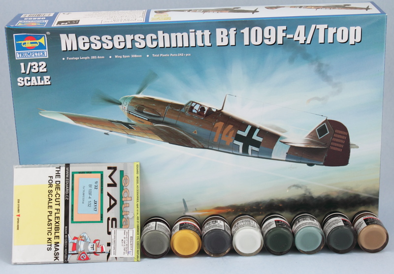
Yes, your eyes are not deceiving you! I'm building an aircraft as part of a bet I lost with a good online friend of mine and selected the Trumpeter 1/32 kit 02293 as my first build in 2014 to pay my debt. Here's the starting materials, will be build OOB with the help of some Eduard masks and a lot of RLM coded paints. Even though I understand the kit isn't 100% accurate regarding it being a true F-4 or a G-2, I'm not going to be doing any modifications to it for the sake of accuratizing it from one model to the other.
-
Bill Plunk
- Posts: 1245
- Joined: Wed Sep 28, 2022 10:18 pm
WIP 12-29-2013
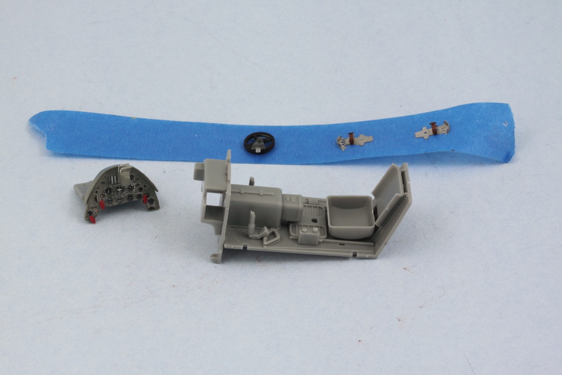
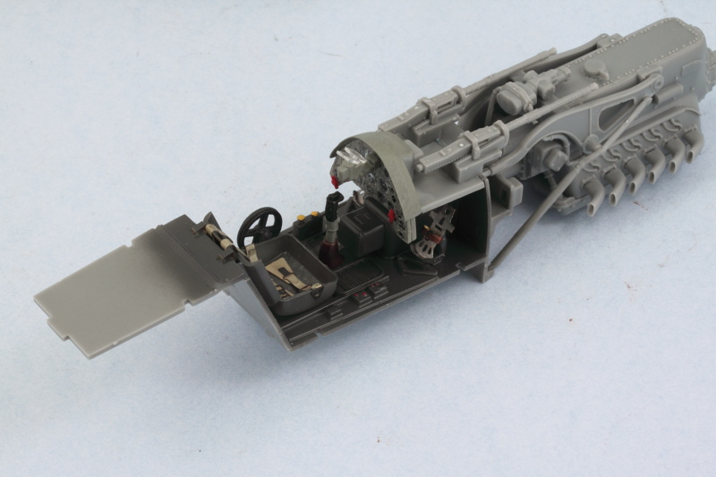
Work began with Step 1 of the instructions dealing with the cockpit areas. I'm going to hold off applying the RLM 66 to the cockpit and fuselage areas until I can airbrush them all at the same time, so I assembled the floor of the cockpit along with firewall and pilot's seat as one module. I kept the rudder pedals (PE), the large hand wheel, and the instrument panel separate from each other for now. I used the kit-supplied IP decal and painted the panel and hood RLM 02, the hand wheel Flat Black and its base/mount RLM 66, and the rudder pedals with MM non-buffing Metalizer Steel and Leather for the straps.
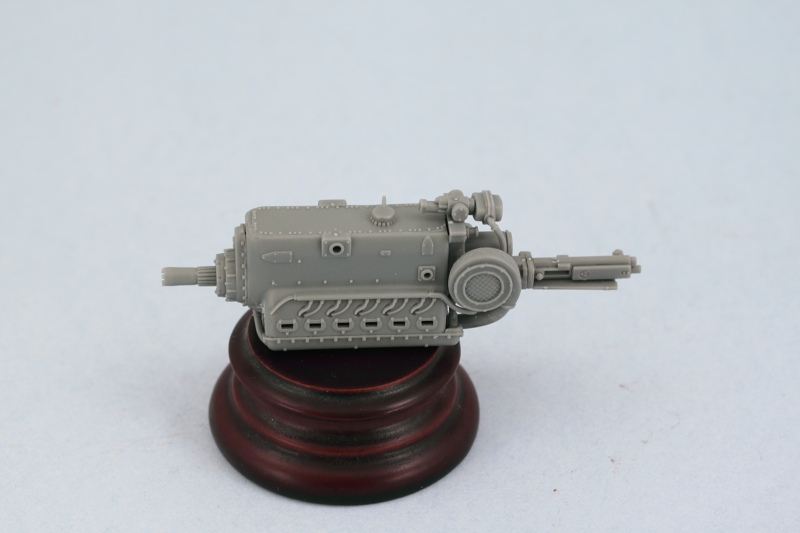
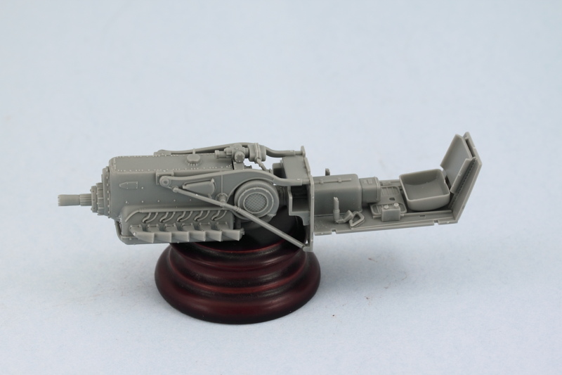
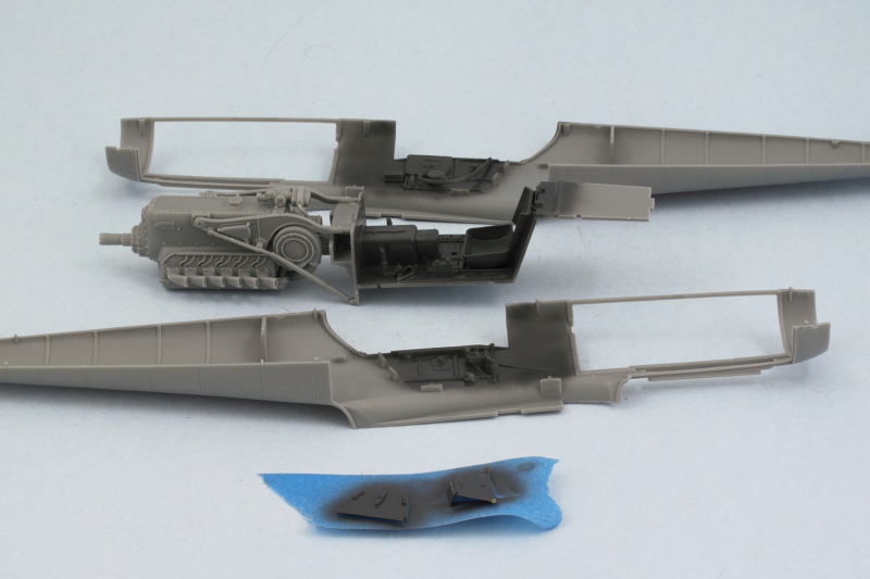
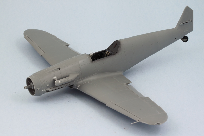
Step 2 deals with the engine and involves a lot of parts that all need to come together to create all the different detail. The fit on some of the parts wasn't that great, requiring some sanding/trimming and a very slight amount of putty work on the engine block in spots to get it all together. End result has a lot of detail though, so that's a plus. The 'fish tail' exhausts were deliberately left off for now until I can decide if I'm going to show one of the engine panels loose or not...and then determine when the best time is to paint and install those exhausts into the engine.
May not seem like a lot but those two steps covered 63 parts out of 242 so roughly 1/4 of the parts in the whole kit. Next up will be continuing work on the pit areas on the fuselage and the remaining details for the engine mounts and guns.
Step 2 deals with the engine and involves a lot of parts that all need to come together to create all the different detail. The fit on some of the parts wasn't that great, requiring some sanding/trimming and a very slight amount of putty work on the engine block in spots to get it all together. End result has a lot of detail though, so that's a plus. The 'fish tail' exhausts were deliberately left off for now until I can decide if I'm going to show one of the engine panels loose or not...and then determine when the best time is to paint and install those exhausts into the engine.
May not seem like a lot but those two steps covered 63 parts out of 242 so roughly 1/4 of the parts in the whole kit.
-
Bill Plunk
- Posts: 1245
- Joined: Wed Sep 28, 2022 10:18 pm
WIP 01-04-2014
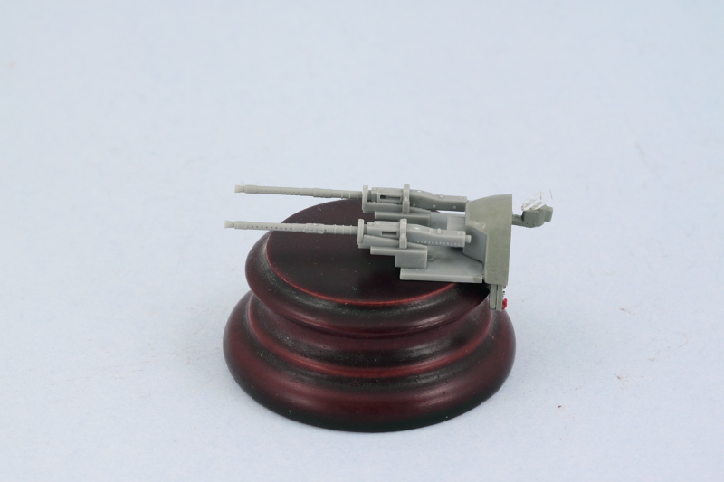
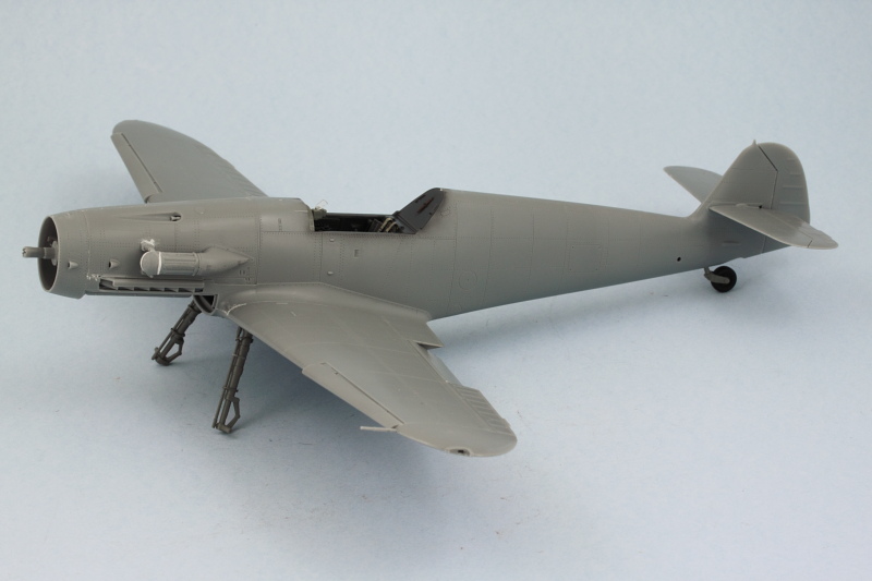
Work continued on the 109 a bit in the cockpit and engine areas. Step 3 adds the twin MGs along with the engine mounts. The MG assembly is a little tricky as the gun barrels fit very loose in their mount points with the gun bases, so getting them aligned properly requires lots of patience and test fits to get it right.
I decided after looking at reference photos and seeing the rather large ejector marks that are present on the engine access panels that I would go ahead and close up the nose and not display it exposed. Trumpeter didn't include all the engine detail (some tanks and other items are missing on the left side in particular) and it will make life simpler to keep things closed up. I added the fishtail exhausts, working one side at a time to ensure they would line up correctly with their openings on the fuselage. Their mount points into the engine block have some play in them so it's essential to get them all lined up just so to avoid issues. I also found that I had to cut away part of the hose assembly on the right hand side to allow the engine brace mount to line up correctly on that side, otherwise everything went together smoothly.
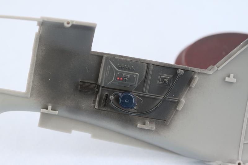
Steps 4 and 5 deal with the landing gear so will cycle back to them later. Steps 6 and 7 add some interior details to the cockpit areas so I tackled them next.
That's as far as things will go this weekend due to the NFL playoff games kicking off, next up will be working on the propeller and other various details as I pick my way through this before starting in on the AB work.
I decided after looking at reference photos and seeing the rather large ejector marks that are present on the engine access panels that I would go ahead and close up the nose and not display it exposed. Trumpeter didn't include all the engine detail (some tanks and other items are missing on the left side in particular) and it will make life simpler to keep things closed up. I added the fishtail exhausts, working one side at a time to ensure they would line up correctly with their openings on the fuselage. Their mount points into the engine block have some play in them so it's essential to get them all lined up just so to avoid issues. I also found that I had to cut away part of the hose assembly on the right hand side to allow the engine brace mount to line up correctly on that side, otherwise everything went together smoothly.
Steps 4 and 5 deal with the landing gear so will cycle back to them later. Steps 6 and 7 add some interior details to the cockpit areas so I tackled them next.
That's as far as things will go this weekend due to the NFL playoff games kicking off, next up will be working on the propeller and other various details as I pick my way through this before starting in on the AB work.
-
Bill Plunk
- Posts: 1245
- Joined: Wed Sep 28, 2022 10:18 pm
WIP 01-12-2014
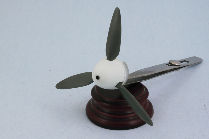
Continuing on with the construction phases, I worked on Step 8 which deals with the propeller and hub assembly. The blades are separate from the two part hub and are nicely molded and the prop shaft has a notch that lines up with the opening inside the spinner cap. This, combined with how the base of the spinner and the tank that attaches to its back all line up mean that the prop can't rotate once everything is installed, so I had to decide how I wanted the prop to align first before committing to glue.

The little side notches on the tank behind the spinner align with tabs on the inside of the fuselage halves to keep everything lined up properly. Currently the prop and spinner are only dry fit together to make it a little easier to paint the prop later on before installing it permanently into the spinner.

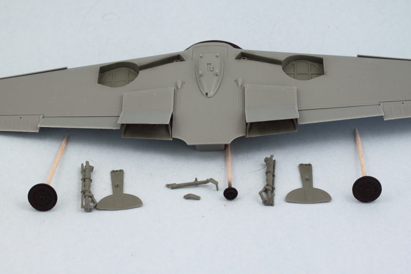
Moving on to Step 9 which deals with the wings, I installed the radiator parts along with their covers/speed flaps. The radiators were painted with MM non-buffing Metalizer and the inside areas of the covers/flaps with MM RLM 02.

Since I wasn't fitting the under-wing gun pods, I skipped the optional parts that support that and added the upper wing halves. The fit here was very good, rather than use rubber bands I opted for smooth jaw clamps placed at strategic points to ensure the glue set evenly with both halves.

While that was setting up, I assembled the two-part elements for the flaps and ailerons and cleaned up the leading-edge slats. In order to position the flaps at the correct dropped angle, I removed the little mount tabs they had on their front edges and carefully glued them into position with liquid glue and used a metal ruler to gauge the correct angle/gap on both sides so they matched up with each other. Ailerons and slats were installed as well to complete the wing assembly.

Step 10 pulls the fuselage together but I'm not quite ready for that, but I did start work on the front nose panel by drilling open the mount holes for the support posts for the air filter and installed the air intake mount as well. The intake is in two halves so careful gluing with liquid glue and a bit of sanding were needed to give it a seamless look.
Last but not least for the day, I assembled the two-part components for the rudder and the horizontal stabilizers as called for in Step 11. The elevators were cleaned up and installed in the level position as well.

Next up will be finishing off some of the remaining construction odds and ends and prepping for painting on the interior before the fuselage gets joined up.
The little side notches on the tank behind the spinner align with tabs on the inside of the fuselage halves to keep everything lined up properly. Currently the prop and spinner are only dry fit together to make it a little easier to paint the prop later on before installing it permanently into the spinner.
Moving on to Step 9 which deals with the wings, I installed the radiator parts along with their covers/speed flaps. The radiators were painted with MM non-buffing Metalizer and the inside areas of the covers/flaps with MM RLM 02.
Since I wasn't fitting the under-wing gun pods, I skipped the optional parts that support that and added the upper wing halves. The fit here was very good, rather than use rubber bands I opted for smooth jaw clamps placed at strategic points to ensure the glue set evenly with both halves.
While that was setting up, I assembled the two-part elements for the flaps and ailerons and cleaned up the leading-edge slats. In order to position the flaps at the correct dropped angle, I removed the little mount tabs they had on their front edges and carefully glued them into position with liquid glue and used a metal ruler to gauge the correct angle/gap on both sides so they matched up with each other. Ailerons and slats were installed as well to complete the wing assembly.
Step 10 pulls the fuselage together but I'm not quite ready for that, but I did start work on the front nose panel by drilling open the mount holes for the support posts for the air filter and installed the air intake mount as well. The intake is in two halves so careful gluing with liquid glue and a bit of sanding were needed to give it a seamless look.
Last but not least for the day, I assembled the two-part components for the rudder and the horizontal stabilizers as called for in Step 11. The elevators were cleaned up and installed in the level position as well.
Next up will be finishing off some of the remaining construction odds and ends and prepping for painting on the interior before the fuselage gets joined up.
-
Bill Plunk
- Posts: 1245
- Joined: Wed Sep 28, 2022 10:18 pm
WIP 01-17-2014
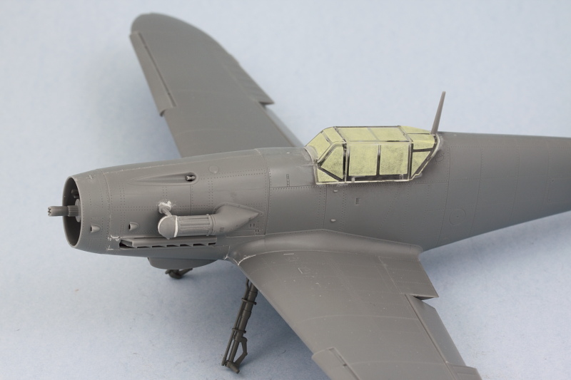
Sometimes it amazes me how the smallest of things can often times cause the biggest headaches on a build. On this particular build, that turned out to be the case with the "Tropen" filter fitted to the large air intake on the cowling. For whatever reason Trumpeter designed the front 'clam-shell' doors on the filter to be installed only in the 'open' configuration...something that makes no sense really when you think about it especially as all the reference photos I was able to find of Trops on the ground showing it closed to, of course, allow the filtration to actually work. To get a 'closed' look on the filter front required some extensive re-working of the kit parts. As molded, they don't meet up correctly if 'closed', so I had to use a good bit of putty and sanding to reshape the front parts into something closer to what it should actually look like and fair it back in with the rest of the filter.
The issues didn't stop there however...the mount arms/pins that support the filter also had to be modified. With the doors now covering the holes that the pins would go into, the pins were trimmed off and I installed the bottom support first to get it properly lined up with the normal intake. When it came time to install the top, it became abundantly clear that the holes that the instructions called to be drilled out earlier were too high for the top bar to meet up with the filter as it should. That meant filling those holes, trimming off the pins, and moving the mount low enough (and also shortening its support arm to the right length)to match up properly with the filter.

So something that started out being just a simple installation turned into a major modification that took a couple of hours to resolve!
The issues didn't stop there however...the mount arms/pins that support the filter also had to be modified. With the doors now covering the holes that the pins would go into, the pins were trimmed off and I installed the bottom support first to get it properly lined up with the normal intake. When it came time to install the top, it became abundantly clear that the holes that the instructions called to be drilled out earlier were too high for the top bar to meet up with the filter as it should. That meant filling those holes, trimming off the pins, and moving the mount low enough (and also shortening its support arm to the right length)to match up properly with the filter.
So something that started out being just a simple installation turned into a major modification that took a couple of hours to resolve!
-
Bill Plunk
- Posts: 1245
- Joined: Wed Sep 28, 2022 10:18 pm
WIP 01-19-2014
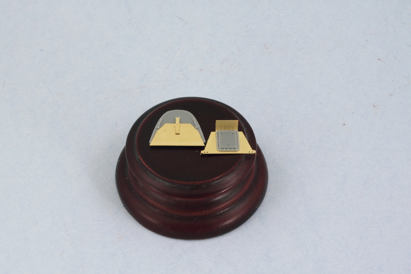
The work on getting the major components ready for painting continued with the assembly of the belly tank and mount as called for in Step 13. The tank itself is in two halves and getting it to mate up properly at the rear required some extra coaxing and pressure supplied with a smooth clamp to allow the glue to grab and hold properly. Once the tank had set, I sanded down the join seam and added the PE center band as well as the mounting hardware to the tank's top. The belly mount itself was attached to the wing underside instead of installing it to the tank to allow for a better join with the wing as well as make it easier to paint the tank itself. Part G5 from Step 14 was added at this point as well to provide the front half of the mount point for the tank mount.

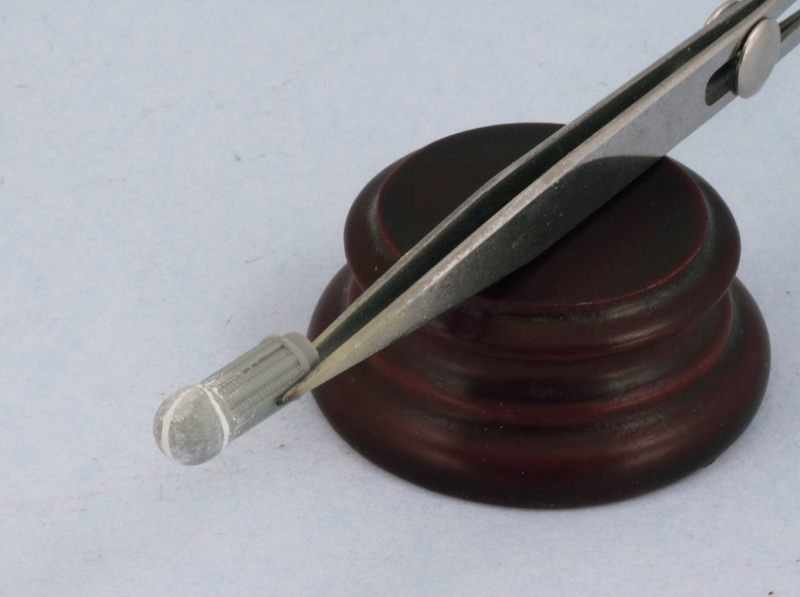
Continuing with the underside elements, I went back to Steps 4 and 5 to deal with the main landing gear. The struts were assembled and ejector marks removed or filled where appropriate on the struts and covers. The PE straps for the brake lines were annealed and then attached using liquid glue to help position them properly on the struts. The two part wheel hubs were assembled and the vinyl tires cleaned up by gently sanding away their mold seam and trimming away flash on the insides of their rims with the point of sharp #11 blade.

Jumping back to Step 14, the underside engine cowl and intake were assembled with the kit-provided PE screen added. The cover will be painted separately prior to its installation.

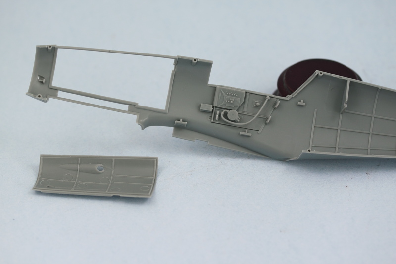
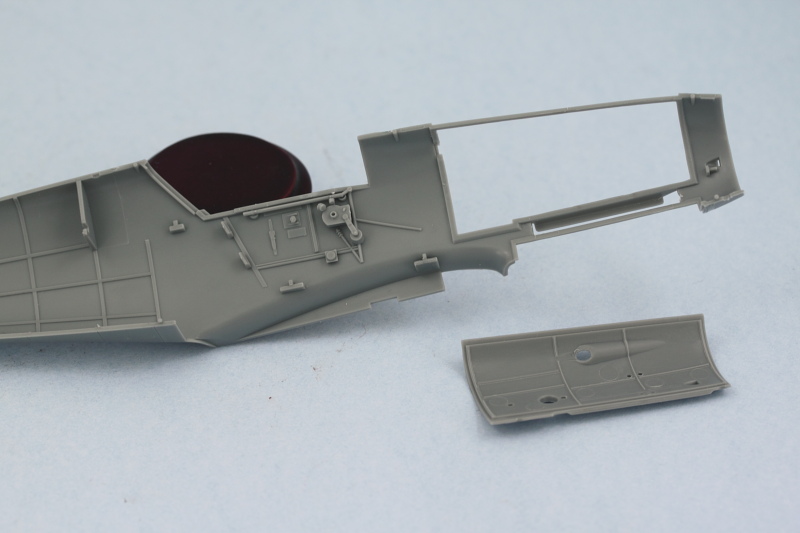
Rounding out the session's activity, I added the rear extension plate to the cockpit that's installed separately in Step 10 as part of the fuselage joining process. I used the fuselage halves to dry-fit the part, L5, to line it up properly with the pilot's seat back and then carefully glued it in place while still inside the fuselage halves to give it some support so it would set at the correct level position. Once set, I added the PE mount for the top pilot's harness straps to get it ready for airbrushing.

It's been a bit of a surprise just how much time has been consumed by these steps to get stuff ready for painting but almost there! Just need to clean up the tail wheel mount and get the cockpit clear pieces masked and ready and some paint can start to fly on the various components.
Continuing with the underside elements, I went back to Steps 4 and 5 to deal with the main landing gear. The struts were assembled and ejector marks removed or filled where appropriate on the struts and covers. The PE straps for the brake lines were annealed and then attached using liquid glue to help position them properly on the struts. The two part wheel hubs were assembled and the vinyl tires cleaned up by gently sanding away their mold seam and trimming away flash on the insides of their rims with the point of sharp #11 blade.
Jumping back to Step 14, the underside engine cowl and intake were assembled with the kit-provided PE screen added. The cover will be painted separately prior to its installation.
Rounding out the session's activity, I added the rear extension plate to the cockpit that's installed separately in Step 10 as part of the fuselage joining process. I used the fuselage halves to dry-fit the part, L5, to line it up properly with the pilot's seat back and then carefully glued it in place while still inside the fuselage halves to give it some support so it would set at the correct level position. Once set, I added the PE mount for the top pilot's harness straps to get it ready for airbrushing.
It's been a bit of a surprise just how much time has been consumed by these steps to get stuff ready for painting but almost there! Just need to clean up the tail wheel mount and get the cockpit clear pieces masked and ready and some paint can start to fly on the various components.
-
Bill Plunk
- Posts: 1245
- Joined: Wed Sep 28, 2022 10:18 pm
WIP 01-20-2014
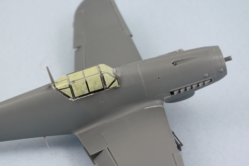
Due to the Martin Luther King, Jr. holiday, here's a bit of a bonus update! The last little details needing to be taken care of involved the door to the pilot's storage compartment and the armored headrest. The compartment door is taken care of in Step 11 and installs after the fuselage is joined, so getting ready for paint beforehand saves some time later on. The headrest is dealt with in Step 12 along with the rest of the canopy details. Although not pictured in the shot below, I began the prep work on the canopy parts as well by dipping them in Future and setting them off to the side to dry/cure before they are masked and painted later on.
Then it was time to have some fun with the airbrush. Flat white and RLM 70 did the trick for the propeller blades and spinner. After the paint had dried, they were joined together and the cannon opening detailed with MM non-buffing Metalizer Gunmetal and a light dry-brushing of Steel.
Wheel wells, landing gear struts, and gear doors got a dose of RLM 02 while the wheel hubs were done in Flat Black.
Rounding things out, the cockpit elements received their RLM 66 finish in anticipation of further detail work to come.
Paint has finally flown on this bird!
-
Bill Plunk
- Posts: 1245
- Joined: Wed Sep 28, 2022 10:18 pm
WIP 01-25-2014
Made a lot of progress over the last few days working on the cockpit details a little bit at a time and then doing a lot of major assembly work today. First up, the pit details. I used the kit-supplied PE for the pilot's harness and detailed all the various buttons and knobs to provide some color. The rudder pedals that were done previously also got installed and then the instrument panel was put into its permanent position. I used the fuselage halves held together with rubber bands to ensure the IP and gun mounts were at the right angle as the attachment points to the engine firewall bulkhead aren't that deep or strong.


Then the moment of truth arrived, it was time to join the fuselage halves together. I added the tail wheel to the right side first and let that glue set up a little bit before joining the halves. Strategic use of rubber bands and smooth jaw clamps helped get a good join all around. I used a combination of liquid glue and regular glue as well on the different areas.
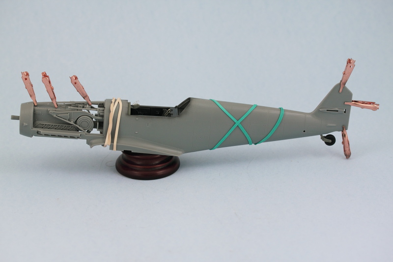
After about an hour for the glue to set, the clamps and bands were removed, the join was lightly sanded where needed, and then a very light pass of liquid glue applied over the sanded areas to remove the dust and fine scratches prior to painting. Then the real fun began with the engine cowls. The fit on these is generally good but both sides required careful use of finger pressure and liquid glue to get everything to line up properly and take the right shape. For the right hand cowl, I had to remove the middle portion of the lower engine mount, part L3 installed in Step 3, as it was keeping the cowl from fitting properly. Not sure if I introduced that issue or if it's a dimension flaw in the kit, but a quick snip with the sprue cutters removed the offending section easily enough.
Next up was the wing installation. I knew from previous dry-fits that this was going to be more of a challenge to get a good join at the wing roots so was prepared for that. I had to use finger pressure and lift up on the wing undersides to get the top sides to mate up properly and close the gap, so for a good 15 minutes I sat at my bench and waited as there was no other way using either clamps or bands to get the correct tension on them to close it up. After the glue had caught enough to hold the right angles, I used small amounts of putty at the front of the joins on both sides to fill a small gap that couldn't be closed up otherwise. The gap on the left wing extended about 5mm in from the edge while the right wing was about 3x longer, just a function of the way the different sides came together.
Last but not least, I dry fit the main landing gear struts so I could check to ensure everything was sitting level and installed the horizontal stabilizers at the rear. The rudder is dry-fit only just to make sure everything was playing nice back there.
Tomorrow will see major paint work start in on the fuselage if everything goes according to plan.
Then the moment of truth arrived, it was time to join the fuselage halves together. I added the tail wheel to the right side first and let that glue set up a little bit before joining the halves. Strategic use of rubber bands and smooth jaw clamps helped get a good join all around. I used a combination of liquid glue and regular glue as well on the different areas.
After about an hour for the glue to set, the clamps and bands were removed, the join was lightly sanded where needed, and then a very light pass of liquid glue applied over the sanded areas to remove the dust and fine scratches prior to painting. Then the real fun began with the engine cowls. The fit on these is generally good but both sides required careful use of finger pressure and liquid glue to get everything to line up properly and take the right shape. For the right hand cowl, I had to remove the middle portion of the lower engine mount, part L3 installed in Step 3, as it was keeping the cowl from fitting properly. Not sure if I introduced that issue or if it's a dimension flaw in the kit, but a quick snip with the sprue cutters removed the offending section easily enough.
Next up was the wing installation. I knew from previous dry-fits that this was going to be more of a challenge to get a good join at the wing roots so was prepared for that. I had to use finger pressure and lift up on the wing undersides to get the top sides to mate up properly and close the gap, so for a good 15 minutes I sat at my bench and waited as there was no other way using either clamps or bands to get the correct tension on them to close it up. After the glue had caught enough to hold the right angles, I used small amounts of putty at the front of the joins on both sides to fill a small gap that couldn't be closed up otherwise. The gap on the left wing extended about 5mm in from the edge while the right wing was about 3x longer, just a function of the way the different sides came together.
Last but not least, I dry fit the main landing gear struts so I could check to ensure everything was sitting level and installed the horizontal stabilizers at the rear. The rudder is dry-fit only just to make sure everything was playing nice back there.
Tomorrow will see major paint work start in on the fuselage if everything goes according to plan.
-
Bill Plunk
- Posts: 1245
- Joined: Wed Sep 28, 2022 10:18 pm
WIP 01-26-2014
Everything went according to plan today except I didn't get to paint. That's because the remaining 'little' items ended up taking up the full session today to square away.
The first area that consumed a lot of time was the canopy. The three clear parts had been previously dipped in Future but left on little sprue 'handles' to make it easier to work with them. Those handles were removed today and the small details added where needed in the different elements of the canopy.
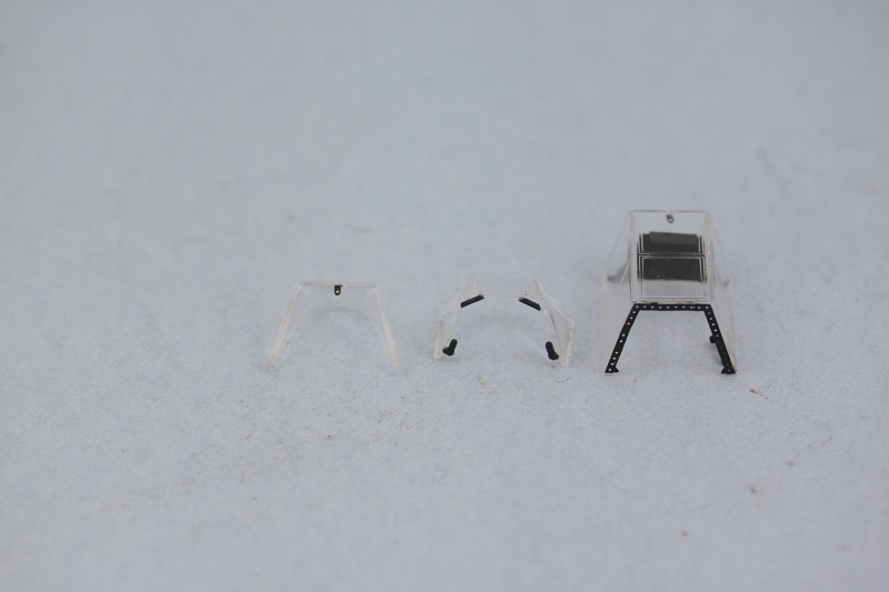
In hindsight, I probably should've waited to do this until after I had applied the Eduard masks as a couple parts broke loose while handling them during that process, but they were easily reattached. I had been toying with the idea of posing the canopy open but decided against that due to the complexities it would present in the paint and finish stages. This led to some small issues popping up in terms of the overall fit of the three pieces together and their alignment with the fuselage. The fit is ok but not perfect and while the three pieces fit tightly together, the fit of the front piece and the rear piece to the fuselage required some help after they were installed in the form of sanding and putty in different places.
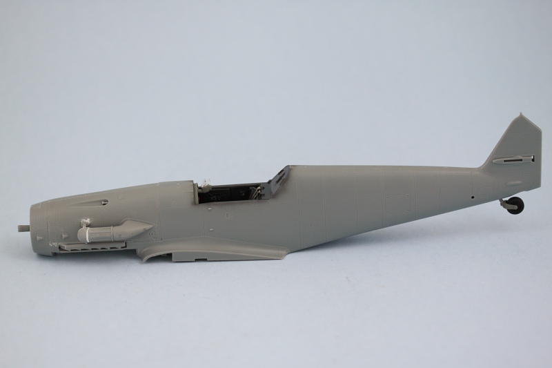
The other remaining detail to take care of was the bottom engine cowl panel. I had planned to paint it separately but after doing some test fits I realized it was going to need the same finger pressure/squeezing/coaxing attention with liquid glue that the top panels needed. Trying to do that with painted areas is a recipe for disaster so I went ahead and installed it in place, using some small amounts of putty on the underside to fill small gaps at the wing roots where it matches up with the wing sections.
When it comes time to install the prop and spinner, I'm going to have to apply some tension to get the engine and drive-shaft to move into the correct alignment so that the spinner sits correctly in relation to the fuselage...but that will have to be done after painting as I need to be able to get at the areas around the exhausts for their detailing and also the masking demarcation for the blue/tan separation. I may just clip off the drive-shaft and attach the spinner directly, have to see which one is the easiest to do under the circumstances.
Last but not least, I installed the main antenna mast, the smaller lower fuselage antenna, and the aileron counter-weights to get this ready to paint.
The first area that consumed a lot of time was the canopy. The three clear parts had been previously dipped in Future but left on little sprue 'handles' to make it easier to work with them. Those handles were removed today and the small details added where needed in the different elements of the canopy.
In hindsight, I probably should've waited to do this until after I had applied the Eduard masks as a couple parts broke loose while handling them during that process, but they were easily reattached. I had been toying with the idea of posing the canopy open but decided against that due to the complexities it would present in the paint and finish stages. This led to some small issues popping up in terms of the overall fit of the three pieces together and their alignment with the fuselage. The fit is ok but not perfect and while the three pieces fit tightly together, the fit of the front piece and the rear piece to the fuselage required some help after they were installed in the form of sanding and putty in different places.
The other remaining detail to take care of was the bottom engine cowl panel. I had planned to paint it separately but after doing some test fits I realized it was going to need the same finger pressure/squeezing/coaxing attention with liquid glue that the top panels needed. Trying to do that with painted areas is a recipe for disaster so I went ahead and installed it in place, using some small amounts of putty on the underside to fill small gaps at the wing roots where it matches up with the wing sections.
When it comes time to install the prop and spinner, I'm going to have to apply some tension to get the engine and drive-shaft to move into the correct alignment so that the spinner sits correctly in relation to the fuselage...but that will have to be done after painting as I need to be able to get at the areas around the exhausts for their detailing and also the masking demarcation for the blue/tan separation. I may just clip off the drive-shaft and attach the spinner directly, have to see which one is the easiest to do under the circumstances.
Last but not least, I installed the main antenna mast, the smaller lower fuselage antenna, and the aileron counter-weights to get this ready to paint.
-
Bill Plunk
- Posts: 1245
- Joined: Wed Sep 28, 2022 10:18 pm
WIP 02-02-2014
The much anticipated painting sessions arrived this weekend, first order of business was the application of a pre-shade pass with Flat Black.
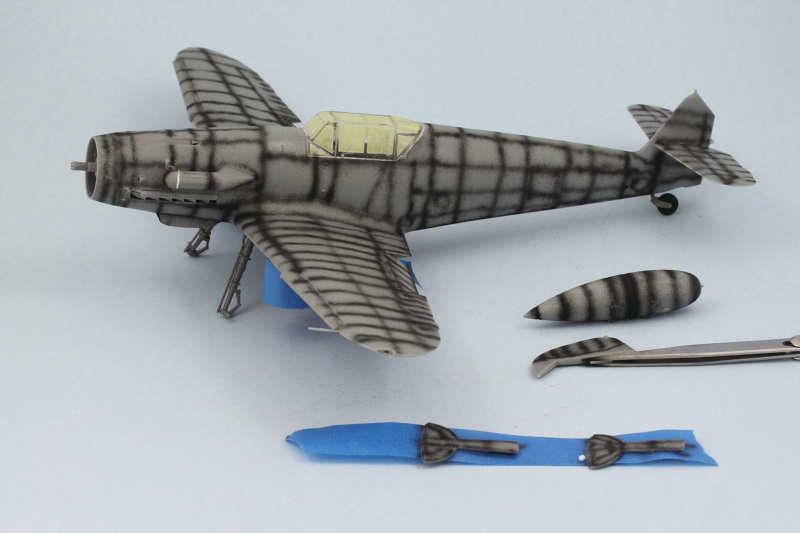
Canopy was airbrushed with the RLM 66 so it would show as the inner color on the frame and the rudder was airbrushed with Insignia Red. Since the kill markings decals have to go here, I figure it will be easier to work with it off the model and then attach it later.

Next came the application of the RLM 79 Tropen top-side color, airbrushed in light passes to build it up and still retain the pre-shade effects where desired.
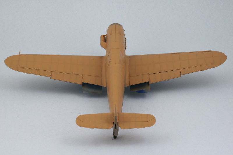

After that had been allowed to set up overnight, I masked off the demarcation line and then airbrushed the RLM 78 lower/underside color. Same approach, light passes to build it up over the pre-shade.
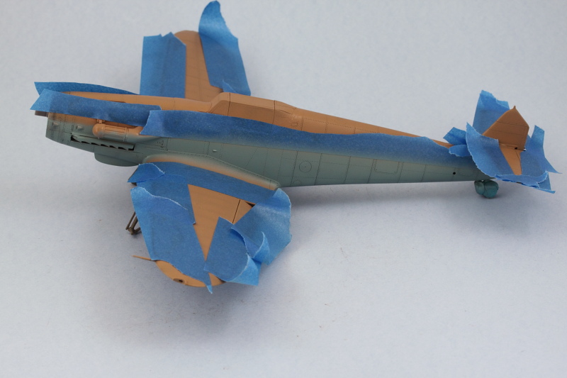
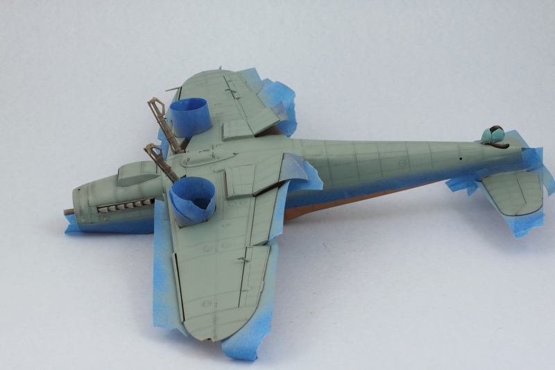
That was allowed to dry for a couple of hours and then more masking and painting sessions to get the white wing tips and fuselage band on and then finally the RLM 04 lower engine access panel.
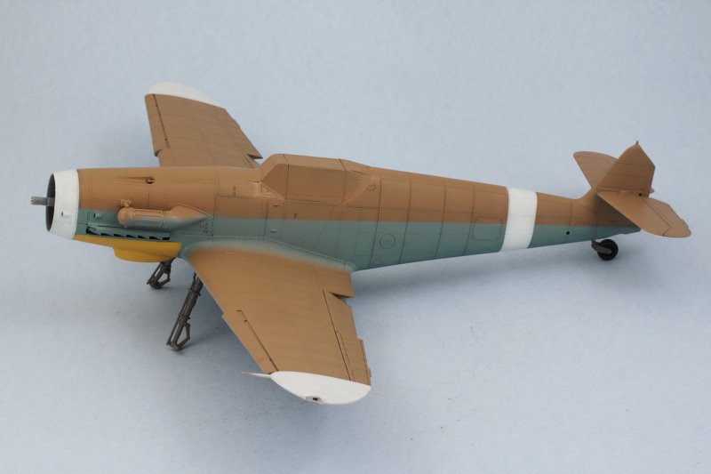
After checking reference photos for Marseilles' 109, it looks like the front cap on the air filter is also white, so that's why it looks a little unfinished at the moment. It's going to be painted by hand along with the other remaining details in the next round.
Now it's time to go watch the Super Bowl!
Canopy was airbrushed with the RLM 66 so it would show as the inner color on the frame and the rudder was airbrushed with Insignia Red. Since the kill markings decals have to go here, I figure it will be easier to work with it off the model and then attach it later.
Next came the application of the RLM 79 Tropen top-side color, airbrushed in light passes to build it up and still retain the pre-shade effects where desired.
After that had been allowed to set up overnight, I masked off the demarcation line and then airbrushed the RLM 78 lower/underside color. Same approach, light passes to build it up over the pre-shade.
That was allowed to dry for a couple of hours and then more masking and painting sessions to get the white wing tips and fuselage band on and then finally the RLM 04 lower engine access panel.
After checking reference photos for Marseilles' 109, it looks like the front cap on the air filter is also white, so that's why it looks a little unfinished at the moment. It's going to be painted by hand along with the other remaining details in the next round.
Now it's time to go watch the Super Bowl!