Trumpeter 1/350 HMS Dreadnought 1907 (2014)
-
Bill Plunk
- Posts: 1245
- Joined: Wed Sep 28, 2022 10:18 pm
Trumpeter 1/350 HMS Dreadnought 1907 (2014)
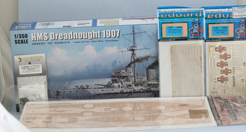
Build log for Trumpter's 1/350 kit #05328 HMS Dreadnought 1907.
-
Bill Plunk
- Posts: 1245
- Joined: Wed Sep 28, 2022 10:18 pm
WIP 08-04-2014
Dreadnought project took its first steps today in terms of getting the hull together. The first step in the Trumpeter instructions assembles the two-part full hull along with 7 internal braces to stiffen the hull and also provide some support for the main deck. I had heard about other builders having issues with a gap in the hull join particularly in the middle, so I did a test fit first to see how things would play together.
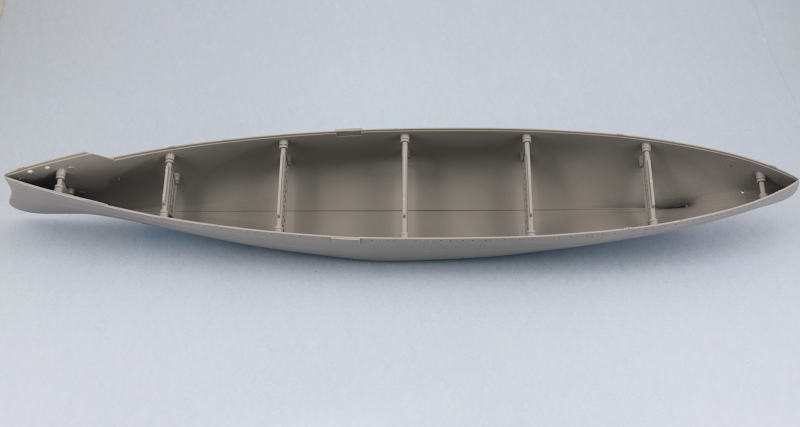
What I noticed was that the hull fit together very well at the bow and stern and only in the middle was there a slight gap. I also noticed that the braces had a very tight friction fit except for the smaller bow/stern braces into their mounting holes. I used some strips of masking tape along the bottom of the hull and then positioned each of the braces, squeezing in from the sides so that they would close up evenly. Once I did that, the slight gap in the bottom virtually disappeared and what remained could be closed up with some strategic pressure and rubber bands. I applied some liquid glue at the bow and stern first and used finger pressure to close those up until they set so I had a solid place to start from.
Then to avoid any problems with the hull potentially warping at the top while I worked on the bottom, I used the main deck insert to help it hold its position and taped it down, then added two rubber bands to help wit the small gap on the bottom.
Starting at the bow and working my way back, I applied liquid glue in small sections and gently squeezed the hull together in combination with the rubber bands until the glue 'grabbed', then moved further down the seam repeating the process.
After the glue had set, the rubber bands came off and some light sanding of the seam using sanding sticks was all that was needed. I did need to apply just a small amount of putty around the propeller shaft area of the seam on the stern. This was due to a slight gap created when I removed the sprue connection point there though and not something inherent in the kit.
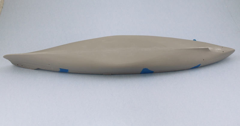
Last but not least, I knocked together the kit-supplied stand so I could have something to rest the hull on. I'm not too thrilled with it as a permanent base but it will serve for now.
The main deck insert sits flush with the hull top edge so I can already tell that when I add the wood decking it will increase the deck height ever so slightly. I think that's actually going to be to my advantage though in terms of helping provide just a smidge of added contact surface for the railings but have to see about that when the time comes.
What I noticed was that the hull fit together very well at the bow and stern and only in the middle was there a slight gap. I also noticed that the braces had a very tight friction fit except for the smaller bow/stern braces into their mounting holes. I used some strips of masking tape along the bottom of the hull and then positioned each of the braces, squeezing in from the sides so that they would close up evenly. Once I did that, the slight gap in the bottom virtually disappeared and what remained could be closed up with some strategic pressure and rubber bands. I applied some liquid glue at the bow and stern first and used finger pressure to close those up until they set so I had a solid place to start from.
Then to avoid any problems with the hull potentially warping at the top while I worked on the bottom, I used the main deck insert to help it hold its position and taped it down, then added two rubber bands to help wit the small gap on the bottom.
Starting at the bow and working my way back, I applied liquid glue in small sections and gently squeezed the hull together in combination with the rubber bands until the glue 'grabbed', then moved further down the seam repeating the process.
After the glue had set, the rubber bands came off and some light sanding of the seam using sanding sticks was all that was needed. I did need to apply just a small amount of putty around the propeller shaft area of the seam on the stern. This was due to a slight gap created when I removed the sprue connection point there though and not something inherent in the kit.
Last but not least, I knocked together the kit-supplied stand so I could have something to rest the hull on. I'm not too thrilled with it as a permanent base but it will serve for now.
The main deck insert sits flush with the hull top edge so I can already tell that when I add the wood decking it will increase the deck height ever so slightly. I think that's actually going to be to my advantage though in terms of helping provide just a smidge of added contact surface for the railings but have to see about that when the time comes.
-
Bill Plunk
- Posts: 1245
- Joined: Wed Sep 28, 2022 10:18 pm
WIP 08-05-2014
Day 2 of the Dreadnought project saw the main deck get installed permanently in place. Overall the fit of the deck is quite good with just a little bit of pressure needed at the top sides in a couple of spots. I used liquid glue and some strategically placed rubber bands to hold it all together while the glue set.

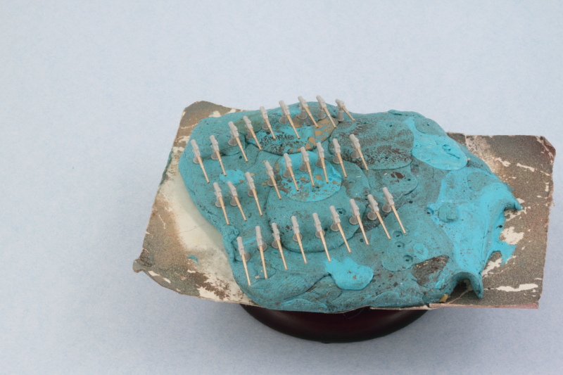
While that was going on I turned my attention to the main guns and turrets. The kit-provided barrels have the blast bags molded on and depends on those as the contact points for the barrels to be installed. The blast bags weren't fitted in 1907 and my Master replacement barrels are the correct shape and length but have the standard pins on their bases...but there's nothing to actually attach them to. Fortunately the kit provides 6 turrets on the sprues so I decided on a little test first.
I took some Aves epoxy-sculpt and mixed together a small amount to provide the means to mount the barrels. The trick here is that the replacement barrels need to have some of their bases inside the turret to be the right length but getting that right with both barrels can be tricky. Fortunately the Kagero book includes scale drawings with a top down plan view included, so I used that as my guide on how far the barrels should extend. The Aves is a two-part epoxy putty that will dry hard as a rock once it cures but has a good bit of work time, just the right amount of flexibility needed in this circumstance.

The base of the turret was added once I was sure I had the length and placement correct, but not glued in place. Adding the base caused the barrels to change their position and elevation just a bit due to the nature of the turret design and the general alignment.

Just to be sure I had things lined up correctly, I placed the turret in the A mount on the super deck and used a wooden toothpick balanced on one of the sky lights to ensure the gun barrels would hold the proper elevation while the Aves set up.

I'll leave that overnight to see if the experiment was a success...if it is, then I'll repeat it with the other 4 turrets needed and go from there. Fingers crossed!
While that was going on I turned my attention to the main guns and turrets. The kit-provided barrels have the blast bags molded on and depends on those as the contact points for the barrels to be installed. The blast bags weren't fitted in 1907 and my Master replacement barrels are the correct shape and length but have the standard pins on their bases...but there's nothing to actually attach them to. Fortunately the kit provides 6 turrets on the sprues so I decided on a little test first.
I took some Aves epoxy-sculpt and mixed together a small amount to provide the means to mount the barrels. The trick here is that the replacement barrels need to have some of their bases inside the turret to be the right length but getting that right with both barrels can be tricky. Fortunately the Kagero book includes scale drawings with a top down plan view included, so I used that as my guide on how far the barrels should extend. The Aves is a two-part epoxy putty that will dry hard as a rock once it cures but has a good bit of work time, just the right amount of flexibility needed in this circumstance.
The base of the turret was added once I was sure I had the length and placement correct, but not glued in place. Adding the base caused the barrels to change their position and elevation just a bit due to the nature of the turret design and the general alignment.
Just to be sure I had things lined up correctly, I placed the turret in the A mount on the super deck and used a wooden toothpick balanced on one of the sky lights to ensure the gun barrels would hold the proper elevation while the Aves set up.
I'll leave that overnight to see if the experiment was a success...if it is, then I'll repeat it with the other 4 turrets needed and go from there. Fingers crossed!
-
Bill Plunk
- Posts: 1245
- Joined: Wed Sep 28, 2022 10:18 pm
WIP 08-06-2014
So after letting the first turret set up as a test bed (it set hard as a rock, so that part worked wonders), I realized that one of the limitations of this approach was ensuring the gun separation and alignment between the two barrels stayed the same. I thought about constructing a jig or support for the barrels outside the turret to help with that and then opted instead to use a piece of sprue inside the turret. So back to the Kagero scale drawings I went, used some small pieces of blue tack to hold the barrels in place over the drawings, and then marked a section of sprue at the correct width. Drilled out two holes and then test fit the barrels and the sprue piece inside the turret to make sure it would all fit and line up correctly with the barrels at the right length.

Process was repeated 3 times for the remaining four turrets to get their little supports and then CA gel used to permanently secure the barrels to the sprue chunk.

When I test fit the barrels with the turret bottoms and in the mounts on the hull, there was still too much play in the barrels, so I solved that issue by adapting my first test approach and using some more Aves epoxy sculpt to secure the bases.

This combo did the trick nicely while still allowing for some minor height adjustments with the different turrets. The turrets were placed and no toothpicks were needed this time around.


Still a lot more to do in terms of detailing the turrets but the guns themselves are now securely installed. One of those details is the 12pdr guns, so I started work on those. Clipped off the styrene barrel at the appropriate point and drilled a mount hole with a #78 micro drill and used CA gel to secure the Master brass barrel to the breech. There's 27 of these so this will take a little time to get them all done.

Process was repeated 3 times for the remaining four turrets to get their little supports and then CA gel used to permanently secure the barrels to the sprue chunk.
When I test fit the barrels with the turret bottoms and in the mounts on the hull, there was still too much play in the barrels, so I solved that issue by adapting my first test approach and using some more Aves epoxy sculpt to secure the bases.
This combo did the trick nicely while still allowing for some minor height adjustments with the different turrets. The turrets were placed and no toothpicks were needed this time around.
Still a lot more to do in terms of detailing the turrets but the guns themselves are now securely installed. One of those details is the 12pdr guns, so I started work on those. Clipped off the styrene barrel at the appropriate point and drilled a mount hole with a #78 micro drill and used CA gel to secure the Master brass barrel to the breech. There's 27 of these so this will take a little time to get them all done.
-
Bill Plunk
- Posts: 1245
- Joined: Wed Sep 28, 2022 10:18 pm
WIP 08-07-2014
Managed to get all 27 of the 12pdrs built and ready for use. The Trumpeter instructions incorrectly tell you to install 29 of them (and provide 32 in total on the sprues), but the two port-side bow guns that are called for in Step 12 weren't installed on the actual ship, so that's something for the unwary to watch out for.
The rest of the day was spent prepping the main deck and super deck for the Wood Hunter set. I wanted to see how the set would fit and also get a handle on what could be installed prior to painting and what would have to wait until after the decks were added. The main deck is a snug fit in all respects and has the wood go right up to the outline for the super deck, so I'll have to trim that back slightly so the super deck can sit at the proper height and alignment.
The rear deck area had a snug fit as well and the Eduard upgrade parts for some of the hatches and other elements are slightly wider than the kit's molded on versions, so that would've been a complication if I'd installed them first before the deck, so those will have to come after where appropriate.
The super deck's insert is all one piece, so that means it's going to have to be installed first and then the enclosed faces of the superstructure portion added after.
All in all I'm impressed with the deck so far, very little in the way of modifications appear to be needed to make it work, at least for the main parts.
-
Bill Plunk
- Posts: 1245
- Joined: Wed Sep 28, 2022 10:18 pm
WIP 08-08-2014
Not a huge update today but still managed some progress. After studying the instructions and doing some test fits with the front of the superstructure parts (C4, C5, and B42 in Step 4) and the bases of the funnels (A16 and A19) and the boat deck (C30), I decided to split the wood deck insert into two pieces for better handling and fit arrangement. The wood deck needed some trimming around the base of the rear funnel as well as the small blockhouse structure at the front of the interior compartment, but otherwise everything else fit like it should. The funnel and boat deck bases are only dry-fit but the front of the superstructure was permanently installed in place to make it easier to paint this area later on.

One of the things I noticed while working on the bow area was that you could see straight through the hawseholes from one side to the other. To fix that, I cut a strip of white styrene and glued it in place to blank off one set from the other.

The moment of truth had arrived, time to secure the super deck in place. Overall the fit was good except at the angled area where it joined the bow. Both sides needed some putty and sanding work with the starboard side needing more due to a larger gap.


I deliberately left off the top part of the aft superstructure, part A20, as it makes it harder to install the wood deck as well as the pair of 12pdr guns that go in that spot, so it will end up getting painted separately and installed later when the time comes. Not sure how much further I'll go before painting the first round of stuff...I'm thinking of doing it in two phases with the hull going first and then dealing with the turrets and superstructure components second to break things up a bit.
One of the things I noticed while working on the bow area was that you could see straight through the hawseholes from one side to the other. To fix that, I cut a strip of white styrene and glued it in place to blank off one set from the other.
The moment of truth had arrived, time to secure the super deck in place. Overall the fit was good except at the angled area where it joined the bow. Both sides needed some putty and sanding work with the starboard side needing more due to a larger gap.
I deliberately left off the top part of the aft superstructure, part A20, as it makes it harder to install the wood deck as well as the pair of 12pdr guns that go in that spot, so it will end up getting painted separately and installed later when the time comes. Not sure how much further I'll go before painting the first round of stuff...I'm thinking of doing it in two phases with the hull going first and then dealing with the turrets and superstructure components second to break things up a bit.
-
Bill Plunk
- Posts: 1245
- Joined: Wed Sep 28, 2022 10:18 pm
WIP 08-10-2014
Continuing on with the efforts aimed at the hull details and getting it ready for the first round of painting, I decided to add the screen covers to the front part of the anchor chain guide holes, a missing detail that isn't covered in either the Eduard PE sets or the kit. I tried several different ways of scratch-building this item including using sheet styrene and drilling out holes by hand and using some nylon mesh screen material but neither of these produced the desired result. After scrounging around in my spares bin, I found some old photo-etched steel Pzkpfw III intake screens that had what I wanted.
The challenge was to cut them to the right shape...so I created a pattern by taking a pencil and doing a rubbing with a piece of white paper over the hole's opening on the super deck to get the outline. This was cut out and then photocopied onto another sheet and only the front half trimmed out. Using some sharp sturdy scissors, I cut the mesh into the desired shape and then fine tuned it with Tamiya sprue cutters where needed until I had three suitably sized screens. The screens were glued in place with liquid glue and gently pressed down with a wooden toothpick into the desired position.


The next little detail that I needed to add were the 16 'ribs' that were welded over the waterline belt armor plate join seams on each side of the hull but which Trumpeter neglected. These can be clearly seen on the plans and in reference photos as having some thickness out from the hull vs. being just flat strips, so I settled on using some 0.6mm diameter styrene rod to do the job. They had the right width but needed to be flattened, so I secured the rod with a length of masking tape and used a sanding stick to flatten one side, then turned the rod over and flattened the other side.

The Kagero 3D scale plans were invaluable in determining their height and placement around the hull and it was through this process that I realized that Trumpeter 'mirrored' some of the hull details in terms of number/placement of portholes and hatches so in those cases my 'fall back' landmarks of choice were the torpedo net booms.

Speaking of the booms, those came next. In some spots where the booms needed to pass over the ribs, some additional sanding/flattening was needed but otherwise everything mostly played nice with each other. The kit parts only give you the option of having the booms in the stowed position and of course there's no torpedo net provided for but I'm not worried about that for my purposes.

Next were the keels. Both of mine had some warping to different degrees and in different spots on their respective parts, so some careful work with liquid glue and positioning in terms of starting at the front and working my way along in small sections was necessary to get them both in place and lined up properly.

Rounding out this stage of activity, the propeller shafts, support struts, and rudders were installed.

Tomorrow will likely see the first round of painting depending!
The challenge was to cut them to the right shape...so I created a pattern by taking a pencil and doing a rubbing with a piece of white paper over the hole's opening on the super deck to get the outline. This was cut out and then photocopied onto another sheet and only the front half trimmed out. Using some sharp sturdy scissors, I cut the mesh into the desired shape and then fine tuned it with Tamiya sprue cutters where needed until I had three suitably sized screens. The screens were glued in place with liquid glue and gently pressed down with a wooden toothpick into the desired position.
The next little detail that I needed to add were the 16 'ribs' that were welded over the waterline belt armor plate join seams on each side of the hull but which Trumpeter neglected. These can be clearly seen on the plans and in reference photos as having some thickness out from the hull vs. being just flat strips, so I settled on using some 0.6mm diameter styrene rod to do the job. They had the right width but needed to be flattened, so I secured the rod with a length of masking tape and used a sanding stick to flatten one side, then turned the rod over and flattened the other side.
The Kagero 3D scale plans were invaluable in determining their height and placement around the hull and it was through this process that I realized that Trumpeter 'mirrored' some of the hull details in terms of number/placement of portholes and hatches so in those cases my 'fall back' landmarks of choice were the torpedo net booms.
Speaking of the booms, those came next. In some spots where the booms needed to pass over the ribs, some additional sanding/flattening was needed but otherwise everything mostly played nice with each other. The kit parts only give you the option of having the booms in the stowed position and of course there's no torpedo net provided for but I'm not worried about that for my purposes.
Next were the keels. Both of mine had some warping to different degrees and in different spots on their respective parts, so some careful work with liquid glue and positioning in terms of starting at the front and working my way along in small sections was necessary to get them both in place and lined up properly.
Rounding out this stage of activity, the propeller shafts, support struts, and rudders were installed.
Tomorrow will likely see the first round of painting depending!
-
Bill Plunk
- Posts: 1245
- Joined: Wed Sep 28, 2022 10:18 pm
WIP 08-11-2014
First step in the hull painting process, an overall primer coat of Model Master enamel Flat Black by airbrush. This will serve 3 purposes, the 'usual' primer purpose to ensure no bare plastic is left laying around, serve as the 'boot stripe' color for easier masking on the hull, and offer the option of pre-shading for some slight variations when the hull red and gray are applied in the next rounds.

This will get the chance to set up overnight before the masking is done for the hull red to come next.
This will get the chance to set up overnight before the masking is done for the hull red to come next.
-
Bill Plunk
- Posts: 1245
- Joined: Wed Sep 28, 2022 10:18 pm
WIP 08-12-2014
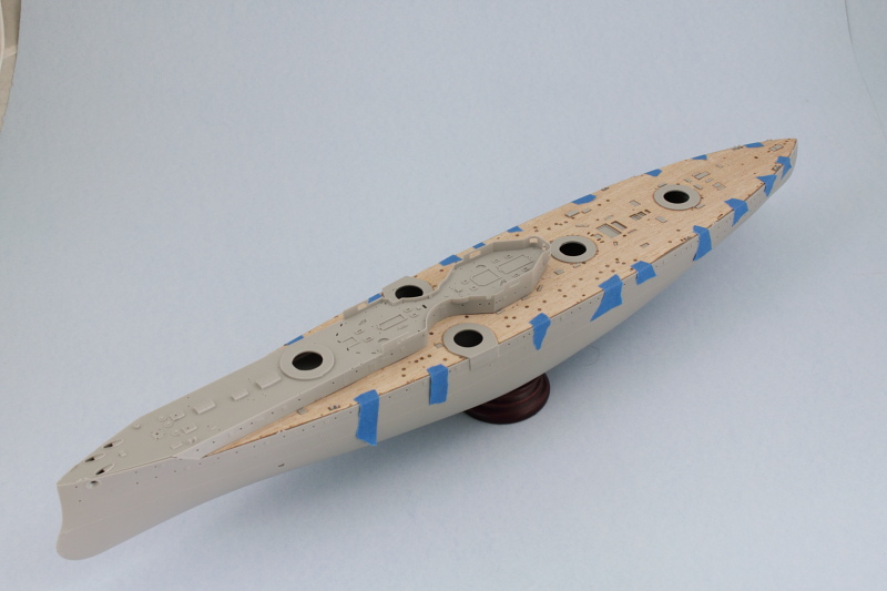
Second step in the hull painting process is complete. Careful masking over the black coat from yesterday and some MM Insignia Red produces the hull red portion.

After the bandages are removed, the patient seems to be doing just fine.

This will get the chance to sit overnight and then the fun begins with the gray top portions.
After the bandages are removed, the patient seems to be doing just fine.
This will get the chance to sit overnight and then the fun begins with the gray top portions.
-
Bill Plunk
- Posts: 1245
- Joined: Wed Sep 28, 2022 10:18 pm
WIP 08-13-2014
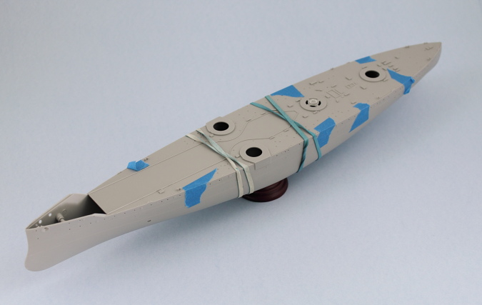
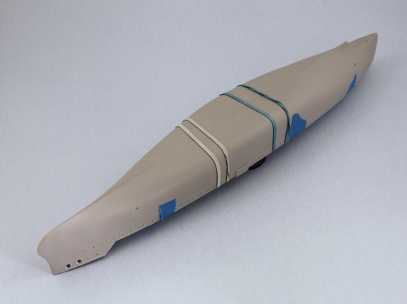
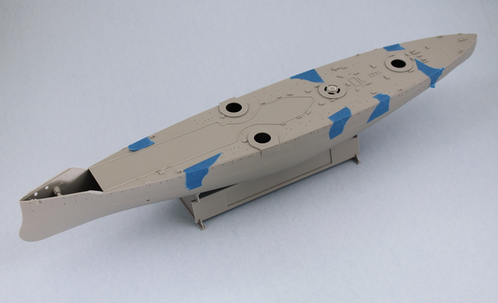
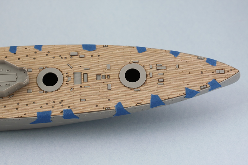
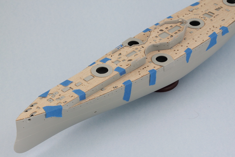
Last step in the hull painting gone done today. Applied a custom mix of roughly 70/30 Model Master Panzer Gray and Light Gray over the primer coat while leaving the boot stripe and hull red portions masked with blue painter's tape.

After that had dried, the tape came off and there were a couple spots that needed some touch-ups around some of the 'ribs' on the waterline, so I re-masked carefully with short strips where needed and either sprayed more gray or more of the Flat Black as the case required to tighten up the boot stripe.
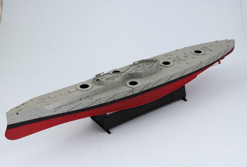
The sharp eyed will notice that one of the rudders is missing in the last photo...it came off during the painting session and has since been reattached. Now I have to decide whether to go ahead and permanently attach the wood decks or wait until later...decisions, decisions!
After that had dried, the tape came off and there were a couple spots that needed some touch-ups around some of the 'ribs' on the waterline, so I re-masked carefully with short strips where needed and either sprayed more gray or more of the Flat Black as the case required to tighten up the boot stripe.
The sharp eyed will notice that one of the rudders is missing in the last photo...it came off during the painting session and has since been reattached. Now I have to decide whether to go ahead and permanently attach the wood decks or wait until later...decisions, decisions!