Trumpeter 1/350 HMS Dreadnought 1907 (2014)

Bill Plunk
Posts: 1245
Joined: Wed Sep 28, 2022 10:18 pm

WIP 08-31-2014

Post by Bill Plunk »

I started in on the masts with the foundation of the tripod elements needing attention first. I left off the coaling derrick arm to allow more flexibility in its positioning for later and also to keep it out of the way of trying to install its host leg into position. Trumpeter designed it with a notch near the base that interacts with the boat deck level to install it in the correct position and having the derrick in place would make that much more frustrating than it should be. I airbrushed all three legs after adding in the little platforms to the two front legs and the searchlight platform to the rear leg. All three legs were installed into the super deck and then aligned where they all meet at the top. I left off the little PE support piece, PE33A, for the searchlight platform's underside until after things had set on the three legs to avoid the possibility of it getting knocked loose and lost to the carpet monster.

One detail that I noticed in the Kagero 3D book that was missing were the three triangular braces between the legs, so I used some 0.6mm styrene rod to recreate those. The front brace went in first, followed by the PE ladders for the little elevated platforms, then the rear braces were added. I also added the last two funnel stay lines that connected to the tripod legs to round things out there.

Image

Once all that had set up, I hand painted the braces and added the searchlight and railing to the platform. The derrick came next and I had to decide whether to position it as Trumpeter wanted it or how the Kagero book shows it in the 'stowed' position. The Kagero position would complicate a lot of things including the aft conning tower, the way the signal flag lines would be rigged, and also possibly interfere with the boats...so I decided simpler is best and put it in the Trumpeter designed angle. May not be 100% accurate but it's something I can live with.

Image

I also added in the access ladder, PE48A, for the front funnel that reaches from the super deck to the weather station platform. Had I known how tight that space would get at this stage, I would've installed it sooner but I had overlooked it in the instructions under Step 30.

Image

Next up will be the complex task of working on the crow's nest platform with all of its PE parts and the upper portions of the front masts and cross arms. Since those are going to be replaced with brass rod to take the strain of rigging, I've got to devote some careful study to that and decide how best to tackle.
Bill Plunk
Posts: 1245
Joined: Wed Sep 28, 2022 10:18 pm

WIP 09-01-2014

Post by Bill Plunk »

Hope everyone had a great Labor Day holiday! Efforts today certainly lived up to the 'labor' part at least but I had fun working on the main mast and its components.

I decided to replace the kit-supplied styrene mast-crossarm piece, C3, with brass rod to provide added strength and durability for this critical piece of the superstructure. My LHS stocks several different diameters of brass rod in their R/C aircraft section and I picked out different lengths of varying diameters and brought them home to see which would do the trick since the cross arms are thinner than the mast itself. I used a Dremel cordless tool and a cone-shaped grinder tool to introduce a taper for the mast but left the cross arms as-is given their relative thinness to begin with. Once I had the main mast done, I cut out the three cross arms again using the kit part as a guide for their length, and then marked their center points with a sharpie. Using a triangular needle file, I notched the main mast in the appropriate places so the cross arms would have a solid contact point.

Once all that prep work was done, it was time to solder the cross arms to the mast. I have a Weller variable temp soldering iron and while it was warming up, I used a piece of fiber board and some T-pins to position the mast and cross arms correctly. I used silver-bearing solder paste to place small beads over the join, the soldering iron provided the heat, and voil�! Brass mast and cross arms.

Image

Image

While I was at it, I also created the rear mast and cross arm combo for the aft mast. The third cross arm for the main mast integrates directly with the fire direction platform, so it was secured in place with CA gel separately from the main mast. This also makes life easier when attaching all the PE bits for the underside as the cross arm becomes a convenient 'handle'.

Image

Speaking of PE, the next steps require lots of patience and test fitting with the tripod to make sure the alignment is correct on all the underside supports for the fire direction platform. There are 5 separate parts and the locater marks that Trumpeter provides are a helpful guide but some adjustments are still needed to get the parts to line up correctly and play nice.

Image

If using the styrene masts, Trumpeter has you secure the mast to the platform before adding the rear bracket and rigging extensions. I did the reverse for handling reasons due to the added weight of the brass masts and also to create an added support structure for the mast itself. The rear bracket is made up of 5 different PE parts that all have to come together just so to create the right effect and the Trumpeter instructions aren't super clear on how they all come together. Fortunately the Kagero 3D book includes a very nice look at this area and helped greatly in terms of getting it all lined up properly.

Image

With that done, it was time to pair up the mast and cross arms with the platform. I flattened the rod with a square file so it could have a greater contact surface with the back of the platform and used CA gel to give me a little work time to ensure it was positioned at the right height and alignment with the third cross arm. Once the CA gel had grabbed hold, I used some Aves epoxy putty to stuff the base of the rear clamp structure so it would provide some greater stability and hold for the mast over the long term. A dry-fit test shows everything is lining up properly even though the angle on the camera isn't quite perpendicular.

Image

Not a bad day's work, the second mast should go faster now that I've learned the 'tricks' of the PE from doing the first one.
Bill Plunk
Posts: 1245
Joined: Wed Sep 28, 2022 10:18 pm

WIP 09-04-2014

Post by Bill Plunk »

More progress to report, this time in relation to the smaller aft mast and platform. After looking at all the parts involved, I decided to build up the platform and tripod first and allow that to set up nice and solid before adding the fire direction/control station and all the little PE that form up the mast brace and rigging points. A little bit of putty and sanding work was necessary where the two angled legs of the tripod join up together but otherwise everything assembled as designed. The Eduard set provided the railing for the searchlight platform. Then I attached the fire direction station box to the top of the tripod and let that set up. Unlike the main mast, this one goes a lot smoother this way in terms of getting all the PE parts to align properly vs. trying to puzzle piece them together separately. Once the station was firm, I used CA gel to add the mast after filing it's contact surface flat for better gluing. Last but not least, the PE stuff was added to build up the mast brace and rigging 'starfish' points. Just like with the main mast, some Aves epoxy putty was used to strengthen the connection between the mast and the clamp PE parts and will get the chance to setup hard overnight before it gets painted along with the main mast.

Image

Image

Image
Bill Plunk
Posts: 1245
Joined: Wed Sep 28, 2022 10:18 pm

WIP 09-05-2014

Post by Bill Plunk »

More progress on the masts front to follow-up from yesterday. First order of business was adding in the tall posts, parts D7, that Trumpeter has you add in Step 43. These need to go in before the rigging though so I added them now especially as they interact with two of the 'starfish' points. Roof for the platform was also added so it could be painted as a single unit for easier handling.

Image

The main mast got some final details as well in the form of the Eduard set. These rigging lines would be pretty tough to add using just the EZ Line given their curved shape and interaction with the other signal flag lines to be added. Since these are PE, I added them now so that the CA would have a metal-to-metal attachment point. Roof of the fire direction platform was also assembled

Image

Out came the airbrush again and, with the help of some locking tweezers, both sets of masts were painted.

Image

While hard to spot in the following pic, I used some MM non-buffing Metalizer Gunmetal to detail the curved rigging lines. Then the main mast was installed permanently atop the tripod and the roof added. I had to lightly sand the back edge of the roof so it would sit at the proper height/angle in relation to the mast as a minor adjustment.

Image

The rear mast element received its pair of search lights and was also permanently installed. I used regular glue for the base of the platform elements and some gap-filling CA for the tripod legs that install into the deck.

Image

All of that will get the chance to set up nice and solid overnight before I start adding the rigging. Due to the tight spaces involved, some decisions will have to be made on just which lines to add or leave out as I don't think there's quite enough room, particularly with the rear mast, to add all the lines that the Kagero 3D book and blueprints show as being used but I'll do my best under the circumstances.
Bill Plunk
Posts: 1245
Joined: Wed Sep 28, 2022 10:18 pm

WIP 09-06-2014

Post by Bill Plunk »

Spent a great deal of time working on the rigging today and was really impressed with the EZ Line, it truly lives up to its name in this particular application! After some careful study of the Kagero 3D close-ups and the rigging diagrams in the scale blueprints, I started in on the fore mast first. All of the interior rigging and bracing lines were done first and I generally worked my way from bottom to top one side at a time so I could get things as close to symmetrical as possible.

Image

Then the real fun began in terms of running the signal flag lines. I decided to run them as single lines only instead of doubling them up as the space is pretty crowded even with the single only. The connection points I had installed earlier proved very handy still as it made life a lot easier for attaching the bases of the lines and avoiding any tangling in the process. For these I started with the lowest cross arm first and worked from the innermost out to the ends, one side at a time, until I had the 6 lines done. Rinse and repeat for the 2nd cross arm.

Image

For the rear mast, the space tolerances are smaller but I followed basically the same pattern as on the main mast. I was able to get all the lines in place around the 'starfish' with a little patience and care. The rigging is now about 95% complete. While I won't be trying to recreate the cage-style aerials, I will run single representative aerial lines between the two masts and to the jack staff once it's installed but I'm deliberately holding off on doing that until I get the rest of the hull details done to avoid any snagging/complications in that process.

Image

Image

Rounding out the day's activity, I added the railing and optical range finder to the spotting platform and then installed it in place on the boat deck. The Trumpeter railing set included a piece that was just perfect as-is for my needs but these railings are more flimsy than the Eduard railings and will deform at the slightest opportunity, so shaping it into the correct oval shape was an exercise in patience for sure. Last but not least the remaining four coal derricks were painted and installed. For some reason, Trumpeter left out of the kit the horizontal derrick arms that should be at the front...I think they planned to include them since they had notches in the legs of the tripod where they should connect to...but no parts provided on any of the sprues in the kit. I had filled those notches earlier after trying to figure out why they were there...and now that little mystery is solved I think.

Image

Next up will be the repetitive joy of installing 50+ PE coal scuttle covers on the deck and starting to add in more of the remaining details there now that the rigging is largely out of the way.
Bill Plunk
Posts: 1245
Joined: Wed Sep 28, 2022 10:18 pm

WIP 09-07-2014

Post by Bill Plunk »

Today's update focuses on one of those less-glamorous aspects...dealing with lots of tiny parts in a repetitive process, but one that does add some nice detail to the deck when complete. Due to the Dreadnought's compartmentalized design for vertical access to areas of the ship vs. the usual horizontal water-tight door type of access, there are a ton of coaling scuttle points scattered all over the ship. 56 in total on the main deck plus another 4 on the super deck. Fortunately, the Wood Hunter set includes a nice PE fret with 60 of these designed specifically to fit the openings provided in the wood deck. A while back in one of my previous airbrushing sessions I took advantage of having the AB loaded up and applied some of the hull gray so it could sit and cure for a nice long while before I got around to installing them.

Image

Working one at a time, I used Gator Grip glue applied with a toothpick point into the openings and a 2nd toothpick (important not to mix them up!) moistened with spit to pick up and place the cover in position. Careful pressure with the point of a toothpick pressed it into place. Rinse and repeat 56 times and you have all the ports in place after a couple of hours, 28 on either side of the deck.

Image

Still more work to come in the detail department as I work on all the little odds and ends.

That's all for now, have to get ready to watch the Niners-Cowboys football game to kick off the 2014 season here in a bit.
Bill Plunk
Posts: 1245
Joined: Wed Sep 28, 2022 10:18 pm

WIP 09-09-2014

Post by Bill Plunk »

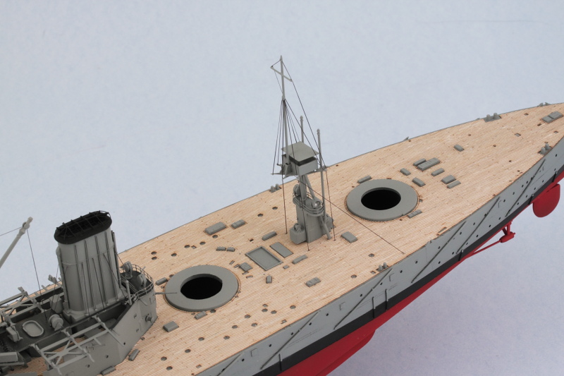
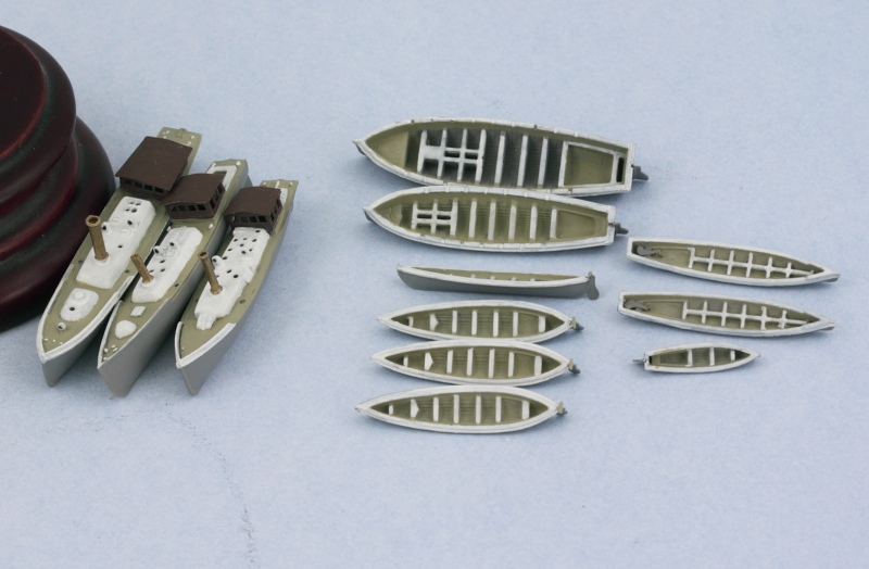
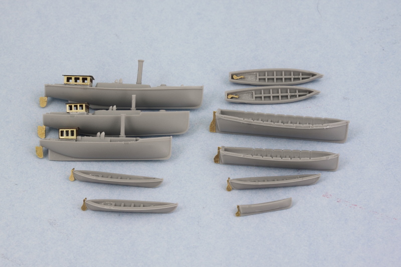
Last couple of rounds have focused on the ship's compliment of various boats. This is a little trickier than it might be otherwise because you have to kind of puzzle piece things together between what's in the instructions and what you actually install and where...but more on that in a moment.

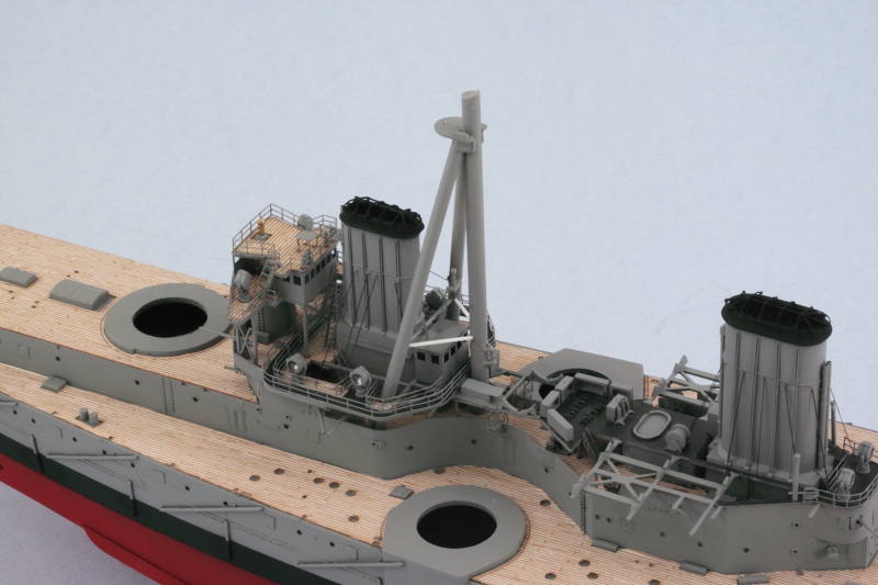
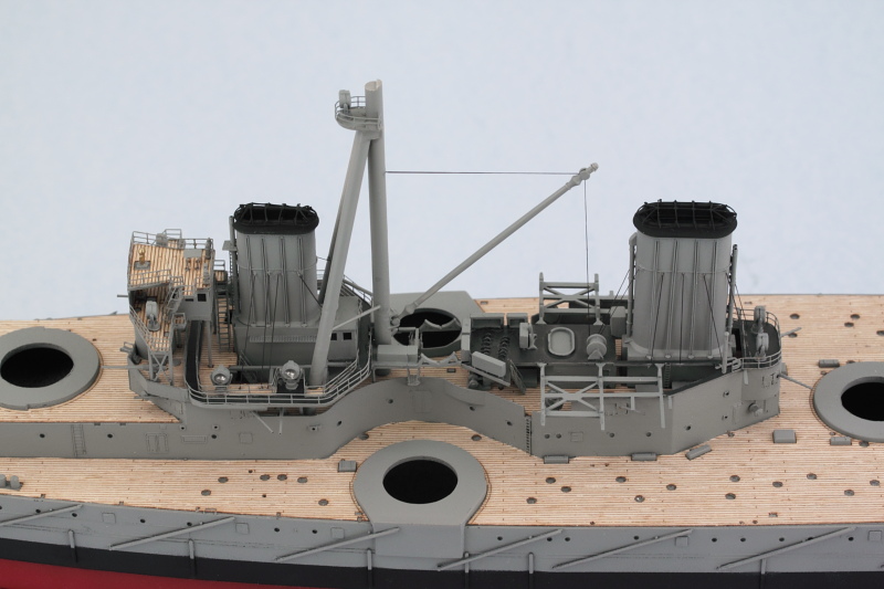
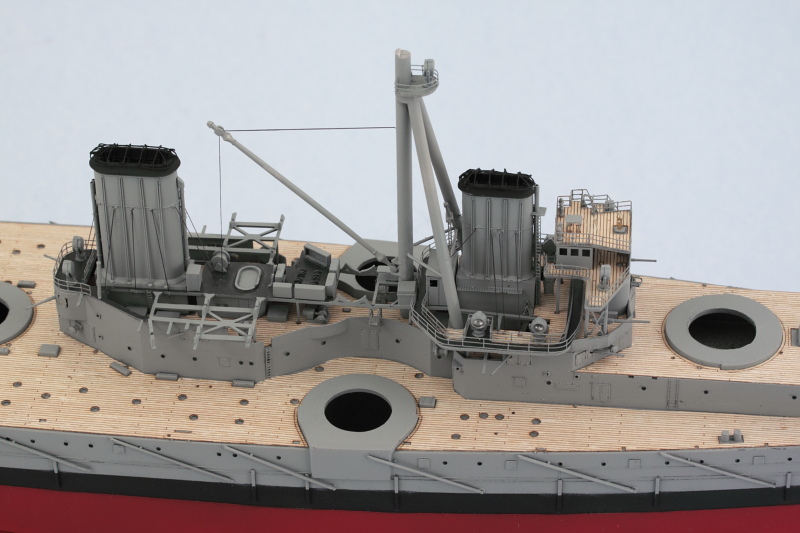
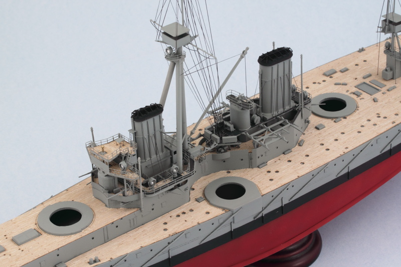
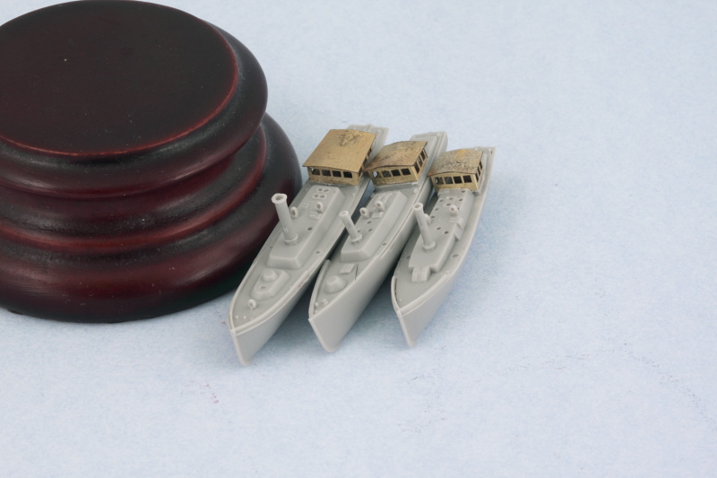
First order of business was improving some of the details on the three different steam-powered barge and pinnace craft. Trumpeter provides them as two part assemblies with the cabins molded solid (but hollow on the inside) as part of the upper deck portion. The Eduard set really improves the detail here by providing actual wheel-house/cabins with open windows, but that means surgically removing/cutting-down the molded on item so it can take its place.

Image

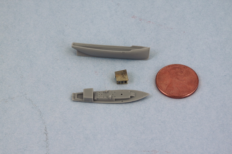
After careful surgery and some sanding, you can get a pretty good result between the two. I also improved the detail level by drilling out the air funnels and the smokestacks on each of the three boats along with the main cabin port holes.

Image

Now where life gets interesting is figuring out which of the kit-supplied oar-powered boats to use and where they will ultimately go. After studying the Kagero 3D reference photos, I figured out the following:

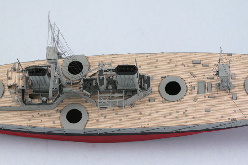
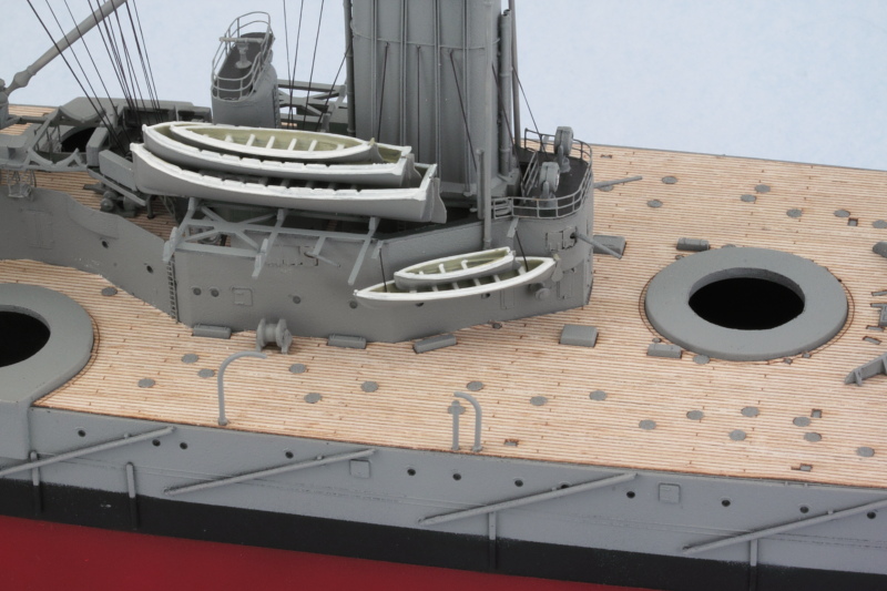
1) D43 are the 30 ft. gigs, and you need 2 of them, one on either side of the first funnel on the boat deck...but for them to fit, you need to not install the rudders and instead place them inside the boat itself as a stored item.

2) J1 isn't actually used anywhere even though the instructions have you assemble it...it's close in size to D43 but slightly longer...so it doesn't fit anywhere regardless.

3) D35 is the 16 ft. dinghy, you only need one of these and not the two that the instructions would have you build. The one you need will stack inside the port side suspended whaleboat.

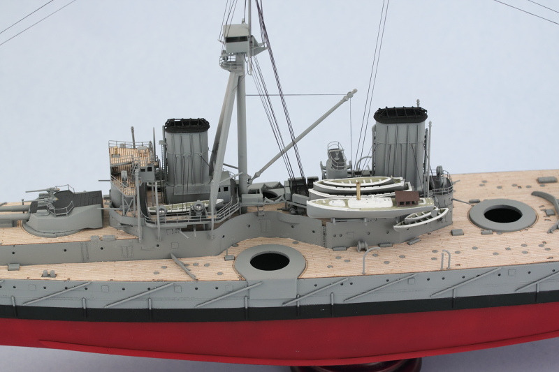
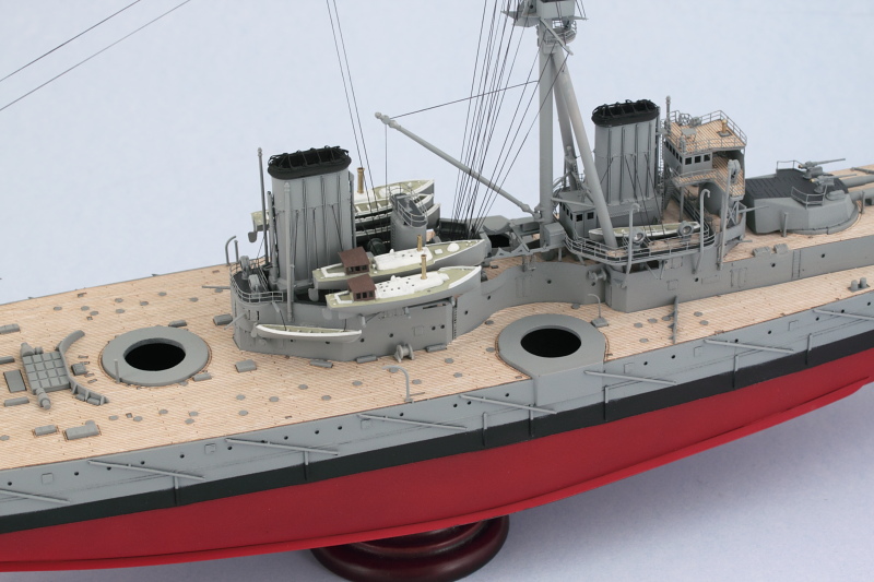
4) J3 are the 32 ft. cutter life boats...you need 3 of these (one in the middle of the boat deck and 2 for the davits at the front of the boat deck). Unfortunately, the kit only provides one for the middle...so I've asked my good friend Steve Reid at Celtic Werks to cast some resin copies from the kit part to fill this gap, as a result they are 'MIA' from the group photo below until the casting is done.

5) D3 are the 27 ft. whaleboats, the instructions want you to build 5 but only 4 are needed (one in the middle of the boat deck, the other two hang from supports at the rear of the boat deck, one nests in the three-stack of boats on the port side). Ignore the weird directions that would have you stack a whaleboat and dinghy on top of the port side steam pinnace, that's a Trumpeter invention as far as I can tell.

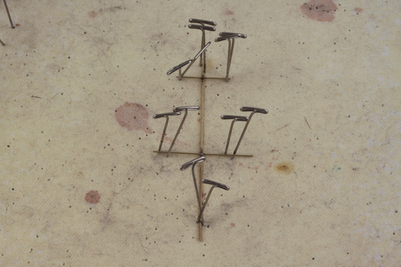
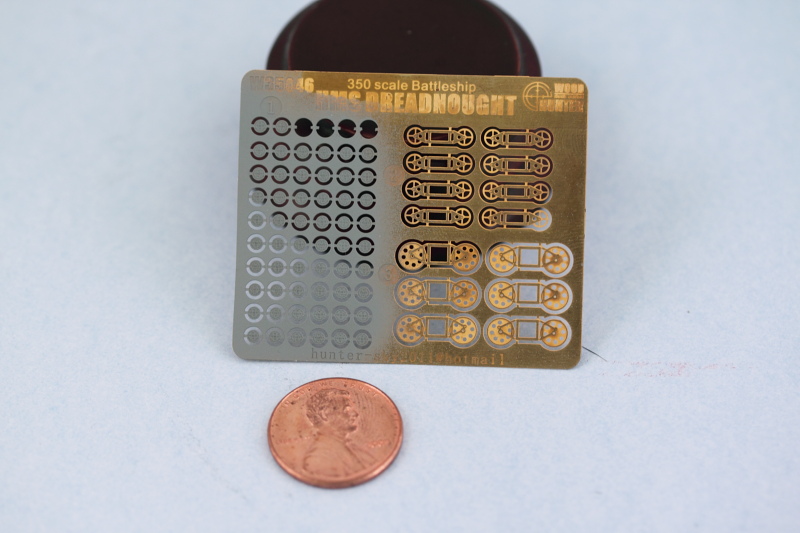
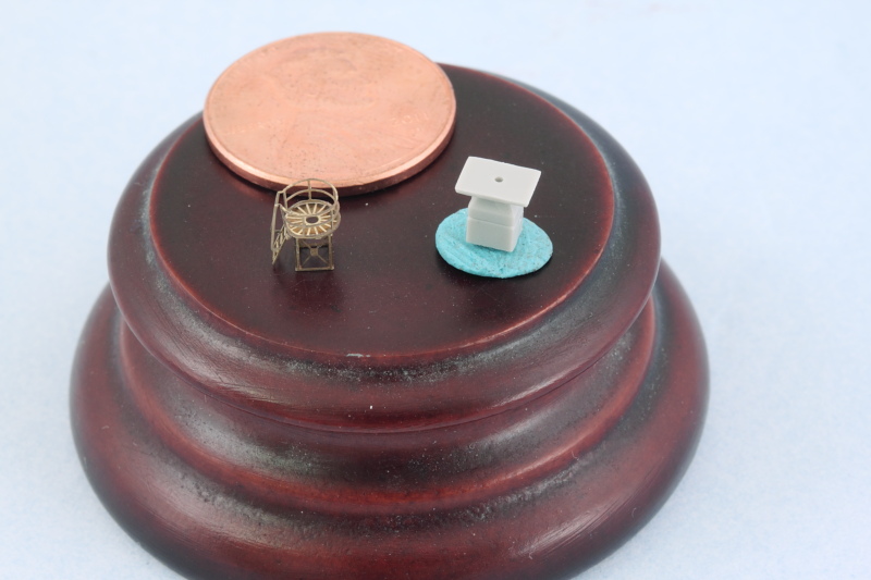
While the instruction steps never show them actually installed, the 2 whaleboats and the dinghy that suspend from the rear portion of the boat deck do show up on the finishing guide as does the pair of 30 ft. gigs, so if you're paying attention you can catch that at least. All of the boats received their PE rudders in anticipation of some airbrush attention to lay down a base/primer coat of hull gray before they get further hand detailed.

Image

Tomorrow will see the boats get further detailing so they can be ready for installation.
Bill Plunk
Posts: 1245
Joined: Wed Sep 28, 2022 10:18 pm

WIP 09-10-2014

Post by Bill Plunk »

More progress in the boat department, we have paint! I airbrushed the hull gray color so that it could do double duty as both a primer for the detail areas and PE parts and provide the main external color for the boats. The detail work was all done with the aid of an Optivisor and a 10/0 pointed brush. Flat White for the trim, a mix of 50-50 Dunkelgelb/Light Gray for the wood areas, and Italian Dark Brown for the steam boat wheel houses. To add a little variety, I applied some non-buffing Metalizer Brass to the smokestacks to round things out. Not a lot in terms of number of pics but a full day's effort to get the detail painting done.

Image

Next up will be placing some of the boats and continuing to work on the remaining main deck details.
Bill Plunk
Posts: 1245
Joined: Wed Sep 28, 2022 10:18 pm

WIP 09-12-2014

Post by Bill Plunk »

Latest progress has lots to report on multiple fronts. First up were all the bow super-deck details. I used the Trumpeter-supplied copper anchor chain and painted it with Model Master non-buffing Metalizer Gunmetal applied by hand. For the two non-fitted 12 pdr mount plates, I cannibalized a couple of the spare guns on the sprue and clipped off their bases, gluing them in place with CA gel then sanding them smooth and painting them in place. Anchors were installed along with the stove pipes, small cranes, and the turret breakwater. Then the A turret was carefully placed as all the other small details now prevent it from being able to rotate, so it had to be dropped in place vertically at an angle so the rear of the turret would clear the connecting stand to the superstructure. Last but not least I added the jack staff and angled PE brace for it.

Image

Image

With that out of the way and time to install the boats, I added the last remaining piece of rigging by running aerial lines from the bow to each of the masts as well as connecting lines down into the boat deck roof of the wireless room.

Image

Speaking of the boats, I started on the port side first since it has the most boats. The three-stack was assembled and installed in place followed by the suspended whaler and dinghy combo. For that combo, some EZ line was used to represent the suspended rail/rope combo that holds it up.

Image

Rounding things out on this side, the steam pinnace was installed. The 30-ft gigs were added as well to both sides of the forward funnel and then the life boat davits added. Other small details like the wing turret break waters and the small mid-ship cranes were also installed.

Image

Next up will be the starboard side boats before moving aft to continue with the remaining details there.
Bill Plunk
Posts: 1245
Joined: Wed Sep 28, 2022 10:18 pm

WIP 09-13-2014

Post by Bill Plunk »

Work continued on the remaining details. As promised, first up were the starboard boats getting installed in place on the boat deck.

Image

With that done, attention turned to the remaining details on the stern. One of those is the compass stand and I have to admit that the difference here between what Trumpeter provides and what should be there (which the Eduard set does cover) is miles apart. The Trumpeter part is on the right while the Eduard multi-part PE replacement is on the left. I'm sure it's no surprise which one I went with!

Image

The Eduard set also provides caps for all the bollards, so those were installed and painted to match the posts. Small hoist cranes and stovepipes were added where needed and the X and Y turrets installed in place.

Image

Last but not least, the stern received the previously mentioned compass stand, 2 of the 3 12 pdrs, and the flag pole with its PE brace and small extended access stand. The kit-supplied access stand was just a simple piece of straight PE, so I used the Eduard piece instead to replace it. The third and final 12 pdr gun was left off so I could install the railings without having to fight with it since the barrel extends out over the rail and will be added later.

Image

Not a whole lot left to do. Essentially just the railings to add along with the retention arms for the torpedo nets that stick out under the railings, will add those after the railings of course.
Post Reply