Trumpeter 1/350 USS Texas BB-35 (2015)

Bill Plunk
Posts: 1245
Joined: Wed Sep 28, 2022 10:18 pm

WIP 09-22-2015

Post by Bill Plunk »

So after doubting the look of the 20-B yesterday, I did a little digging and came across this handy little color chart over on Cybermodeler. http://www.cybermodeler.com/color/usn_matrix.shtml

Now I know that digital color matching is always a kind of fool's errand, but I compared what it had on my monitor with how the Testors 20-B looks on the deck and it's a pretty close match. I decided to give it a small nudge in the blue direction using Ammo's Blue Filter for Dark Grey. I sprayed it as a mist coat through the airbrush and it altered it just enough to match I think.

Image

With that out of the way, I settled in for a long session with the Optivisor and the detail brushes to apply the haze gray to all the gun tubs and other details that needed it by hand.

Image

Next up will be installing the decks to the hull and then the fun of dealing with the upper decks and superstructure can commence.
Bill Plunk
Posts: 1245
Joined: Wed Sep 28, 2022 10:18 pm

WIP 09-24-2015

Post by Bill Plunk »

Major step forward today as I returned to Step 2 in the instructions. I got the main decks installed but before I did that, I did one last little step to help bring out the detail. I dry-brushed some medium gray that I keep around for this kind of thing to the various hatches and other bits that got the deck blue treatment to help add just a little bit more depth to the deck. I started with the stern deck first since it has a little support ledge that the bow deck sits on. No rubber bands needed since I had worked with the spreaders earlier to get just the right fit for both decks. Careful application of some Mr. Cement liquid glue and both decks are now a permanent part of the hull. Once they had set up, the bulges that create the elevated 5-inch mounts was added next.

Image

That allowed me to move on to Step 5 and start work on the 02 Deck level. As instructed, I removed some molded on detail that isn't needed and also opened up the required mount holes for some details that will get installed later. I did make one small mistake as the diagram pointing out which holes to open up is small and I accidentally opened up one hole that wasn't needed. Filled it back up with putty and moved on. The area with all the gun tubs needed a lot of sanding attention to remove mold seams that show the limitation of the molding technology used I guess. They weren't huge but were in some tight spots. Sanding twigs and sharp knife point had to work together to get rid of them.

Image

The instructions show the two deck components plus the B turret barbette all going in as a single module. That would probably work but when I test-fitted them, the gun tub part has a slight warp/flex to it that is going to require some special attention when I attach it so that it lines up properly. That plus the elevated nature of the barbette means it's going to be easier to paint the different haze gray and deck blue areas if I keep the three parts separate for now.

Image

Next up will be getting the 5-inch guns done and fitted with their brass barrels before I sling some more paint on the 02 level.
Bill Plunk
Posts: 1245
Joined: Wed Sep 28, 2022 10:18 pm

WIP 09-25-2015

Post by Bill Plunk »

The Master barrel set includes turned brass replacement barrels for the 5-inch guns and initially I thought there was some mistake as they are substantially longer than the kit parts. However, once I placed the kit parts and then compared the barrel protrusion length to the reference photos, it was obvious that the kit parts are both too short and too thick. So out came the sprue cutters to remove the kit barrels. I used a #76 drill bit and CA gel to fit the brass barrel after some careful sanding and trimming to preserve the recoil housing detail.

Image

As I worked on each gun, I checked their fit and angle alignment on the gun deck. The angles needed are slightly different in the three different mounts so that they will properly clear the edge of the bulge.

Image

The first step in getting the 02 deck level ready for installation involved airbrushing the Deck Blue where needed. Since I had cleaned up the 03 deck to see what areas it would cover, I went ahead and airbrushed it at the same time.

Image

Next up will be getting the Haze Gray on so I can go ahead with the 02 deck install along with the 5-inch guns.
Bill Plunk
Posts: 1245
Joined: Wed Sep 28, 2022 10:18 pm

WIP 09-26-2015

Post by Bill Plunk »

Some days the progress is measured in terms of inches. Today was one of those days, mostly due to all the masking that was needed for the gun tubs on the 02 and 03 deck levels. Following up from yesterday's Deck Blue session, today was all about the Haze Gray. I spent more time masking than I did actually painting, that's the way of it for this kind of paint scheme!

While I was at it, the B turret barbette and the 5-inch guns also got their turn with the airbrush.

Image

Once all the masking was removed, some small touch-ups were needed with the Deck Blue. Easily taken care of courtesy of the Optivisor and a pointed 10/0 brush.

Image

Next up will be the actual installation of the 5-inch guns and the 02 deck.
Bill Plunk
Posts: 1245
Joined: Wed Sep 28, 2022 10:18 pm

WIP 09-27-2015

Post by Bill Plunk »

Focus for today was getting the 02 level deck installed. I had airbrushed some Haze Gray in the recessed areas as a precaution even though very little of it is actually visible once the deck is in place. Exposed portions of the bulge top were painted Deck Blue and the 5-inch guns installed at the desired angles. The base of the 02 level was also glued into place first so I would have a solid foundation to work from to correct the warp issue mentioned earlier.

Image

The actual 02 deck is a tight fit with the hull bulge so that helps correct some of the warp but not all of it. I used regular glue to give me plenty of work time and pressed the deck in place starting at the rear and working towards the bow. A rubber band and a pair of compression clamps helped things along as well. Once the glue had grabbed a bit, I added the B turret barbette to help hold things in place.

Image

After the clamps were removed, I decided that I wanted to do something besides use the kit-supplied base to display Texas when she's built. A quick trip to Lowe's and I found some excellent copper knobs that are perfect. That meant I needed to drill some holes in the hull to take their mounting screws. As a result of the drilling, the hull separated a little, so I dosed it with some liquid glue and the clamp once more to solve that little problem.

Image

After a couple of touchups in some spots, the 02 deck is now on. That completes Step 5...out of 37...still a long way to go! ;)

Image
Bill Plunk
Posts: 1245
Joined: Wed Sep 28, 2022 10:18 pm

WIP 09-29-2015

Post by Bill Plunk »

Steps 6 through 9 deal with the superstructure elements that build up from the 02 deck and around the forward tripod mast. Most of the day was spent cleaning them up and dealing with various seams, ejector marks, and checking the fit relative to each other to ensure everything played nice.

I did find one small problem, the hole in part M15 that is the last element that the main forward leg of the tripod passes through before contacting the 02 deck wasn't big enough for the tripod leg to pass through. It needed to be slightly wider, so a quick session with a round needle file did the trick. It would've been extremely difficult to fix if I had already attached it per the instructions in Step 6, so glad I caught it early. I also checked all the other openings that the different legs have to pass through and none of them had any issues.

I left off the different PE bits that attach in delicate spots for the time being since I need to handle them quite a bit still for painting and something would be sure to get knocked off and lost in the process. Just the law of averages with that kind of thing! I did attach the two small side platforms that go on the conning tower even though they aren't mentioned until Step 11. It just makes more sense to have them on now for painting vs. adding later.

Image

Not all of the areas in the superstructure have Deck Blue areas, so after checking the reference photos, the appropriate ones were singled out and given a dose courtesy of the airbrush.

Image

That means as you might have guessed, more fun with masking tape to come! ;)
Bill Plunk
Posts: 1245
Joined: Wed Sep 28, 2022 10:18 pm

WIP 09-30-2015

Post by Bill Plunk »

After masking off yesterday's Deck Blue effort, I airbrushed the Haze Gray on all the different superstructure components. Once that had dried, I set to work getting the three different levels together. The instructions would have you install the conning tower level to the 02 deck in Step 7 but it's a lot easier to add its details and check the fit with the upper superstructure if it's left free standing, so I held off on that for now. I did go ahead and assemble the conning tower deck components together as called for in Step 6 and added the railings and ladders from Step 9 as well. I'm using something new for these delicate PE parts, Gator Grip Thin Blend, and so far I'm pretty happy with the results.

Image

The upper superstructure components were assembled next as directed in Step 8 with the exception of adding the support legs for the level directly above the conning tower. Since there's a lot of complex railing that goes around the back edge, I wanted to be able to work with it as a relatively flat structure first to shape them correctly. Those aren't called out until Step 14 so it definitely pays to be looking ahead on all these areas.

Rounding out the day's efforts, I added all the little tiny detail bits called for in Step 11. Again, it's a lot easier to do that now with the decks loose vs. when they are all stacked together and installed, so I took advantage of the opportunity.

Image

Image

Next up will be spending a lot of time with the railings to get them into shape before stacking up the superstructure.
Bill Plunk
Posts: 1245
Joined: Wed Sep 28, 2022 10:18 pm

WIP 10-02-2015

Post by Bill Plunk »

The latest round of effort focused on the superstructure deck above the conning tower. It's got the most complicated railing situation and my decision to work on it without the support legs in place was a sound one. It took a lot of careful effort to bend the railings called out in Step 14 into shape and I used a combination of pointed tweezers and round rolling objects including a paint brush handle, my Xacto handle, etc. to get it done. Definitely an exercise in patience and not one I would recommend trying to do with the decks already attached together as the instructions would have you do it.

The railings were hand painted off the deck first then installed with small amounts of CA glue since they have some tension due to their unusual shapes and touched up where needed post-install. For the slightly raised forward area, I had to file down the edge that overhangs so that the railing could clear in that spot as it's slightly too low. I also added the access ladders and the fire direction stations as called for in Step 12. There's a small error in the instructions in Step 14, the small railings are PE-B10 and not PE-B9 as called out since those are already used on the conning tower deck level below this one.

Image

With that out of the way, I could return to Step 8 and fit the support legs and little PE lattice structure that I had skipped earlier. This turned out to be an extremely finicky arrangement that was a bear to get lined up properly. This was mostly due to the fact that the two single legs have a finned portion that's supposed to line up with the paired legs but which is slightly too wide to do that and allow the legs to sit square with each other. Once that was taken care of, it was a case of getting all four legs to sit in the proper alignment with their slots in the conning tower deck and not twist in the process. It turned out that my decision to add the two ladders that sit right next to the legs was a mistake and they were removed so I could have enough room to adjust the legs as needed. Currently, the two decks are only dry fit together as I don't want to commit to glue until I'm sure that the three tripod legs are going to play nice with all the deck levels.

Image

Next up will be dealing with the third level's railings which are only slightly less complicated than the deck I worked on today. :)
Bill Plunk
Posts: 1245
Joined: Wed Sep 28, 2022 10:18 pm

WIP 10-03-2015

Post by Bill Plunk »

Round 2 on the superstructure's railings was taken care of today. These are called out in Step 15 and the rear railing has a gull-wing shape to it that was a challenge to get shaped since the little middle part isn't truly square, it's slightly angled at the sides. No sooner would I get one side lined up then I would have to adjust the other side and so on until I finally got them both lined up and curved just right.

Same drill as before, the railings were bent to shape first, then hand painted, and installed with small amounts of CA.

Image

The three levels stack up nicely together, I'll add their connecting ladders once they are permanently joined together along with the tripod masts. This is just a dry fit so I could check the tripod masts. Test fits with the mast poles shows that everything lines up fairly close, but it will still be a complicated matter to get them all sitting properly as a single unit. While not pictured, I've already hand-painted the masts to get them ready for primetime in the next round of effort.

Image
Bill Plunk
Posts: 1245
Joined: Wed Sep 28, 2022 10:18 pm

WIP 10-05-2015

Post by Bill Plunk »

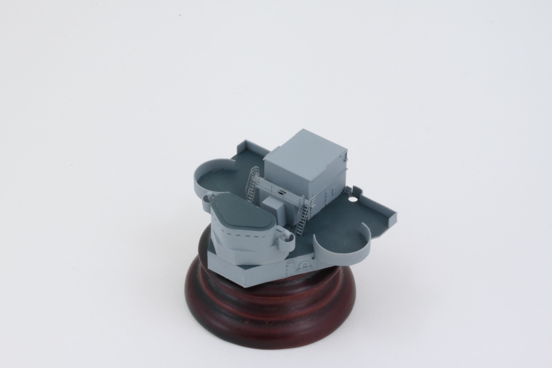
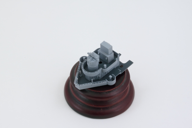
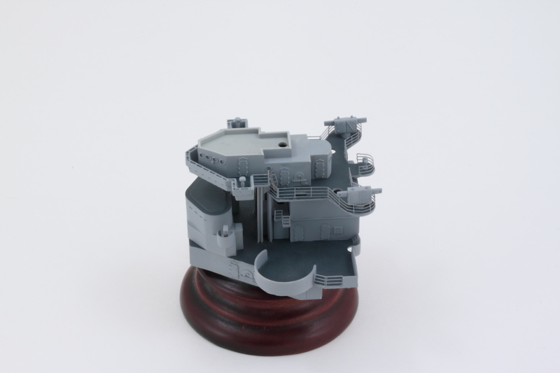
Today's efforts was a moment of destiny, sort of! It was time to get the main superstructure levels together and all of the ladders connected to create the three-level structure as an integrated unit.

First up was the main bridge level above the conning tower. I started by permanently gluing it down using the tripod masts and the deck level above it to ensure everything lined up while the glue set. I went to work on the ladders that connect up to the bridge deck and quickly realized that the openings in the bridge deck are too narrow for the ladders to fit...so some careful sanding with a square needle file was needed until the openings could take the ladders. I also ended up removing temporarily the little side railings (parts PE-B20 from Step 9) as the ladders couldn't quite fit over them and some adjustments were needed. So much for that effort previously! :) 
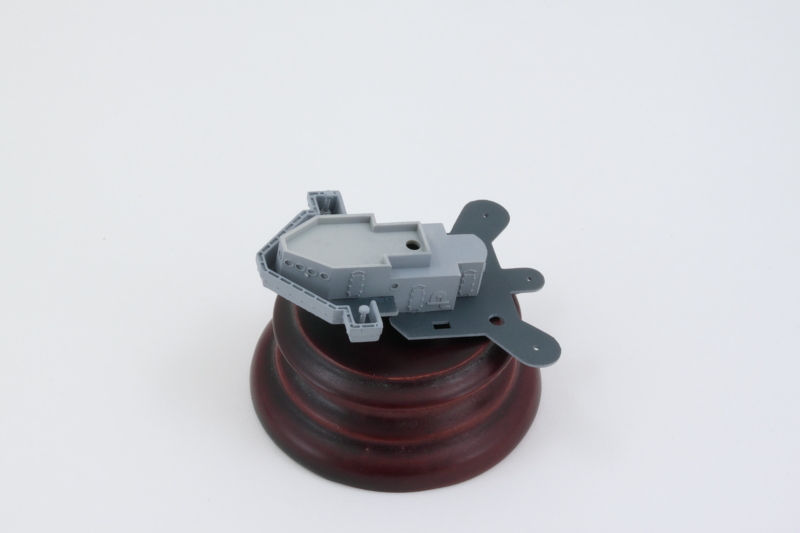
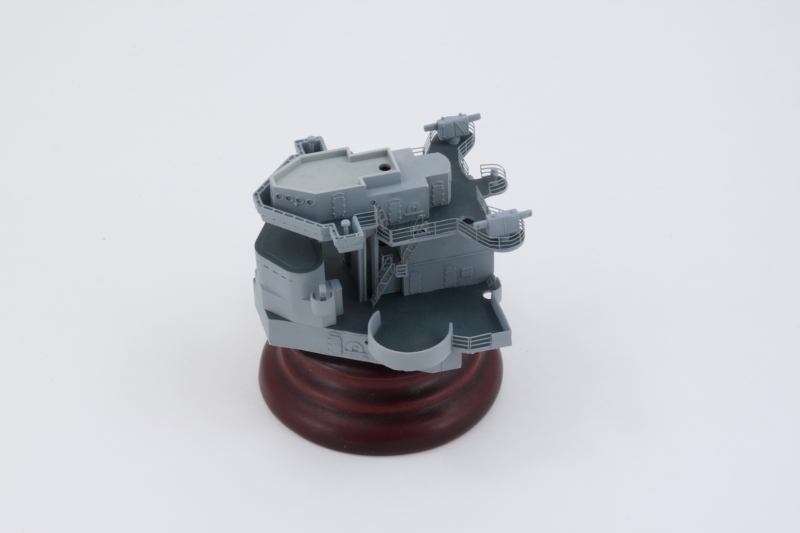
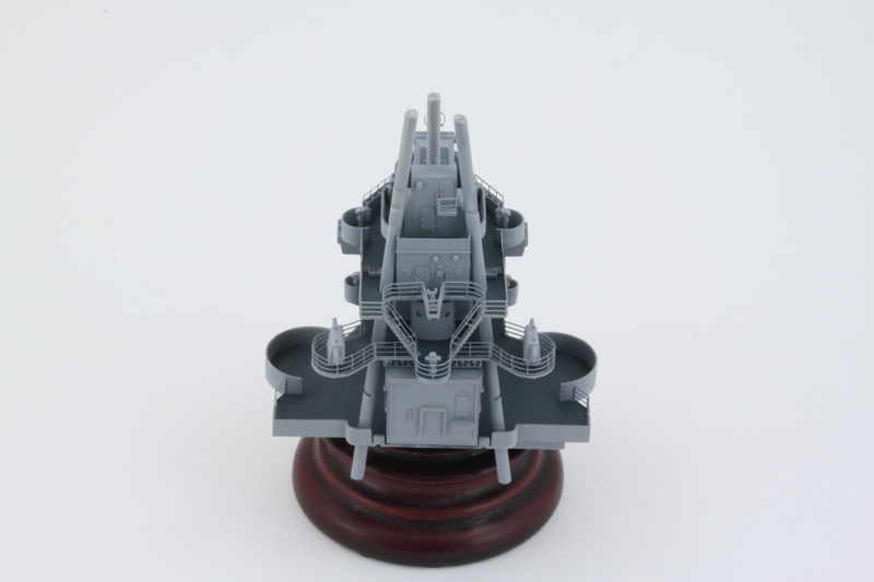
The bottom level ladders and railings were re-installed now that the bridge support legs were in place to complete the process of joining these two levels.

Image

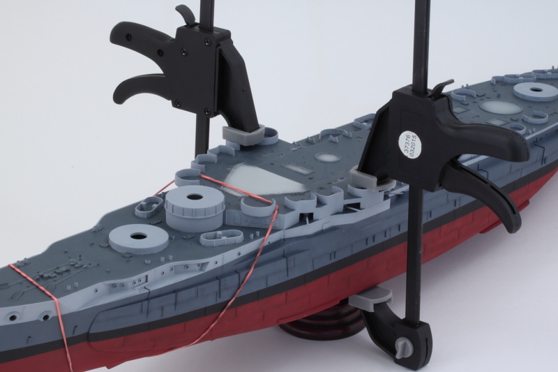
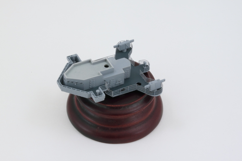
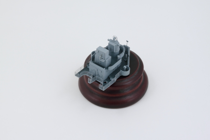
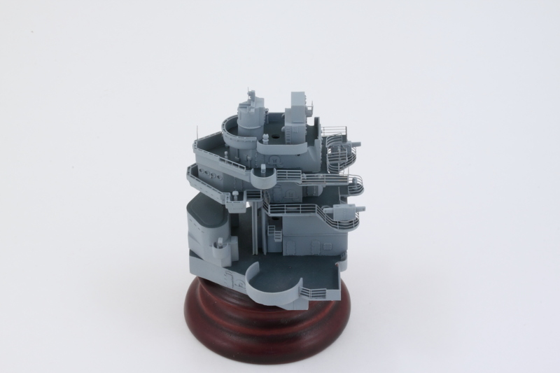
Now came the really fun part, adding the third level above the bridge deck. Test fits with the tripod legs showed that the front leg was causing the deck to want to tip up at the front and create a gap with the level below. This is due to the fact that the front leg doesn't install straight down but is slightly inclined and by the time all the levels are stacked up, it puts some tension on the top deck. To correct that, I used a round needle file to slightly enlarge the opening. I added the triangular supports for the little deck extension that was originally called for in Step 8 and then installed the top level into place. Some slight finger pressure at the front was needed until the glue set. Once it did, friction and the angles involved is holding the tripod legs in place as they haven't yet been glued down since they still need some details added to them in steps to come.

Image

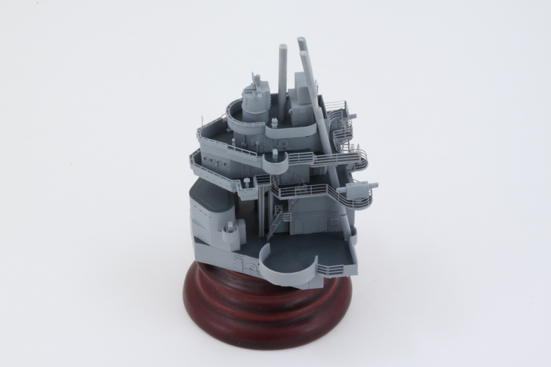
Rounding out the day's efforts, the two long ladders that connect the rear areas of the two decks were added. These are very tricky as the contact surfaces are tiny and both ladders are in a very tight space and you can only place them after the two deck levels have been joined. Some Gator Grip Thin Blend glue gave me enough work time to get them in place. It's worth noting that the instructions tell you to install the same ladders twice, once in Step 14 and then again in Step 16! :)

Image

Next up will be taking care of those tripod leg details.
Post Reply