Trumpeter 1/350 USS Texas BB-35 (2015)

Bill Plunk
Posts: 1245
Joined: Wed Sep 28, 2022 10:18 pm

WIP 10-23-2015

Post by Bill Plunk »

Building on yesterday's work with the 40mm guns, I painted up the 3-inch guns and got them ready for installation. All 12 sets of guns were installed into their respective tubs and then the final set of PE railings and access ladders added for the 02 deck. The railings aren't called out until Step 28 vs. the guns going in under Step 22. In hindsight it would've been a lot easier to install the railings, particularly those with bends, between the tubs if they had gone in first vs. the guns but either way is still possible. Having the guns in place just means that there's a lot less room to maneuver around with the tweezers when it comes to placing the railings into some of those really tight spaces.

Image

Image

Next up will be dealing with the bow area details including the anchor chains.
Bill Plunk
Posts: 1245
Joined: Wed Sep 28, 2022 10:18 pm

WIP 10-26-2015

Post by Bill Plunk »

I've been slowly working my way through the bow details that are called out in multiple steps in order to get things squared away in this area of the ship before moving aft where the lion's share of stuff remaining awaits.

First up was returning to Step 19 and all of the little details there that I hadn't yet installed. The 12 tie-off cleats are something to watch out for as the instructions would have you fit them flush to the edge of the hull. The potential issue/problem with that is the railings that need to install there in the final Step 37 don't have any cut-outs in them for the cleats, so you're faced with one of two choices. You can fit the cleats flush and cut out the railings (which are provided as one single long piece for the complex curves in this space) which may or may not cause structural issues in the process or leave a small edge so the railings can install around them. I opted for the latter as that will also allow me to make cuts if practical later when the time comes.

The kit provides some nice copper chain for the anchor chains but the instruction diagrams are a little funky to say the least in showing how they should actually sit. I painted the chain as a single long length with Flat Black and then clipped one link at the end in half so I could use that to anchor it around the capstan and into the well with CA. The chain was run forward into the hawse holes in the deck instead of just ending abruptly as the diagram shows and a little more CA used there to secure it taught in place. Rinse and repeat for the 2nd chain. The length provided is plenty long enough and I still ended up with a couple of inches worth to spare. The PE grates were added over the top of the chains, but you can still see the chain if you look down through them.

Last but not least I added the 4 20mm guns into the tubs from Step 22 and the 4 floater net baskets on the B turret from Step 28. The baskets need to set just so to allow the back of the A turret to clear them so I did a quick test fit with one set of the turret parts just to make sure that wouldn't be an issue later on.

Image

Next up will be starting work on the 2nd half of the hull and all of its remaining goodies!
Bill Plunk
Posts: 1245
Joined: Wed Sep 28, 2022 10:18 pm

WIP 10-27-2015

Post by Bill Plunk »

As I was working on getting the different elements ready that go on the rear half of the main deck that need Deck Blue, it occurred to me that the turrets themselves are the largest remaining component that also falls into that category. I decided to test out what the best way would be to use the Master aluminum barrels and see how the turrets should be handled in the process.

The Master barrels have a short mounting pin on their bases and their length is designed to incorporate the little round base and pin arrangement that Trumpeter designed for the kit's guns. I had thought that I would need to use some lengths of sprue to achieve that and ensure the barrels would align properly, but that isn't the case. Instead, careful removal of the plastic barrel and drilling out the base to take the pin is all that's required. The key is to make sure that the barrels, as a pair, work together in terms of total length and spacing. I did need to use a round needle file tip to enlarge the little mount holes for the rod so that the guns would sit deep enough in the openings and not interfere with the fit of the base.

Image

Using the same turret parts that I had used to test the floater net basket arrangement previously, I did a quick mock-up to make sure this arrangement would work as intended. The turret and its base are only dry-fit for this test. I had also drilled out the holes and test fit the 20mm AA platform that goes on top of two of the turrets, in this case the B turret.

Image

Since I was in test mode, I went ahead and did a mock-up of the A turret as well to see how the pair would work together in the bow turret barbettes. The real trick will be painting the barrels and the turret components to fit in with the Measure 22 scheme. To that end, all of the turret components including the barrels themselves aren't attached to anything just yet. I did mark the barrel pairs so that I could be sure to keep them together per turret and I think I'll tackle them 2 at a time to avoid any problems/confusion vs. trying to do all 5 in one go...especially since the C turret has the float plane catapult as an added unique feature!

Image

Always an important milestone when you can see the big guns start to come into play! :)
Bill Plunk
Posts: 1245
Joined: Wed Sep 28, 2022 10:18 pm

WIP 10-29-2015

Post by Bill Plunk »

Continuing on from last time, I worked on the D and E turrets for the stern. Same drill as before when it came to getting the barrels replaced and paired up. The only minor complication with these two was also dealing with the base of the D turret as it too has yet to be installed permanently in position. The assembly for the 4 'normal' turrets is all dealt with in Steps 30 and 31 and one of the things it asks you to do is add 2 of the Carley float/rafts to the sides of either the A or the E turret without really saying which, but it's for the E turret. In a kind of funny inconsistency, the instruction diagram in Step 35 shows it with only one per side but Step 37 shows it with two! Reference photos show that at different times in her service life there was one and then later two, so you can take your pick! :D I left them off for now and will add them later after I've minimized the amount of handling they need to avoid the possibility of knocking them off and losing them.

As I mentioned before, the mid-ships C turret is a special case due to all the other stuff that goes in that area along with the seaplane catapult so it will be dealt with later.

Image

I applied some small amounts of liquid glue to the barrels where they join with the plastic mount rod inside the turret and let that set up with the turrets in place on the hull. Once I was satisfied that the barrels would stay together and keep their spacing, I marked each one so I could reunite it with the correct turret later on and then airbrushed a primer coat of MM enamel Italian Dark Brown onto the aluminum barrels. Why a primer coat you might ask? The barrels were included in the Measure 22 scheme with their top halves Deck Blue and the bottom Haze Gray, so I want to be sure that I can do that without running the risk of having paint lift off and/or chip and expose bare shiny metal when it does. Fingers crossed that my plan works!

Image

While the barrels were drying, I cleaned up and got all the stuff that goes into the aft tripod mast structures ready for a dose of Deck Blue. These are called out in Step 33 and Step 34. The top structure, part D9, is supposed to have a mount hole in it to take the radar antenna support mast but the part is molded solid. The diagram shows the hole present but it simply isn't there, so I lined it up with the matching hole in D8 and drilled it out with a small bit in a pin vise and then carefully enlarged it further with the tip of a #11 blade and a round needle file until the mast would fit properly. Since I was already slinging paint, I also got the structures from Step 24 that install on the main deck included in the program.

Image

You know what this all means...more masking before I can give them all the missing Haze Gray treatment! ;)
Bill Plunk
Posts: 1245
Joined: Wed Sep 28, 2022 10:18 pm

WIP 10-31-2015

Post by Bill Plunk »

Nothing like the trifecta combination of a Saturday, Halloween, and DST changing to create the perfect opportunity to work at the bench! :)

I spent most of the session masking off the Deck Blue so I could apply the Haze Gray to all the stuff I prepped last time. It's worth it though in terms of the end result it produces. The hardest thing of all was masking off the barrels as I knew it would be. I ended up using two 1mm wide strips on either side of each barrel vs. trying to use just one strip as the taper and step in the barrels makes it really hard to get a straight line otherwise.

Airbrush did the trick with the Haze Gray to get things to this point.

Image

That meant I could focus on getting the 4 turrets together now that all the different components were painted. The added fractional mm from the paint layers was just enough to provide a good friction fit for the metal barrels so I had to be gentle in coaxing them into position and then gluing them in place inside the turret. Bases were added next and then the 20mm AA platforms for the B and D turrets.

Image

I did a test fit of the turrets in their desired locations and made some small adjustments to the barrel heights so that they had a slight elevation and sat level. They will get the chance to sit in place overnight to be sure everything is nice and solid before I add the floater net baskets and 20mm guns to the B and D turrets.

Image

Image

Happy Halloween everyone! :)
Bill Plunk
Posts: 1245
Joined: Wed Sep 28, 2022 10:18 pm

WIP 11-02-2015

Post by Bill Plunk »

After much careful deliberation on what to tackle next in the grand scheme of things, I decided to spend some time on the aft tripod mainmast assembly that is dealt with in Step 33. This is a complicated affair and involves a lot of pieces, including the tripod legs, that have to interact perfectly for it all to come together as intended.

With that in mind, I decided to tackle the most difficult part of the whole thing, the one-piece railing that goes around the 2nd level deck. The instructions would have you add this after the deck was added to the little tower section that supports everything but that's not a really good idea. Especially since the deck has to slide over some of the raised detail on the tower to get in position and that requires a little bit of force and manipulation to achieve.

The railing has to conform to complex curves and bends and it took me about an hour to coax the one-piece rail into the necessary shape so that the ends met up as designed. Once the railing was shaped, the deck was glued to the tower and then the railing painted and installed to the deck level. I used the same approach for the 1st level deck, adding its railings and other details so it could be handled easier.

Image

With the layers ready to go, I completed the step by first adding the 1st and 2nd levels together so that the tower had a solid base and let the glue grab a bit. Then the 3rd level was added along with the tripod legs to get it all in one piece.

Image

A quick test fit on the hull main deck shows that everything lines up and sits level. As I suspected, it makes things in this area a lot tighter and the back of the D turret's 20mm AA platform just barely touches the railing on the 1st level tripod deck. No margin for error! :)

Image

There's a lot of stuff that goes into that 3rd level tub on the tripod including four 20mm AA guns and a very complex and delicate radar mast structure, so it's about half done at this stage.
Bill Plunk
Posts: 1245
Joined: Wed Sep 28, 2022 10:18 pm

WIP 11-05-2015

Post by Bill Plunk »

So I finally decided to tackle the number 3 turret and the seaplane catapult since I had the tripod mast assembly to work with and see how things would play out. The first thing I noticed right away is that Trumpeter cheated a bit, instead of designing the catapult to sit at an angle, they instead created the PE parts as sitting straight with the edge of the turret. Blueprints show that the angle wasn't severe, but it also wasn't straight.

Image

What also became apparent from both the blueprints and looking at reference photos is that there isn't supposed to be a deck railing at the end of the 02 deck where the catapult overhangs. This makes sense, the angled back of the catapult has to clear this area and it can't do it if the railings and floater net baskets that were added in Step 28 are in place. Trumpeter's additional cheat for this is to just have the turret installed rotated at an angle so that it's not a problem! :)

Image

I didn't like that though as it spoils the alignment and clean lines of the ship. There's also the accuracy issue in that unless the ship was launching a seaplane, the normal position would be for the turret to be lined with the others and the guns centered on the deck. That meant my first order of business was to see just how bad the clearance issue was, so I bent the main part of the PE catapult into shape so I could check it. A word of caution here, it's important to bend the sides down on the correct side so that the angled supports sit properly on the front of the turret. Ask me how I know it's possible to do it the wrong way... ;)

As you can see, the turret can almost, but not quite, sit at the correct angle. Those pesky railings are in the way...and it's not enough to just remove the floater net baskets either. The whole section has to go.

Image

Fortunately, I was sparing with the CA when I installed those railings, so I was able to pop them off without damaging the deck. Voila! Now the catapult will clear the 02 deck and the turret can align straight as intended.

Image

Step 32 deals with the all the different catapult components to the base I'd been working with. I used some Gator Grip extra thin to mount the front extension as it has to sit just so to line up properly and I wanted a little extra flexibility there. The rear railings were added with regular CA. The PE part that goes around the base of the turret includes a ladder that leads up to the catapult itself and this is very delicate. Why Trumpeter included it as a one-piece instead of a separate ladder is a little strange, but I guess someone felt this was the best way to go. The ladder has to be nearly vertical in order to match up correctly with the little side railing piece too, making it a real exercise in patience.

Image

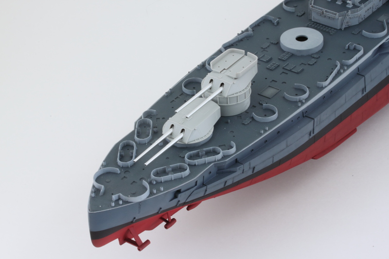
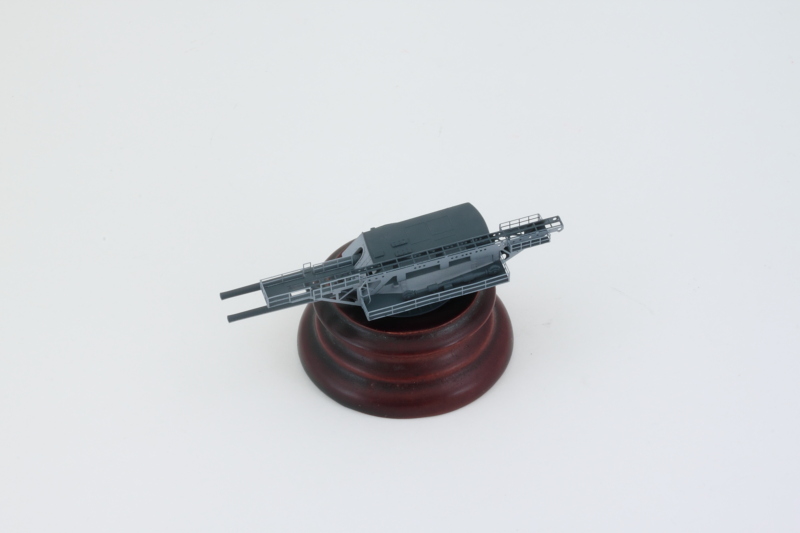
Now the moment of truth, I used the same method as with the other turrets to replace the plastic barrels with the Master aluminum barrels. It's a tight fit but the barrels do clear the catapult properly and everything plays nice together.

Image

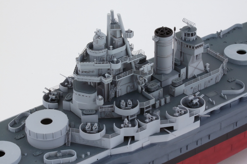
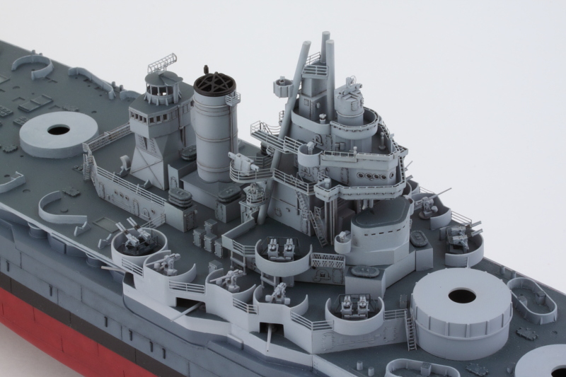
A quick check with the turret in position shows how tight everything fits together in this area along with the tripod mast. Not a lot of room for mistakes!

Image

All of the turret parts, including the catapult, are just dry-fit now so that they can be painted separately to incorporate them into the Measure 22 scheme. It's definitely 'special' when compared to the other 4 turrets.
Bill Plunk
Posts: 1245
Joined: Wed Sep 28, 2022 10:18 pm

WIP 11-06-2015

Post by Bill Plunk »

Every build has its tedious or repetitive elements and today involved one of those kinds of efforts. Since the C turret is now ready for paint, I decided to take advantage of that and also tackle all the different small components like the ammo lockers and ventilators that need Deck Blue. Most of these come from Step 23 while some of the others are from the turret and tripod steps. The downside to all the AA guns on Texas is that they all need their own ammo locker. The small 20mm lockers had 2 connection points on either side that had to be carefully cleaned up and the larger 40mm and 3-inch lockers had 2 points and an ejector mark on their back that had to be dealt with.

While it may not look like much, there's exactly 50 pieces on that strip of masking tape. :)

Image

Another round of airbrush time with the Deck Blue and all of the turret components and those little details got their dose for the Measure 22 scheme. The catapult PE parts and the barrels were primered first with Italian Dark Brown to provide a solid base for the masking needed before the Deck Blue was applied over the primer coat.

Image

Haze Gray round will come next after the appropriate masking so I can get the turret together and start placing some of those small details on the main deck.
Bill Plunk
Posts: 1245
Joined: Wed Sep 28, 2022 10:18 pm

WIP 11-07-2015

Post by Bill Plunk »

Following up from yesterday, today's efforts focused on getting the Haze Gray added to complete the Texas Two-Step scheme. More fun with masking tape required of course with the top of the catapult being the most challenging. For all the little 20mm ammo lockers, I didn't bother with masking and instead used tweezers to hold them and airbrushed at an angle to avoid the previously painted Deck Blue area on top. My poster blue-tack blob provided a convenient place to stick them after painting.

Image

After removing all the masking tape, turret #3 was fully assembled. I assembled the turret halves and guns first so they could be lined up properly and then the catapult components were added next. The trickiest part of the whole deal was adding the side tray that holds the catapult mechanism since the contact surface for it against the turret side is very narrow. I ended up just using some carefully applied amounts of CA to the front and back and with the ladder to get it all lined up properly.

Image

While the turret set up, I added all the little bits to the aft areas of the main deck. There's still more to go in this department, but all the stuff that needed the two-tone treatment got added. Here's where keeping all the turrets, tripod, etc. removable pays off and provides the necessary flexibility to test fit/spacing and still be able to install stuff as needed.

Image

Speaking of which, I added all that stuff back on in dry-fit mode and turret #3 is right at home with no clearance issues. The turret can freely rotate throughout its normal arc with just the right amount of clearance with the tripod and the surrounding stuff.

Image

Just for fun, here's how the stern half of things is shaping up.

Image

Next up will be taking care of the 20mm AA guns that go into the top tubs on #2 and #4 turrets along with a couple other details like the floater net baskets and rafts before I can seal them up for weathering and ultimate installation at some point.
Bill Plunk
Posts: 1245
Joined: Wed Sep 28, 2022 10:18 pm

WIP 11-09-2015

Post by Bill Plunk »

Today was one of those days where I thought I would get a lot further along than I actually did but instead spent the time working on small stuff that was deceptive in the time required to get done. All for the good though as it adds up in being able to check off one more set of the detail stuff required for the rear deck areas.

First up was tackling all the ventilator stuff that is called for in Step 23. These are all molded solid so I used a combination of small drill bits and needle files to open them up and provide a little depth. Admittedly, this isn't something that is going to be all that noticeable but it does make a difference even if it is a subtle one. As you can see, the parts aren't that big to begin with and there are eight of them.

Image

Next I tackled the individual Carly floats/rafts that get attached to the turrets in different spots. There are 6 called for in the instructions, 4 for the #5 turret and 2 for the base of the #4 turret, and that leaves 3 left over on the sprues. I noticed when checking reference photos that there was often a pair also attached to the non-catapult side of the #3 turret so I added 2 more for a total of 8 to the mix. I carefully sanded down their bottom sides so they would sit flat against the turrets as I definitely don't want these puppies coming loose later on. They were hand painted with the help of the Optivisor with a combination of Haze Gray and a custom mix of a medium gray color that I have on hand from a previous effort.

Image

Once the paint was dry, careful use of regular glue to their back sides and placement with tweezers got the job done.

Image

While the rafts were setting up, I added all of the now Haze Gray ventilators to the deck. Hard to believe that the whole day's session was taken up by only 16 parts but there you go. The deck is starting to fill up!

Image

Hopefully I will be able to get to those pesky 20mm AA guns I've been talking about next. :)
Post Reply