Italeri RSO with Pak 40 (2009)
-
Bill Plunk
- Posts: 1245
- Joined: Wed Sep 28, 2022 10:18 pm
Italeri RSO with Pak 40 (2009)
Build log for the 1/35 Italeri kit #355 RSO With Pak 40 along with Aber and Eduard PE, Model Kasten replacement tracks, DML kit #6249 Pak 40 w/ Heer for the Pak 40 parts, and Griffon PE for the DML Pak 40.
-
Bill Plunk
- Posts: 1245
- Joined: Wed Sep 28, 2022 10:18 pm
WIP 08-02-2009
I've been wanting to tackle this kit for a while and finally decided its turn at the bench had come. As you can see from the materials used, this is going to be a kit-bash and PE buffet approach, taking a little bit from here and there to get the desired result that I want. I had at one time contemplated doing the full Aber route and replacing the cab and fighting platform but common sense got the better of me and I settled for a somewhat less ambitious project in the end.
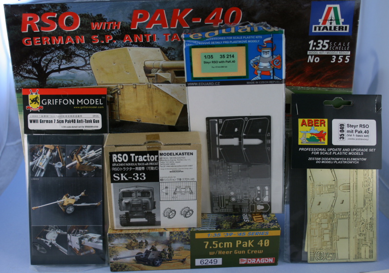
Work began in the Italeri instructions with Step 1 which deals with the construction of the chassis box. This is a multi-part affair with the floor, top, sides, front, and rear parts all separate. The fit was generally good but there was some flash to deal with and of course ejector marks in various places but nothing out of the ordinary for a kit of this age. I did have to use some rubber bands in a couple of places to insure everything lined up square and a combination of liquid glue and regular glue did the trick.
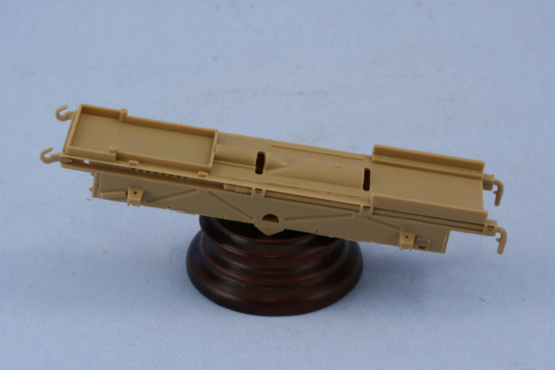
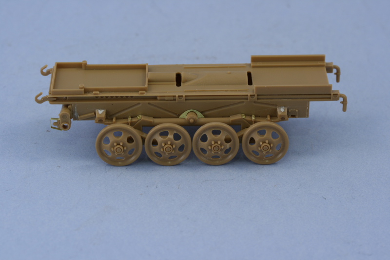
Step 2 began work on the suspension and running gear. I filled the sink marks on the spring mount points with Squadron white putty and sanded smooth. The suspension elements were a tight fit into the hull sides and had to be coaxed a bit to get them all the way up against the sides. The road wheel arms were added next and some Aber PE used to dress up various points that were lacking in detail.
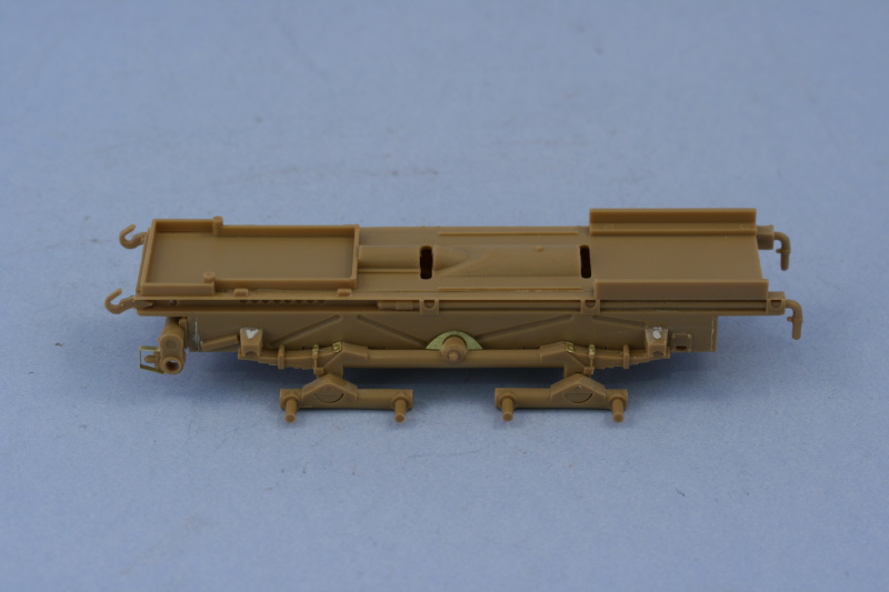
Continuing on with the step, I removed the eight road wheels from the sprues and cleaned up their prominent sprue points and sanded down the large mold seam on each. Some flash had to be removed in the lightening holes as well with a sharp #11 blade. The wheels were then mounted using the cap bolts so that they could fully rotate. They sit a little wobbly but that will be addressed later on after painting when they are glued into their final position and alignment.
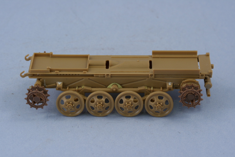
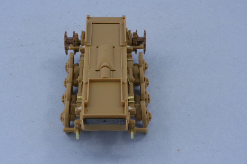
Skipping around a bit in Steps 3 and 4, I went ahead and made the necessary sprocket replacements using the MK parts since the kit-supplied parts have the wrong pitch and won't work with the MK links. The MK parts were mated up with the sprocket backing parts from the kit and test fit front and back.
The MK tracks were assembled, a straightforward process since one of the link pins is already molded on and all that's needed is to add the 2nd pin to assemble the workable links. I assembled two runs of 60 each and then test fit as I added more links with the magic number ending up at 66 for each side despite the instructions calling for 67-68 per side.
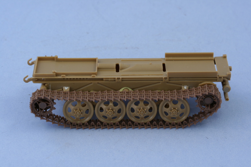
The front set of sprockets were left removable while the rear sprockets are in place due to the mud-scrapers that prevent them from being removable. They aren't glued into position yet so, like the road wheels, are still a little wobbly but that will be taken care of later. Reference photos showed that the mounts for the mud scrapers had hollow circular ends so I drilled out the molded-solid parts with a pin vise to add a little detail before installing them. The left side scraper interfered with the sprocket teeth so I had to sand it down while the right side had no issues at all.
On the front end, I installed the lower hull front cover and added the Eduard key-hole plate between the towing hooks instead of the kit supplied part. The tow hooks were too thick to allow this plate to fit so they were carefully sanded down to correct that and also give them a more in-scale appearance.
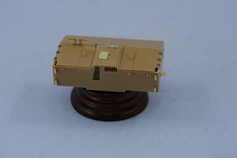
That moved me on to Step 5 which dealt with the assembly of the front cab. Like the chassis box, this is a multi-part assembly with the cab floor, sides, roof, and back as separate pieces. I assembled the cab using liquid glue and once dried used putty to fill some minor gaps and then sanded all the edges smooth to replicate the sheet metal construction as seen in reference photos. I decided I was going to pose the gun in the combat position so that meant closing up the driver's station since this was not manned when the gun was in action. I removed all the molded on detail on the cab exterior sides and replaced it with a combination of Aber and Eduard details. The Aber hinges were designed to be workable but were plain...so this is one case where the Eduard details were superior at least. I also removed the molded on hatches for the engine compartment and replaced them with the Aber hatches. The Aber wing-nuts were a little anemic so I used some left-over styrene parts from a DML Pz IV build in the spares bin instead. The 9 blots that secured the engine compartment cover were added courtesy of the Aber set to round out the front side. Since the right side compartment hatches were molded in one piece with the cab roof, I added the missing panel line at the front with a triangular needle file as well.
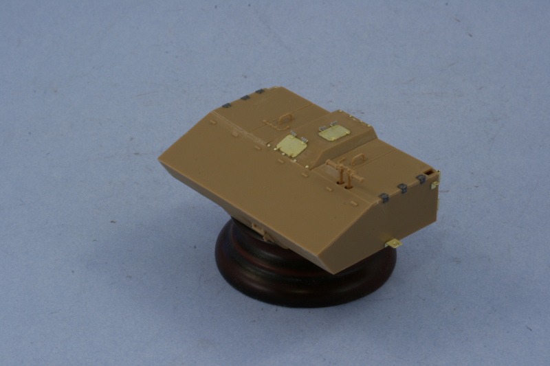
Before constructing the cab, I had removed the molded on detail from the inside that did a poor job of replicating the mesh screens for the engine air intake vents. I used a #70 finger drill to drill a series of holes around the perimeter of each opening and then used the point of a #11 blade to cut through each hole. The opening this created was then carefully cleaned up and the mesh screens added using liquid glue. The screens were extremely delicate but Aber did a great job replicating them IMHO as the reference photos show these were a large mesh type and not the smaller type more commonly seen on tank intakes for example.
Next up will be the work on the Pak 40.
Work began in the Italeri instructions with Step 1 which deals with the construction of the chassis box. This is a multi-part affair with the floor, top, sides, front, and rear parts all separate. The fit was generally good but there was some flash to deal with and of course ejector marks in various places but nothing out of the ordinary for a kit of this age. I did have to use some rubber bands in a couple of places to insure everything lined up square and a combination of liquid glue and regular glue did the trick.
Step 2 began work on the suspension and running gear. I filled the sink marks on the spring mount points with Squadron white putty and sanded smooth. The suspension elements were a tight fit into the hull sides and had to be coaxed a bit to get them all the way up against the sides. The road wheel arms were added next and some Aber PE used to dress up various points that were lacking in detail.
Continuing on with the step, I removed the eight road wheels from the sprues and cleaned up their prominent sprue points and sanded down the large mold seam on each. Some flash had to be removed in the lightening holes as well with a sharp #11 blade. The wheels were then mounted using the cap bolts so that they could fully rotate. They sit a little wobbly but that will be addressed later on after painting when they are glued into their final position and alignment.
Skipping around a bit in Steps 3 and 4, I went ahead and made the necessary sprocket replacements using the MK parts since the kit-supplied parts have the wrong pitch and won't work with the MK links. The MK parts were mated up with the sprocket backing parts from the kit and test fit front and back.
The MK tracks were assembled, a straightforward process since one of the link pins is already molded on and all that's needed is to add the 2nd pin to assemble the workable links. I assembled two runs of 60 each and then test fit as I added more links with the magic number ending up at 66 for each side despite the instructions calling for 67-68 per side.
The front set of sprockets were left removable while the rear sprockets are in place due to the mud-scrapers that prevent them from being removable. They aren't glued into position yet so, like the road wheels, are still a little wobbly but that will be taken care of later. Reference photos showed that the mounts for the mud scrapers had hollow circular ends so I drilled out the molded-solid parts with a pin vise to add a little detail before installing them. The left side scraper interfered with the sprocket teeth so I had to sand it down while the right side had no issues at all.
On the front end, I installed the lower hull front cover and added the Eduard key-hole plate between the towing hooks instead of the kit supplied part. The tow hooks were too thick to allow this plate to fit so they were carefully sanded down to correct that and also give them a more in-scale appearance.
That moved me on to Step 5 which dealt with the assembly of the front cab. Like the chassis box, this is a multi-part assembly with the cab floor, sides, roof, and back as separate pieces. I assembled the cab using liquid glue and once dried used putty to fill some minor gaps and then sanded all the edges smooth to replicate the sheet metal construction as seen in reference photos. I decided I was going to pose the gun in the combat position so that meant closing up the driver's station since this was not manned when the gun was in action. I removed all the molded on detail on the cab exterior sides and replaced it with a combination of Aber and Eduard details. The Aber hinges were designed to be workable but were plain...so this is one case where the Eduard details were superior at least. I also removed the molded on hatches for the engine compartment and replaced them with the Aber hatches. The Aber wing-nuts were a little anemic so I used some left-over styrene parts from a DML Pz IV build in the spares bin instead. The 9 blots that secured the engine compartment cover were added courtesy of the Aber set to round out the front side. Since the right side compartment hatches were molded in one piece with the cab roof, I added the missing panel line at the front with a triangular needle file as well.
Before constructing the cab, I had removed the molded on detail from the inside that did a poor job of replicating the mesh screens for the engine air intake vents. I used a #70 finger drill to drill a series of holes around the perimeter of each opening and then used the point of a #11 blade to cut through each hole. The opening this created was then carefully cleaned up and the mesh screens added using liquid glue. The screens were extremely delicate but Aber did a great job replicating them IMHO as the reference photos show these were a large mesh type and not the smaller type more commonly seen on tank intakes for example.
Next up will be the work on the Pak 40.
-
Bill Plunk
- Posts: 1245
- Joined: Wed Sep 28, 2022 10:18 pm
WIP 08-07-2009
The next step in this build involved assembling the DML Pak 40 to replace the Italeri parts. It involved a lot of small parts so I worked on it in stages in the evenings to allow time for some of the more delicate stuff to set up properly and avoid potential damage.
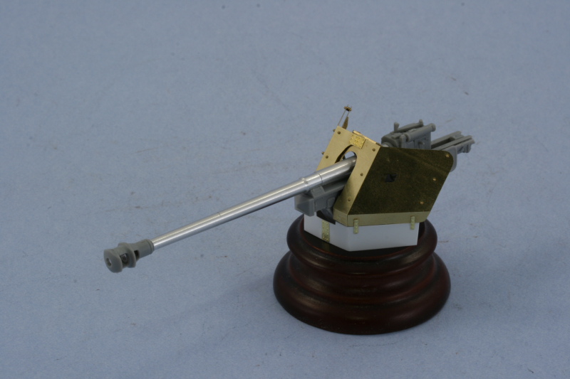
The first order of business was to assemble the 4 piece gun breech. DML's design minimizes the potential for join seams but there were still a couple that needed to be carefully sanded down to get a smooth block. I added the DML-supplied turned aluminum barrel and the fit to the breech has a little bit of play to it so some care was required to get it to sit level. I glued it in place with CA gel and then added the recoil sled. Once that was all set, I assembled the 2-piece muzzle brake and opted for the "final" type of the three offered in the DML kit. The brake only needed a touch of sanding at the front to get a seamless look and then was secured using liquid glue around the joint to allow some work time to get it lined up straight.
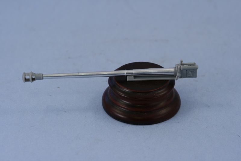
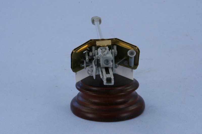
Next up came the gun cradle and all the various gear and equipment necessary for the gun to function. The left side of course was the busiest with the hand wheels and sights for the gunner. I deviated a little bit from the kit instructions in terms of the assembly order after discovering that parts B26 and B27 are backwards in the instructions, the "D" shaped pin that attaches to the equilibrators has to face away from the muzzle, not towards it, as the instructions show. Otherwise this went together smoothly as well. I fitted the telescopic sight for the gunner and drilled out the scope on both ends with a pin vise to add a little more detail. On the right side, I removed the molded on small hatchet mount that wasn't used on the RSO-mounted guns and filled the small mounting holes with putty.
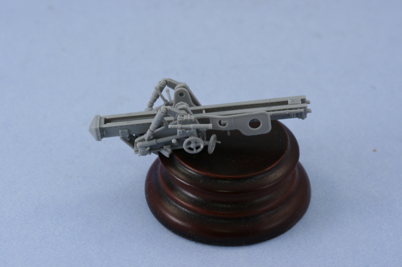
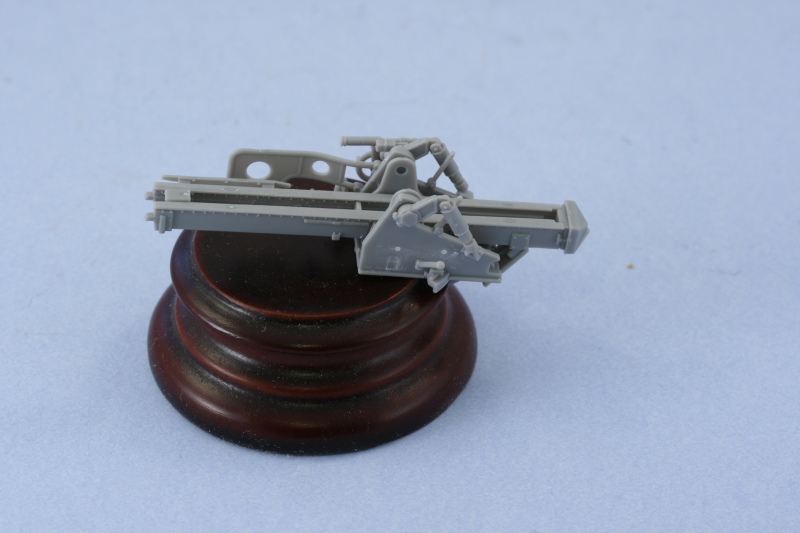
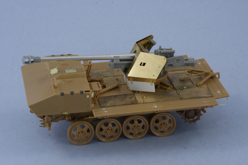
Next was the fun part, constructing the Griffon PE gun shield to replace the kit-supplied styrene parts. The Griffon set is very detailed and assembled smoothly without any major issues, just a lot of parts involved. I started by adding the details on the inside surface of the inner half of the shield. The canisters that mount on the bottoms of both sides as well as the left edge were left off for the time being to avoid damaging them during the rest of the assembly process.
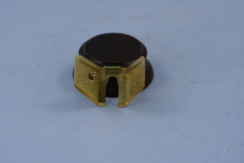
The exterior details were next for the inner half of the shield. The most attractive part of the Griffon set for me was the supplied turned brass bolts with the conical heads, these were added using just a small amount of CA gel on their bases and they fit beautifully into the assigned holes. When I added the shutter plates for the gun sight aperture, even though the instructions call for 2 plates to be laminated together, I found that just using 1 plate was thick enough and glued them into place with a small amount of Gator Grip glue. The same was also true of the sliding plate for the front.
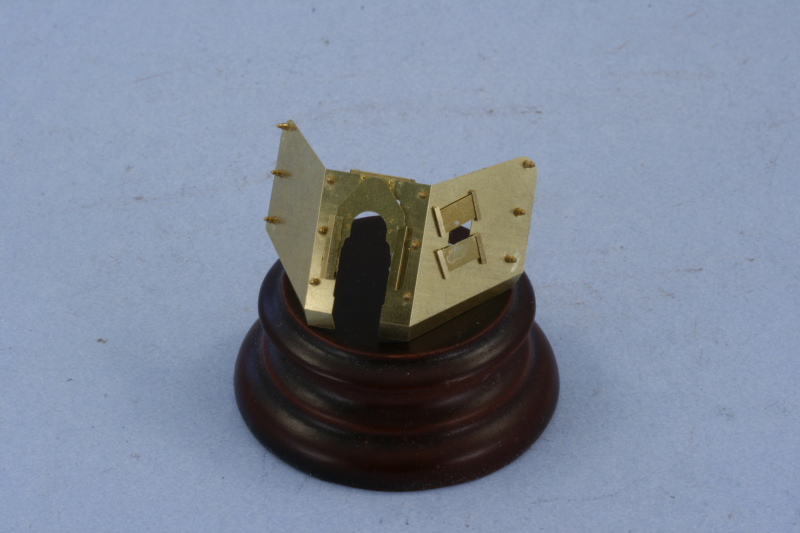
After a test fit and some slight adjustments to the bend angles on the outer plate of the gun shield, it was added using very strategically placed amounts of CA gel to round things out.
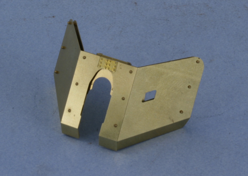
The gun and recoil sled were glued into place on the gun cradle with liquid glue and then the gun shield installed using CA gel and finger pressure. Once secured, I did a test fit of the lower splinter shield plate that was added to in-service vehicles from the Aber set and discovered it was too short. I used some sheet styrene and, with the Aber part has a guide, scratched a new plate and fitted it to the Griffon shield with the Aber bolt strips. The Aber plate was designed to work with the Italeri gun parts and would've been about 3-4mm too short on both sides. Ironically enough, it had the right dimensions in the middle portion!
Next up will begin the work on the gun mount and deck plating.
The first order of business was to assemble the 4 piece gun breech. DML's design minimizes the potential for join seams but there were still a couple that needed to be carefully sanded down to get a smooth block. I added the DML-supplied turned aluminum barrel and the fit to the breech has a little bit of play to it so some care was required to get it to sit level. I glued it in place with CA gel and then added the recoil sled. Once that was all set, I assembled the 2-piece muzzle brake and opted for the "final" type of the three offered in the DML kit. The brake only needed a touch of sanding at the front to get a seamless look and then was secured using liquid glue around the joint to allow some work time to get it lined up straight.
Next up came the gun cradle and all the various gear and equipment necessary for the gun to function. The left side of course was the busiest with the hand wheels and sights for the gunner. I deviated a little bit from the kit instructions in terms of the assembly order after discovering that parts B26 and B27 are backwards in the instructions, the "D" shaped pin that attaches to the equilibrators has to face away from the muzzle, not towards it, as the instructions show. Otherwise this went together smoothly as well. I fitted the telescopic sight for the gunner and drilled out the scope on both ends with a pin vise to add a little more detail. On the right side, I removed the molded on small hatchet mount that wasn't used on the RSO-mounted guns and filled the small mounting holes with putty.
Next was the fun part, constructing the Griffon PE gun shield to replace the kit-supplied styrene parts. The Griffon set is very detailed and assembled smoothly without any major issues, just a lot of parts involved. I started by adding the details on the inside surface of the inner half of the shield. The canisters that mount on the bottoms of both sides as well as the left edge were left off for the time being to avoid damaging them during the rest of the assembly process.
The exterior details were next for the inner half of the shield. The most attractive part of the Griffon set for me was the supplied turned brass bolts with the conical heads, these were added using just a small amount of CA gel on their bases and they fit beautifully into the assigned holes. When I added the shutter plates for the gun sight aperture, even though the instructions call for 2 plates to be laminated together, I found that just using 1 plate was thick enough and glued them into place with a small amount of Gator Grip glue. The same was also true of the sliding plate for the front.
After a test fit and some slight adjustments to the bend angles on the outer plate of the gun shield, it was added using very strategically placed amounts of CA gel to round things out.
The gun and recoil sled were glued into place on the gun cradle with liquid glue and then the gun shield installed using CA gel and finger pressure. Once secured, I did a test fit of the lower splinter shield plate that was added to in-service vehicles from the Aber set and discovered it was too short. I used some sheet styrene and, with the Aber part has a guide, scratched a new plate and fitted it to the Griffon shield with the Aber bolt strips. The Aber plate was designed to work with the Italeri gun parts and would've been about 3-4mm too short on both sides. Ironically enough, it had the right dimensions in the middle portion!
Next up will begin the work on the gun mount and deck plating.
-
Bill Plunk
- Posts: 1245
- Joined: Wed Sep 28, 2022 10:18 pm
WIP 08-09-2009
Made some good progress this weekend, the first order of business was of course to finish up the details on the Pak 40. I added the gear canisters to the lower shields and also added the large vertical canister on the right side. The large canister had its molded on clamps removed with a #11 blade and sanded down to keep its cylindrical shape and the Griffon clamps used in their place.
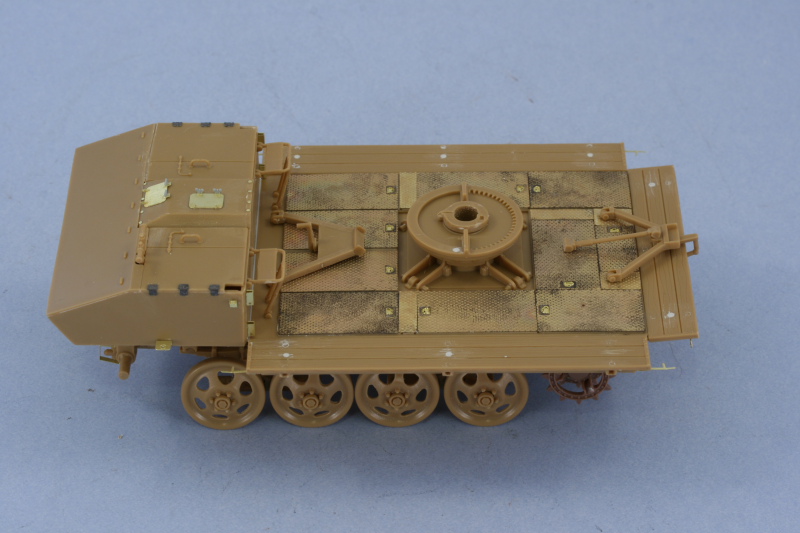
With that taken care of, it was now time to tackle the biggest chunk of the project, the fighting platform deck. The Italeri deck is one-piece and has a raised circular pattern to it that isn't accurate to begin with but also has an incorrect layout in terms of the number of ammo bins and their placement. The Aber detail set provides the means to correct this by essentially "re-flooring" the deck with a series of brass plate sections.
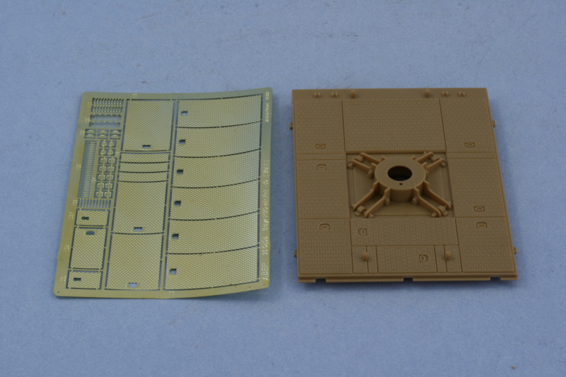
The first order of business of course was to remove the existing raised pattern. I used a crescent micro-chisel for this job and worked one plate at a time. It was a slow and steady process to avoid gouging the deck in the process and once the raised detail was removed, each plate was then sanded smooth and level with a sanding stick.

Because the brass plates were so thin, the tension on the fret had given them a convex shape. This was easily addressed by annealing each plate over a gas flame using my kitchen stove burners and a pair of locking tweezers. Each plate was them carefully flattened and glued into position with CA gel. Aber came up with a neat way to represent the little handle recesses by providing small inserts for each plate that fit flush with the bottom but the parts were tiny so I had to work very carefully with each one since there weren't any spares.

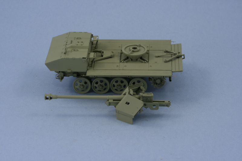
With that out of the way, I mounted the cab and fighting deck to the chassis. There was a slight gap at the join between the two and I filled this with a length of styrene rod and liquid glue instead of trying to use putty in the tight space. Once the rod had softened with the liquid glue, I used a wooden toothpick to gently push and shape it to fill the gap. The two crew jump seats were also added and the travel locks installed in the lowered position. I also added the base plates for the gun mount, adapting the Italeri parts by cutting away the bottom mount plug from the Italeri Pak 40 mount and securing it into place with the kit-supplied locking ring. The DML Pak 40 will mount directly to this when the time comes in order to insure it has the proper elevation and clearance for the gun barrel over the cab.
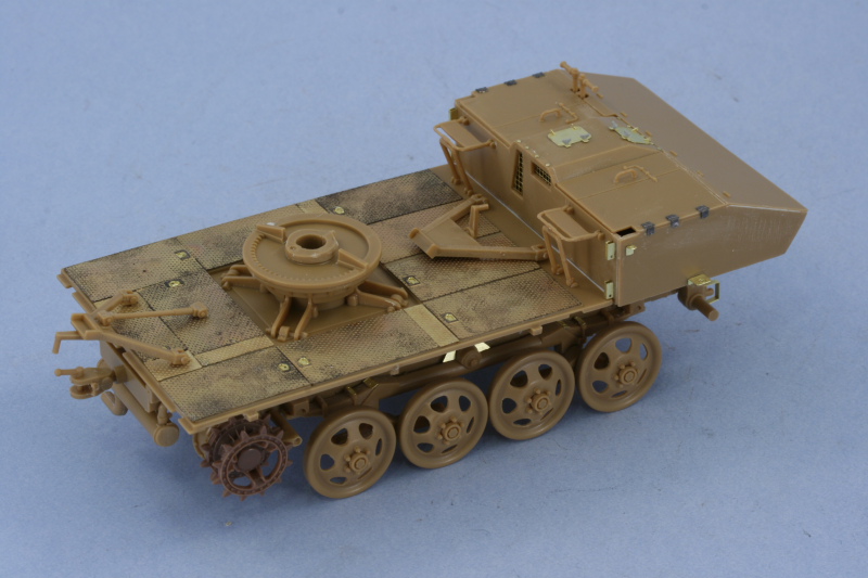
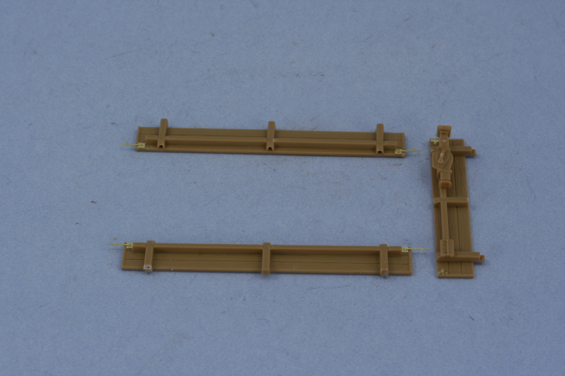
After checking references and seeing mention of this in the Aber detail set instructions, I confirmed that the Italeri wooden sides were too large by one plank. The Italeri parts have 4 planks when only 3 should be present for a production vehicle since 4 were used on the prototype but photos of captured vehicles in PT 7-3 and Allied & Axis #20 clearly show only 3. This meant that the side and rear extensions needed to be re-worked and the top plank removed. This was done using sprue cutters to get a rough cut done and then trimmed down more precisely with a #11 blade and then sanded smooth. With the extensions the right size, this meant that the supports also now had to be adjusted to the right height. I cut off the mount pins with sprue cutters and used them along with liquid glue to plug the holes in the planks and this in turn allowed them to be repositioned to the correct height and the excess length removed from the bottom. The top portions were molded solid but I opened these up for better accuracy by cutting away the solid cap with a #11 blade and then shaping the opening with a square needle file. The latches that were removed along with the top plank were recreated using the Aber-supplied PE parts.
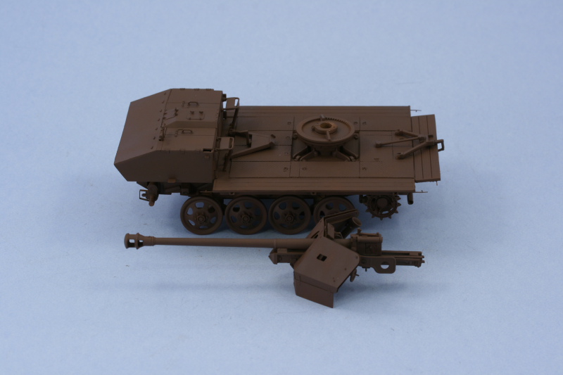
The rear plate required more of a makeover than the sides due to the tight fit it has with the tow pintle, the rear travel lock, and all the stuff attached to it like the jack, Notek light, etc. The mount points for the jack didn't allow sufficient clearance with the tow pintle so these were removed and sanded smooth and the jack moved over about 2mm to the right and glued directly to the brace.
The exposed side of the extensions had some prominent ejector marks that had to be dealt with, these were filled with putty and carefully sanded smooth using a toothpick with some hobby sanding film glued to it with CA gel. The extensions were then installed to the sides and rear in the down position.
Next up will be painting. I've kept the Pak 40 separate deliberately to allow better access to all of its little corners and spaces before it will be installed as the final element.
With that taken care of, it was now time to tackle the biggest chunk of the project, the fighting platform deck. The Italeri deck is one-piece and has a raised circular pattern to it that isn't accurate to begin with but also has an incorrect layout in terms of the number of ammo bins and their placement. The Aber detail set provides the means to correct this by essentially "re-flooring" the deck with a series of brass plate sections.
The first order of business of course was to remove the existing raised pattern. I used a crescent micro-chisel for this job and worked one plate at a time. It was a slow and steady process to avoid gouging the deck in the process and once the raised detail was removed, each plate was then sanded smooth and level with a sanding stick.
Because the brass plates were so thin, the tension on the fret had given them a convex shape. This was easily addressed by annealing each plate over a gas flame using my kitchen stove burners and a pair of locking tweezers. Each plate was them carefully flattened and glued into position with CA gel. Aber came up with a neat way to represent the little handle recesses by providing small inserts for each plate that fit flush with the bottom but the parts were tiny so I had to work very carefully with each one since there weren't any spares.
With that out of the way, I mounted the cab and fighting deck to the chassis. There was a slight gap at the join between the two and I filled this with a length of styrene rod and liquid glue instead of trying to use putty in the tight space. Once the rod had softened with the liquid glue, I used a wooden toothpick to gently push and shape it to fill the gap. The two crew jump seats were also added and the travel locks installed in the lowered position. I also added the base plates for the gun mount, adapting the Italeri parts by cutting away the bottom mount plug from the Italeri Pak 40 mount and securing it into place with the kit-supplied locking ring. The DML Pak 40 will mount directly to this when the time comes in order to insure it has the proper elevation and clearance for the gun barrel over the cab.
After checking references and seeing mention of this in the Aber detail set instructions, I confirmed that the Italeri wooden sides were too large by one plank. The Italeri parts have 4 planks when only 3 should be present for a production vehicle since 4 were used on the prototype but photos of captured vehicles in PT 7-3 and Allied & Axis #20 clearly show only 3. This meant that the side and rear extensions needed to be re-worked and the top plank removed. This was done using sprue cutters to get a rough cut done and then trimmed down more precisely with a #11 blade and then sanded smooth. With the extensions the right size, this meant that the supports also now had to be adjusted to the right height. I cut off the mount pins with sprue cutters and used them along with liquid glue to plug the holes in the planks and this in turn allowed them to be repositioned to the correct height and the excess length removed from the bottom. The top portions were molded solid but I opened these up for better accuracy by cutting away the solid cap with a #11 blade and then shaping the opening with a square needle file. The latches that were removed along with the top plank were recreated using the Aber-supplied PE parts.
The rear plate required more of a makeover than the sides due to the tight fit it has with the tow pintle, the rear travel lock, and all the stuff attached to it like the jack, Notek light, etc. The mount points for the jack didn't allow sufficient clearance with the tow pintle so these were removed and sanded smooth and the jack moved over about 2mm to the right and glued directly to the brace.
The exposed side of the extensions had some prominent ejector marks that had to be dealt with, these were filled with putty and carefully sanded smooth using a toothpick with some hobby sanding film glued to it with CA gel. The extensions were then installed to the sides and rear in the down position.
Next up will be painting. I've kept the Pak 40 separate deliberately to allow better access to all of its little corners and spaces before it will be installed as the final element.
-
Bill Plunk
- Posts: 1245
- Joined: Wed Sep 28, 2022 10:18 pm
WIP 08-16-2009
Work resumed this weekend and the first order of business was to get to the paintwork. The weather cooperated beautifully on Saturday and I spent about 3 hours in the garage with the airbrush. The first step was the application of an overall primer coat of Italian Dark Brown. This allowed me to check all of the sanding and putty work done previously and adjust a few spots where needed. It also insured that I didn't have any bare spots with the plastic, particularly on the undersides, as there's a lot of surface area to this one that makes it deceptive.
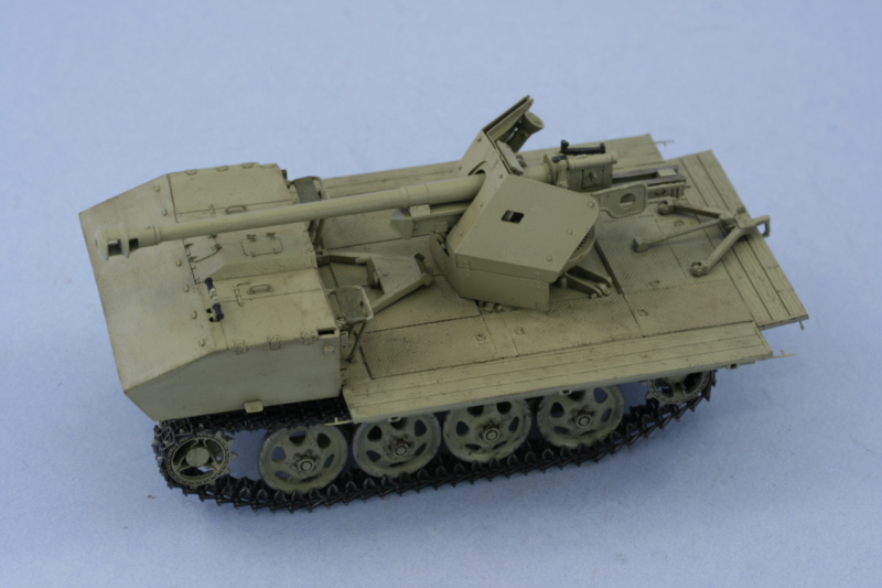
The next step was to apply the base coat of 50/50 Light Gray/Dunkelgelb. I thinned down the paint a little more than usual and used several passes in both a horizontal and vertical pattern to slowly build up the color and avoid losing any detail in the process, especially on the fighting deck platform.
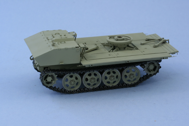
I also used the time in the garage to get the MK tracks painted. The tracks were primered with Flat Black to help protect them from the next coat which is the lacquer-based non-buffing Metalizer Gunmetal, also applied by airbrush. The tracks were then dry brushed with Steel and given an overall wash of thinned enamel Burnt Umber to finalize their look. The road wheels and sprockets had their contact surfaces dry brushed with Steel and then also treated with a wash of Burnt Umber to create the bare metal look I wanted. The loose sprockets were added to the front and the tracks fitted and installed, after which the sprockets were glued into a fixed position with liquid glue to prevent them shifting during later handling.
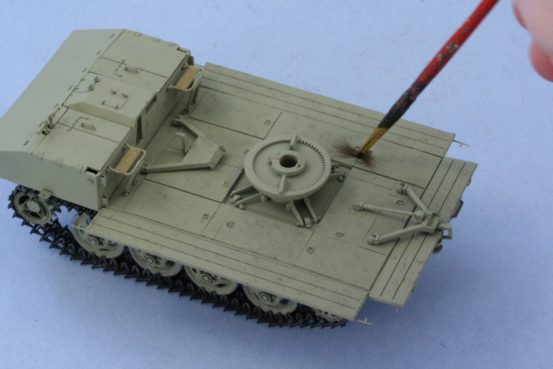
That was allowed to sit overnight and this morning I started in on the details. The fighting deck received some pre-weathering scuffs and scratches using an old 00 round brush and enamel Burnt Umber to create some wear and tear. I used the brush and paint just like I would if I were dry brushing and, with a stabbing motion, applied the wear to different areas in a semi-random fashion. I did the same thing to the road wheels and, with a lighter touch, to the crew compartment hatches on the cab as well.
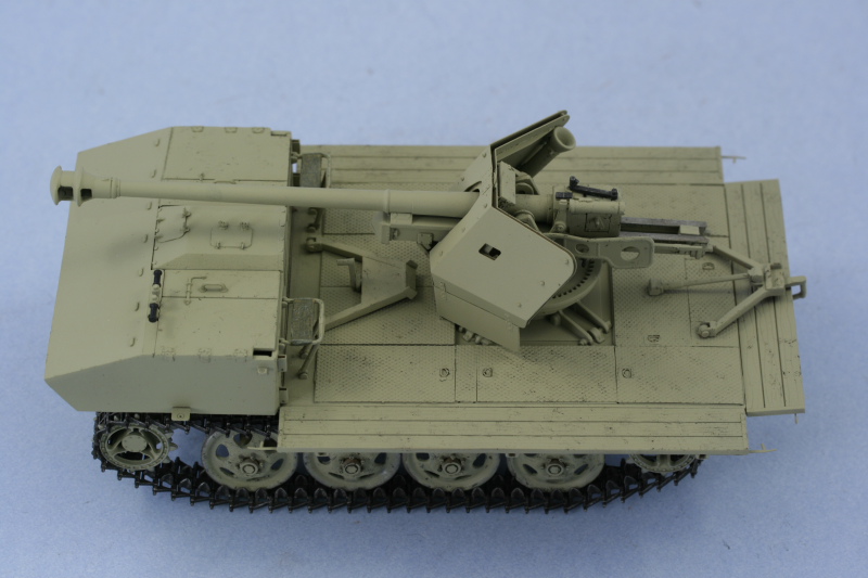
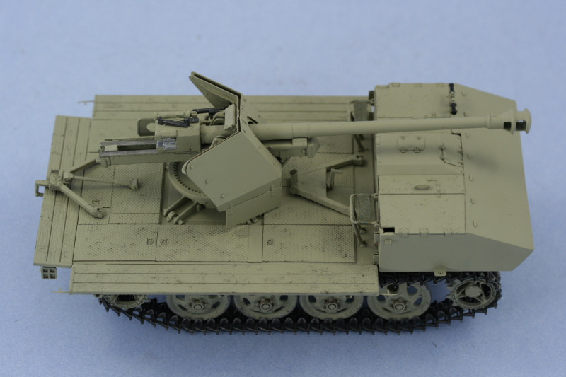
Next up were the gun details on the Pak 40 and the vehicle. The details on the gun were hand painted such as the locking lever for the breech, the gun sight, the breech block, etc. The bare metal surfaces on the recoil sled were painted with Steel and given a light wash of Burnt Umber. I also detailed the canvas jump seats using a layered approach of three colors. The first was Afrika Grunbraun followed by a dry brushed "feld grau" mix of Russian Armor Green/Panzer Gray I keep on hand and then a light dry brushing of the lightened Dunkelgelb mix to round it out and create a cloth-like texture for the canvas. The gun was then glued in position on the turntable base and allowed to dry.
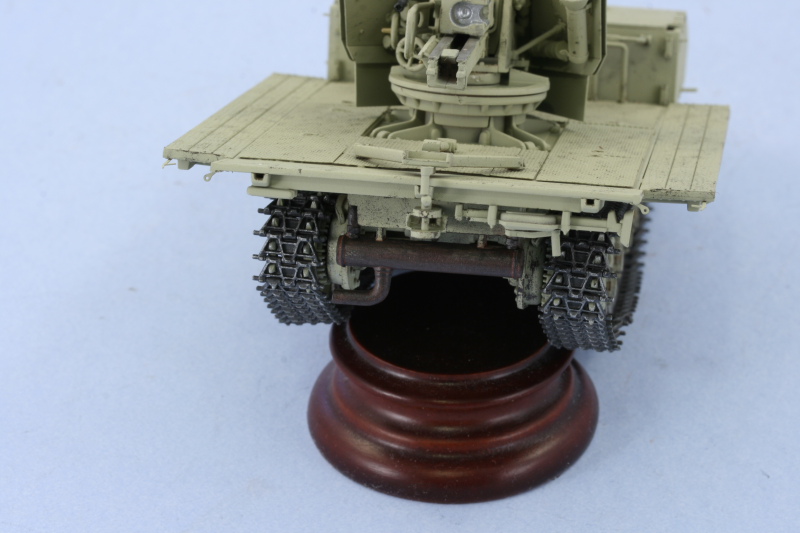
Last but not least, the exhaust was detailed and the underside weathered in anticipation of the later stages. The exhaust was base coated with non-buffing Metalizer Gunmetal and then given 2 successive washes of enamel Rust. Once the washes were dry, I dry brushed enamel Burnt Umber to blend it together and produce some tone variations.
That's all for this weekend...the paint work will be allowed to sit until next weekend to thoroughly cure and set before being sealed and the weathering processes begin.
The next step was to apply the base coat of 50/50 Light Gray/Dunkelgelb. I thinned down the paint a little more than usual and used several passes in both a horizontal and vertical pattern to slowly build up the color and avoid losing any detail in the process, especially on the fighting deck platform.
I also used the time in the garage to get the MK tracks painted. The tracks were primered with Flat Black to help protect them from the next coat which is the lacquer-based non-buffing Metalizer Gunmetal, also applied by airbrush. The tracks were then dry brushed with Steel and given an overall wash of thinned enamel Burnt Umber to finalize their look. The road wheels and sprockets had their contact surfaces dry brushed with Steel and then also treated with a wash of Burnt Umber to create the bare metal look I wanted. The loose sprockets were added to the front and the tracks fitted and installed, after which the sprockets were glued into a fixed position with liquid glue to prevent them shifting during later handling.
That was allowed to sit overnight and this morning I started in on the details. The fighting deck received some pre-weathering scuffs and scratches using an old 00 round brush and enamel Burnt Umber to create some wear and tear. I used the brush and paint just like I would if I were dry brushing and, with a stabbing motion, applied the wear to different areas in a semi-random fashion. I did the same thing to the road wheels and, with a lighter touch, to the crew compartment hatches on the cab as well.
Next up were the gun details on the Pak 40 and the vehicle. The details on the gun were hand painted such as the locking lever for the breech, the gun sight, the breech block, etc. The bare metal surfaces on the recoil sled were painted with Steel and given a light wash of Burnt Umber. I also detailed the canvas jump seats using a layered approach of three colors. The first was Afrika Grunbraun followed by a dry brushed "feld grau" mix of Russian Armor Green/Panzer Gray I keep on hand and then a light dry brushing of the lightened Dunkelgelb mix to round it out and create a cloth-like texture for the canvas. The gun was then glued in position on the turntable base and allowed to dry.
Last but not least, the exhaust was detailed and the underside weathered in anticipation of the later stages. The exhaust was base coated with non-buffing Metalizer Gunmetal and then given 2 successive washes of enamel Rust. Once the washes were dry, I dry brushed enamel Burnt Umber to blend it together and produce some tone variations.
That's all for this weekend...the paint work will be allowed to sit until next weekend to thoroughly cure and set before being sealed and the weathering processes begin.
-
Bill Plunk
- Posts: 1245
- Joined: Wed Sep 28, 2022 10:18 pm
Completion 08-23-2009
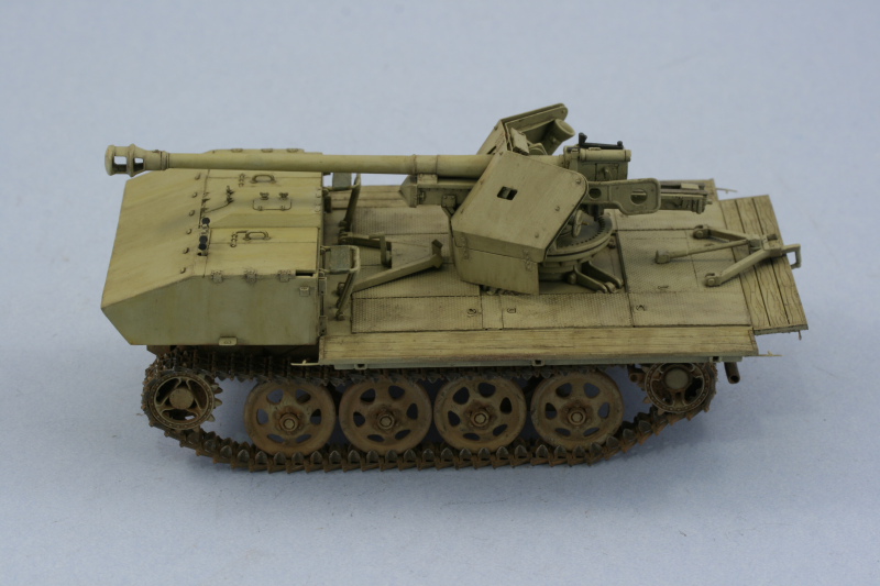
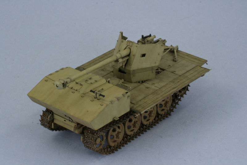
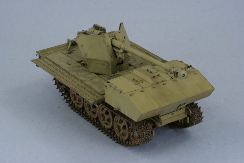
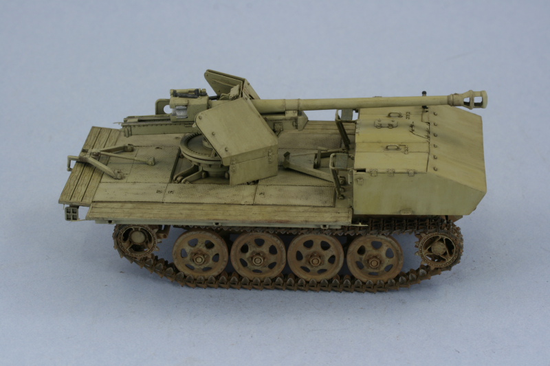
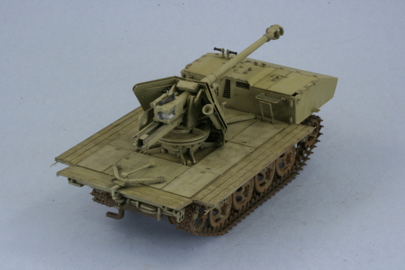
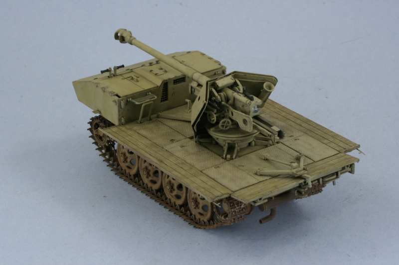
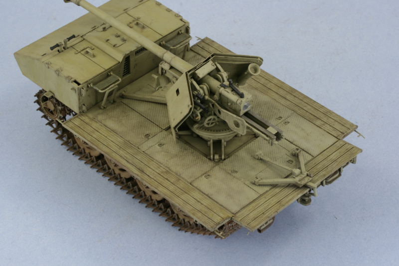
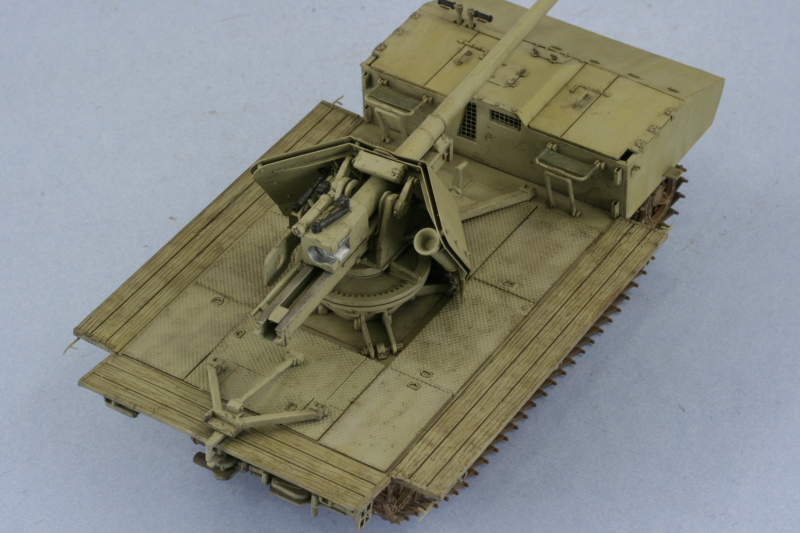
Efforts this weekend went towards the weathering and final hurdles to get this one completed an in the books as #98. The first step was to seal the entire vehicle with an airbrushed coat of Future. I paid particular attention to the deck of the fighting platform to insure it was thoroughly sealed due to the texture and surface of the Aber plates. The Future was allowed to dry thoroughly for 2 days, not because that amount of time was necessarily needed but because that's just how it worked out!
The weathering foundation was laid with the application of an overall wash of enamel Raw Umber applied with a round sable brush.
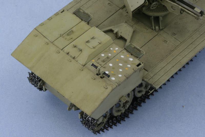
Once that had dried, the next step was the application of dot filters to provide variation and weathering to the monotone base coat. Since this was a plain dunkelgelb finish, I chose colors that would supplement that in the form of Flat White, Deep Yellow, and original Panzer Dunkelgelb. These dots were blended together using a #2 square tip blender brush dampened with thinner. The dots were combined in with the underlying wash coat of Raw Umber working in small sections at a time while wearing a breather mask to avoid over-exposure to the thinner fumes.
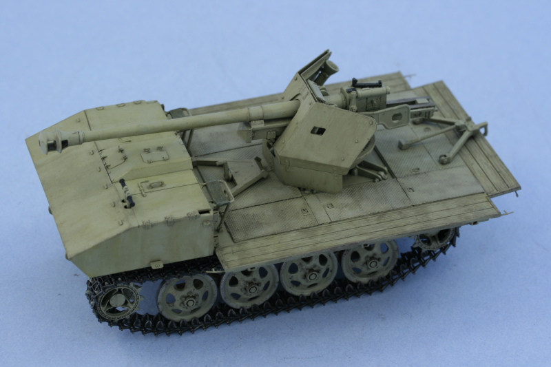
The next step was the application of a pin wash of enamel Burnt Umber to all the raised details and various panel and join lines. Excess wash was carefully cleaned up with a pointed 10/0 brush and clean thinner and then the entire vehicle received a coat of Testors Model Master Lusterless Flat via spray can. Once the flat coat was dry, I applied a mix of Mig Pigments Dark Mud, Dry Mud, and Europe Dust wet to the tracks, running gear, and lower hull and let it air dry. Excess pigment was removed using stiff-bristled brushes while wearing a dust mask and additional pigment removed with a combination of wet and dry q-tip ends until I had the look I wanted.
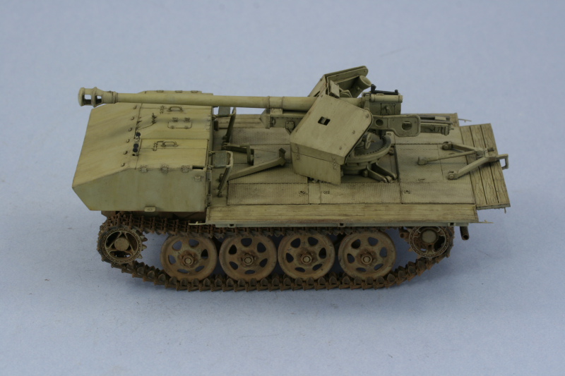
The final step involved lightly dry-brushing some Steel to the contact surfaces on the guide horns and track faces and then it was off to the photo both for the walkarounds.
The weathering foundation was laid with the application of an overall wash of enamel Raw Umber applied with a round sable brush.
Once that had dried, the next step was the application of dot filters to provide variation and weathering to the monotone base coat. Since this was a plain dunkelgelb finish, I chose colors that would supplement that in the form of Flat White, Deep Yellow, and original Panzer Dunkelgelb. These dots were blended together using a #2 square tip blender brush dampened with thinner. The dots were combined in with the underlying wash coat of Raw Umber working in small sections at a time while wearing a breather mask to avoid over-exposure to the thinner fumes.
The next step was the application of a pin wash of enamel Burnt Umber to all the raised details and various panel and join lines. Excess wash was carefully cleaned up with a pointed 10/0 brush and clean thinner and then the entire vehicle received a coat of Testors Model Master Lusterless Flat via spray can. Once the flat coat was dry, I applied a mix of Mig Pigments Dark Mud, Dry Mud, and Europe Dust wet to the tracks, running gear, and lower hull and let it air dry. Excess pigment was removed using stiff-bristled brushes while wearing a dust mask and additional pigment removed with a combination of wet and dry q-tip ends until I had the look I wanted.
The final step involved lightly dry-brushing some Steel to the contact surfaces on the guide horns and track faces and then it was off to the photo both for the walkarounds.
-
Bill Plunk
- Posts: 1245
- Joined: Wed Sep 28, 2022 10:18 pm