Tristar Pzkpfw 38(t) Ausf. B with Interior Cutaway (2009)

Bill Plunk
Posts: 1245
Joined: Wed Sep 28, 2022 10:18 pm

Tristar Pzkpfw 38(t) Ausf. B with Interior Cutaway (2009)

Post by Bill Plunk »

This build is a little special as it marks my 100th armor model build. I started back in the hobby in 2002 so it's taken just 7 years to get to this point.

This build features the Tristar kit #35026 Pzkpfw 38(t) Ausf B plus the Tristar Pzkpfw 38(t) Interior set #35032 as well as a Griffon turned aluminum main gun barrel and Lion Marc brass Vz37 machineguns. I'll also be using a set of ModelKasten SK-30 workable tracks.

Image
Bill Plunk
Posts: 1245
Joined: Wed Sep 28, 2022 10:18 pm

WIP 09-13-2009

Post by Bill Plunk »

Since I'm building this kit up with a full interior, the build order will skip around a bit from that outlined in the standard vehicle instructions. I started in with the interior set and the first order of business was the construction of the brakes. This is a multi-part affair with PE strips provided to create added detail for the brake straps. The steering levers were added next along with the transmission and the drive shaft.

Image

The hull floor required a little bit of clean up in the form of filling or sanding down various ejector marks. This was easily taken care of using a sanding twig and some Squadron White putty. The driver and radio operator seats and their mounts were assembled next and then installed. It took a couple of attempts to get the driver's seat positioned properly, I had to do multiple test fits with the hull side and the transmission before I found the sweet spot as the space is very tight with hardly any tolerance to either side. There aren't any locator marks to aid in their positioning so once I had the driver's seat lined up properly, I used it as a guide to then add the radio operator's. The transmission and brake housing are dry fit only at this stage to give an idea of how it will all work together.

Image

Going by the various reference pics of the interior of 38ts from Panzer Tracts 13 and Spielberger, I masked off the appropriate areas on the floor and the hull sides and painted the red oxide areas of the interior and engine compartment. I mixed up my own flavor using Testors Flat Red, Flat Black, and a little bit of Light Gray and sprayed via air brush. I had installed the engine compartment fuel tanks but left the radiator and water tank separate as their exact position is dependent on the engine and I needed to construct and install that first.

Image

Speaking of the engine, that's what I worked on next. The Tristar parts provide a lot of detail and I had to think strategically about the assembly and paint sequences in order to be able to get to everything. I ended up assembling the block and painting it first, then painting and adding the various additional details individually as I went along. Once the whole engine was assembled, I gave the whole thing a light wash of thinned Aircraft Interior Black since it's got a bit of a satiny sheen to it, perfect for simulating oily grime IMHO.

Image

Image

I also detailed the battery rack on the left side as well as the fuel caps on the tanks. I added some of the same wash here to simulate fuel stains/spills and generally get it to match the engine. Don't mind the small marks on the hull side of the tanks, that will be hidden away from view once the hull sides are added to the floor. The engine is only dry fit for now, I still need to do some work with the radiator and the firewall before it will be permanently installed. Depending on the space restrictions, I may add some fuel lines between the tanks and the engine if I can make it work...if not, I'll leave things as is for this part of the interior.

Image
Bill Plunk
Posts: 1245
Joined: Wed Sep 28, 2022 10:18 pm

WIP 09-19-2009

Post by Bill Plunk »

Today was a very productive day and at every step along the way I have to keep reminding myself it's all about the details! This in turn means that I have to give a lot of thought to the how and when things are dealt with...and that means things often happen in bursts.

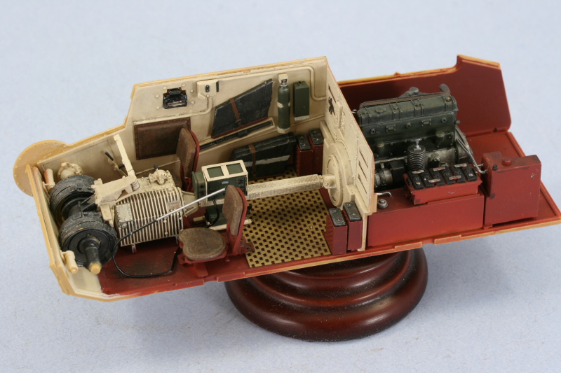
The first burst was to add some detail to the engine area. I installed the engine permanently into position using the firewall as a prop to insure the engine sat level while the glue dried. After it had set, I used a #72 finger drill and drilled some shallow holes in the fuel tanks to support some fuel lines. The diagrams in PT 13 show that the fuel lines fed to the pump panel on the firewall so I used some 1mm diameter solder for the lines and glued the ends into the drilled holes with CA gel and then carefully bent them into the desired shape. The will be glued into the panel on the firewall once it's installed to insure everything connects up. The diagram also showed two lines running from the auxiliary reserve fuel tank on the left side towards the engine so those were added as well. The engine still needs the exhaust pipe running out to the exterior, I will add that once the radiator is installed.

Image

Next up was the hull glacis plate. I had decided not to open up the hatch here to display the brake housing due to the way the hatch opens up, so it was installed closed. I added the clutch pedal and instrument panel and other small details. Test fits showed that I needed to sand/trim down a bit in the center for proper clearance on the steering lever column. Not sure if this is a kit issue or one I introduced in assembling the column, but either way it had to be dealt with to avoid problems with the hull sides fitting correctly.

Image

Continuing on with the hull front, the superstructure front plate received various details in the form of the radio opertor's visor and armored glass block, the driver's periscope and housing, and the communication light panel with the commander. Due to the curved plate, there was a large ejector mark dead center that required some very careful putty and sanding work to deal with. The curve also meant that the position of the light box ended up slightly different that what is displayed in the Tristar Interior Set instructions. Those instructions assume the front plate is straight as seen on the E/F and G variants so I had to improvise a bit to get it in the right spot and still clear the hull side panel. The improvisation involved trimming down the molded-on wire conduit there by a couple of mm to accommodate the bent plate design. I used poster blue-tack putty to mask off the portions of the clear parts that I needed to preserve clear and that was it for this part.

Image

Speaking of the hull sides, it was now time to give them some attention as well. I installed the axle hubs into the brake housing and used strips of masking tape to hold the hull sides upright with the floor to insure they fit properly and lined up straight. The driver's side received the parking brake lever as well as the electric fuel pump switch. The case for the signal staff was added and the periscope for the side view port added with blue tack masking.

Image

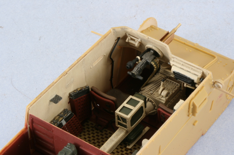
Continuing on with the fighting compartment interior, I assembled the various ammunition racks for the main gun as well as the 2 MGs. The Interior Set provides some excellent PE holders that were bent to shape with pliers and tweezers. Only the MG holders proved a tight fit, the ammo cans have small raised ridges that had to be trimmed off to allow them to slide in and out without bulging the cases in the process.

Image

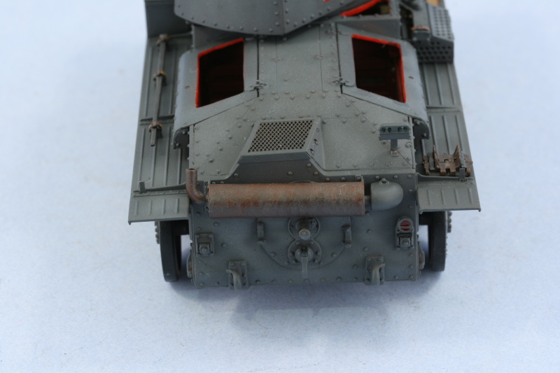
The fighting compartment roof was also cleaned up with some ejector marks needing attention. I've decided that I'm going to cut away the portion of the roof over the driver's side while leaving the turret ring area intact to support the turret. Before doing that, I will paint the underside to insure consistency in what remains. I'm going to do something similar with the engine deck hatches, so those too were prepped with their ejector marks filled and sanded and the kit-supplied PE grills installed. Last but not least, the rear hull panel had the circular cover added and the external details that mount through the hull added so that they could be painted over prior to installation.

Image

That brought me to the turret. The first order of business was the roof and the commander's cupola. I assembled the cupola per the kit instructions but left off the view port periscopes for now since I can easily install them from the underside after the roof has been painted with the interior color.

Image

The main gun assembly came next. The kit-supplied barrel is too long when compared to the plans in PT 13 so I replaced it with the Griffon turned aluminum barrel. The kit barrel was removed at the base and the Griffon barrel glued into position at the correct length inside the mantlet with CA gel. The recoil cylinder and gun base where then added along with the breech and block. The recoil guards and spent shell bag were installed next.

Image

The gun was then installed to the turret front plate, following the instructions carefully to insure it could still elevate freely. I encountered a problem when trying to install the gunner's sight...it seems the Tristar instruction writers didn't realize that the design of part B26, the scope, makes it impossible to fit the locking square plate, part B27, over it as called for. The only way to install it is to remove the mount tab that's molded onto the side of the scope and is supposed to attach to the main gun so that they move coaxial, slide the plate into position, then re-glue the mount tab back onto the scope. I also drilled out the eyepiece on the scope with a pin vise and added the elevation gear and shoulder traverse to the gun to round things out. The coaxial MG will get added later on, the internal locking ring will be painted first and then installed along with the MG when the time comes.

Image

The rest of the turret also needed some additional attention. Since there isn't any detail on the turret sides (just as on the real vehicle), I will cut away portions on both sides of the turret so you can see through from both sides as well as down into the fighting compartment. Just as with the roof, I went ahead and cleaned up their ejector marks and sanded them down in preparation for painting since I don't know exactly which areas I'm going to cut away just yet. The turret roof will remain intact since the space next to the cupola mounts an ammo bin for the main gun and I wanted to preserve that...the ammo bin is only dry-fit in this pic to give an idea of where it will sit. I also constructed the rear turret ammo bins from the Interior Set PE. These had to be modified slightly in order to fit properly by removing the rear fold-up ends on the bins. These aren't deep enough for the cans to sit correctly and were snipped off with sprue cutters to allow for proper clearance. The tool drawer chest that sits between the two ammo racks was glued into position and the commander's turret traverse and light box was added to the turret side. Getting that in the proper position is crucial as it needs to line up with the rivets on the exterior as well as clear the turret ring on the bottom so some careful fitting was called for before gluing it into position.

Image

With all that detail work done, it was now time to paint. I applied Testors Model Master Panzer Interior Buff enamel by airbrush and used my custom mix of Red Oxide primer for the various parts I'd missed the last time around.

Image

Now it's time to start adding these parts together and working on even more of the details!
Bill Plunk
Posts: 1245
Joined: Wed Sep 28, 2022 10:18 pm

WIP 09-20-2009

Post by Bill Plunk »

Building on yesterday's foundational paint work, today was all about painting and installing the various details. I spent virtually the whole day painting and detailing items and it was only as I got to the end of the session that things finally started to get installed.

The first set of details to get installed were on the driver's side. I added the crash pad, the signal staff, main gun ammo can, and fire extinguisher after hand painting them prior to installation. The Interior Set neglected to provide a first aid kit that is supposed to be next to the FE, so I scrounged around in my spare PE fret bin until I found a box shape of suitable size/dimensions to use. I used the old artist trick of "trompe leoil" by painting in the "rack" that it's supposed to be sitting in on the base so it looks like it has a holder. I applied a wash of Raw Umber to weather the elfenbein and then dry brushed some of the enamel Panzer Interior Buff over that to blend it back in and give it a slightly grungy look.

Image

The radio operator's side got a similar treatment and the two ammunition holders were installed. Getting them into the right position required a careful check of my interior reference photos in PT-13 since the Tristar Interior Set instructions are vague at best as to their exact placement. Since they have to clear the MG ammo bins attached to the firewall and the radio operator's seat, the tolerances are very tight with no room for error. To insure I got them in the right position, I used the masking tape trick again to hold the hull side to the floor with the firewall dry fit in position and then carefully glued the racks in place with CA gel. The white stripe on some of the ammo cans is something that shows up in the PT 13 interior photos, my guess is that it distinguishes between HE and AP rounds but I can't be sure. I added the stripe using masking tape and careful application of Light Gray by brush.

Image

Next up was the transmission/brake housing/drive shaft. Even though the brake housing won't be seen, I still painted it up just to be sure that there wouldn't be any bare plastic viewable. The transmission was given a wash of Raw Umber and then dry brushed just like the hull sides. The Interior Set provides two different radio sets but since this is a normal vehicle and not a command tank, I only used part H48 for the receiver that a standard tank would be equipped with. PT 13 indicates in the text that the receiver was mounted to the drive shaft so it was positioned that way deliberately. The Tristar Interior Set instructions don't provide any advice/help at all on where the radio is supposed to go since it's a generic set meant for any of Tristar's 38(t) vehicles including the command variants. I also wired it up with some 1mm diameter solder that will connect up to the antenna pot on the hull front plate once that's installed.

Image

I also painted and installed the seat cushions for both crew positions. The driver's cushions had to be adjusted slightly to clear both the hull side and the transmission while the radio operator's went on just fine with no issues. The MG bins were added to the firewall and then the flooring for the area below the turret added to get it aligned properly. The transformer for the radio receiver was added, the rack for which I cut down since it was designed to hold transformers for both a transmitter and receiver. It too was wired up so that it could be connected to the receiver once it was installed. The double ammo bins for the driver's side were detailed and installed with the outer can receiving a white stripe as well. I also weathered the exposed floor areas with dry brushed Steel and Burnt Umber but I don't think very much of it will be visible in the end...but at least I know it's there!

Image

The superstructure front plate also received some attention. It received the same wash and dry brush treatment as the rest of the interior and the driver's periscope was detailed with Flat Black and the green-red-blue signal lights added using regular Testors enamel Beret Green, Flat Red, and Sea Blue. The MG will get added later once the plate is installed to avoid the possibility of damaging it.

Image

With all that taken care of, Franklin needed to start getting assembly...so the driver's side was added first to the floor using regular glue and finger pressure to get a good join.

Image

Same thing was repeated for the radio operator's side.

Image

The final act for the day was to add the glacis plate and the rear hull plate to insure that the hull sides were lining up properly. The glacis plate required the use of some rubber bands to get it to sit down flush at the front due to the fact that it needed to align in three different directions to sit at the right angle. After about 15 minutes the bands came off and the hull was together.

Image

I played around with the lighting a bit and wanted to show off some more of the detail, especially the straps on the ammo cans. Those required some careful work under the magnifier and are tough to see in the previous shots. Keep in mind that there are 15 cans in all including the ones in the turret. I also neglected to mention that I had added the small foot step for the commander using a leftover part from an Eduard PE fret. Getting that in the right position was a challenge as it had to have sufficent clearance that the ammo cans could be removed but still be low enough on the hull for the commander to actually put his foot on.

Image

Image

Just as a trial run, I also dry fit the superstructure front plate, the hull roof with the turret bottom in place, and the rear engine deck to see how much would be visible without any modifications being done. Since the 38(t) doesn't have a turret basket or any other means to support the turret aside from resting inside the ring, I'm going to retain that portion of the roof but cut out everything else, leaving only the perimeter of the rivet lines plus the turret ring support. I think this will, when combined with cutting out the turret sides, provide quite a bit of visibility down into the interior while still allowing the vehicle to be displayed intact vs. having the turret separate for example.

Image

Next up will be working on the turret details and then it will be time to do some cutting and fitting of the remaining external details.
Bill Plunk
Posts: 1245
Joined: Wed Sep 28, 2022 10:18 pm

WIP 09-24-2009

Post by Bill Plunk »

A little bit of a mid-week update. Work has been slowly continuing on the details in the turret a little bit at a time and I finally got enough progress together to justify the pics.

Due to the narrow confines of the two-man turret, the turret sides themselves are devoid of detail except for the commander's traverse gear and the light communication system with the driver. This was added courtesy of the Interior Set and detailed based on the reference photos in PT13. The 38t turret doesn't have any kind of exhaust or ventilation system and the vent gasses from firing the main gun were expected to escape out the commander's hatch, the vents into the engine compartment, or out the lower hull air port next to the radio operator. Bearing this in mind, I allowed for a little more grime accumulation inside the turret than I had in the lower hull but used the same formula of a Raw Umber wash followed by repeated dry brushing of the Panzer Interior Buff to vary and blend it back into the base coat. I also detailed and installed the commander's periscopes and bump pads into the cupola. As a small touch I also made sure to paint the underside of the small signal hatch Panzer Gray to match the exterior even though it's molded closed...it's the principle of the thing! Much of the turret sides are going to be drilled out and removed but what remains should look consistent with the rest of the interior from a weathering perspective.

Image

Image

The main gun and turret front plate also received their share of detail attention. The kit parts for this provide a lot of detail all on their own and I dutifully detailed the gunner's scope, the spent shell basket, and the leather padded manual shoulder traverse (I can only imagine what pushing THAT would feel like!). The same wash/dry brush treatment was applied as well. I still have yet to install the coaxial MG, that will come in later steps once I get the turret built but before I add the roof.

Image

That about rounds things out for now in the detail department, now I need to focus on getting into the exterior construction and start pulling this baby together!
Bill Plunk
Posts: 1245
Joined: Wed Sep 28, 2022 10:18 pm

WIP 09-27-2009

Post by Bill Plunk »

This weekend was yet another highly productive effort so apologies in advance for the high number of pics in this update! Last time I said I was done with the details but that wasn't quite true...I still needed to install the turret ammo bins in the rear and on the roof. The fit tolerances here are very tight so I used several small strips of masking tape to hold the turret sides and rear together so I could get the placement correct. There is supposed to be a small tool case that goes between the tray box in the middle and the ammo bin on the right but there isn't enough space in the whole turret rear to make this work. Add to this the fact that the tool case in the Interior set is molded too tall and it got left off. A shame because it was a nice detail to have. The ammo bins were glued in place with CA gel to round out things here.

Image

Now came the moment of truth...the creation of the cut-away sections. I gave this a lot of careful thought and opted to go with a method I've used before for smaller similar sections. The method is simple...perforate the sections needing to be removed using a micro drill bit and then cut through the perforations with a razor saw to remove the large chunks. Then the edges need to be smoothed out with a #11 blade and then sanded down where necessary to get a smooth edge. This method was applied to the turret sides, the hull roof, and the engine compartment covers. This effort took almost the full day yesterday to get it done but was worth it.

Image

Image

Image

With that out of the way, it was time to finalize the assembly of the interior on both the lower hull and turret. First up was the installation of the superstructure front plate. I added the hull MG, replacing the kit exterior barrel and tray with the ones from Lion Marc. The Lion Marc set includes pre-formed brass trays and gun sights but the gun sight is very fragile/tiny, so I left that off until later to avoid the possibility of losing it. I drilled out the eyepiece for the sight with a pin vise and added an ammo belt courtesy of a left over item from a DML kit in the spares bin. The ammo belt was trimmed for length and bent to shape to fit the confines of the compartment before getting detailed and installed.

Image

I also completed the wiring for the radio antenna. The length of solder I'd installed earlier was trimmed down to the desired length and a couple of small retaining brackets added using the flexible PE attachments from an old Eduard PE set cut to size and bent to shape with a piece of solder and tweezers. The brackets were then glued in place with small dots of CA gel to hold the cable in place.

Image

The rear engine deck was added next, using careful applications of liquid glue and finger pressure to get a solid join all around. I did have to trim down slightly one of the ridges on the radiator that mates up with the air intake vent for everything to sit properly. The hull roof was then added in the same fashion and then set off to the side to allow the glue to dry.

Image

The turret coaxial MG was added to go with the main gun, receiving the same type of detailing as with the hull MG. The only difference here is I opted for a shorter belt due to space constraints and to avoid the belt hanging down into the hull and potentially snagging on items there.

Image

The Lion Marc barrel and tray were added to the exterior and the assembly work begun on the turret. I added the sides first followed by the rear plate and finally the front plate. The Tristar instructions indicate that you should have the turret roof in place before adding the front plate but this is virtually impossible to do because of the dimensions on the spent shell basket and the narrow confines of the turret itself. I learned that lesson when I built the Tristar E/F so was already aware of the pitfall.

Image

The turret roof was added and carefully mated up with all the different surfaces using liquid glue, patience, and finger pressure. Some small amounts of putty were needed on the turret underside where the side panels meet up with the bottom but otherwise the overall fit was good. I also added the commander's periscope and the rain guard over the gunner's sight.

Image

A test fit with the hull showed everything lining up perfectly.

Image

Now I could finally go back to the "normal" order of construction on the exterior and the first order of business was the suspension. These were assembled according to the directions in Step 1 and added to the lower hull. I left the swing arms and springs fully workable until I added the wheels to be sure I could achieve a level fit. The sprocket housings were also installed along with the return roller mounts although I left off the rubber portions of the rollers for the time being to make it easier to paint and detail separately.

Image

I also removed all the road wheels and cleaned up the mold seams on the separate tires with a sanding stick. The sprockets were assembled along with the idlers with the idlers getting the added bonus of their mount arms installed so they can remain movable when it comes time to add the tracks.

Image

And last, but not least, the road wheels were installed to the suspension arms and the arms then glued to the spring bundles to insure the suspension sat level. The sprockets and idlers were dry fit to insure everything lined up ok. I also filled in the mounts for the front wheel bump stops with putty and sanded it smooth as these weren't present on the Ausf B. Tristar incorrectly carried this over from the later Ausf 38ts that they've also molded but they weren't fitted until the Ausf C. A small accuracy issue but one easily dealt with. I also puttied in the small mount holes for the shovel and pick-axe since the vehicle I'm depicting will have the stowage box mounted on that fender instead. This is an option that Tristar provides in the kit but they never tell you to fill the mount holes if opting for that particular configuration.

Image

Next up will be the fenders and the remaining exterior details and then it will be on to paint!
Bill Plunk
Posts: 1245
Joined: Wed Sep 28, 2022 10:18 pm

WIP 10-03-2009

Post by Bill Plunk »

I managed to get all of the construction work done on this project today but due to rain wasn't able to start painting. Hopefully the weather will improve tomorrow, we'll see!

In the course of the past week I started the assembly of the MK replacement workable tracks. I find that it's best to work on these a little bit at a time while watching TV, it helps break up the monotony/repetition involved in their assembly. The MKs for the 38t assemble very straightforward, pins on either side using the supplied jig and you can assemble runs of 9 links at a time then join the runs together using the same jig. I assembled two runs of 92 links each and may have to add another link or two once they are installed in the end.

Image

With that out of the way, it was time to finish up the remaining hull details. I installed the fenders on both sides, starting with the right hand side first. I used a combination of regular and liquid glue to make sure it sat at the proper height/angle starting at the rear and working my way forward. The final piece added was the front fender brace and I used a pair of tweezers to help hold things together here while the glue dried to insure a good join. This was repeated on the left side. I installed the fender that accommodates the large stowage box since this is a feature found on 25 PzReg, 7 PzDiv vehicles.

Image

Checking the reference photos for this unit in PT 18 revealed that they didn't fit the cowled mirror that is a common feature on Ausf Bs. The reason for this is the large stowage box since it blocks any view the mirror would've provided otherwise. This meant a little bit of correction needed to be done on the front portion of the fender in terms of removing the mount post and filling the matching pin hole that would ordinarly have taken the mirror mount. I also carefully trimmed down and sanded the reinforcing line in the area that the mirror would've occupied so that it too would have the appropriate gap. The large stowage box was assembled and mounted and the PE straps installed for the large crow bar that occupies the rear portion of the fender. PT 18 states that the reflectors for the front and rear fenders were only mounted when night driving was anticipated and were ordinarily stowed in a felt-lined box when not used so I scratch-built the mount posts for the reflectors out of scrap PE and installed them at the front and rear since the kit parts have the reflectors and posts as a single part. Last but no least, the pot for the radio antenna was added to the superstructure front plate but the top left off to allow for detail painting and drilling out to take a brass antenna later on. It's also worth noting here that the mount post for the front Notek is integral to the fender...if I'd chosen to go with the France 1940 vehicle as provided in the finishing guide, that too would've needed to be removed since the reference shots show it wasn't fitted at that time but added later.

Image

The right side fender received the standard treatment for the jack and grouser box even though the option is provided in the kit to have the jack stowed behind the box instead of on top of it. The 38t stowage was often moved around by the crew based on unit or individual crew preference so it's nice to see these kinds of options provided. The pics of my chosen unit had the jack in thee standard spot so I didn't make any special modifications to this fender. I left off the jack block, axe, and wire cutters since those will be detailed and installed after painting to keep things simple.

Image

That just left the remaining details on the engine deck and rear hull. I installed the engine hatches without any issues and also added the PE air intake cover provided in the kit. The exhaust was assembled and a small amount of putty needed to fill a gap on the pipe at its base. Other details like the brake light, the tow hooks, the tow chain hooks, and the rear Notek light were also added at this point. The kit includes a nice PE latch bracket for the central towing hook, this was added using small amounts of CA gel.

Image

Everything is now in place and if the weather cooperates, I should be able to get the exterior painted tomorrow!
Bill Plunk
Posts: 1245
Joined: Wed Sep 28, 2022 10:18 pm

WIP 10-05-2009

Post by Bill Plunk »

The weather gods were more accommodating this evening vs. yesterday so I was able to complete the work I started. Prior to painting, all of the cutout areas needed to be masked off and this required a little more creativity than usual due to the nature of the areas to be masked. For the hull, I used strips of blue painter's tape that were cut down and positioned with tweezers to create a vertical barrier. For the turret, since the cutouts were curved, I used strips of sheet styrene inserted from below and wedged in between the small gap at the turret rear and the front with a small strip of painter's tape at the bottom to keep it in position.

Image

The primer coat of Italian Dark Brown was applied by airbrush to check all the putty work and insure I didn't have any bare plastic showing through.

Image

Next came the base coat of Panzer Schwarzgrau also applied by airbrush. The road wheel hubs were sprayed while the rubber rims were still in place to insure paint didn't get into unwanted places. Once the paint was dry, the rims were dismounted and painted separately with enamel Gunmetal.

Image

Image

I added some highlights and shading to the Panzer Gray with a mix of 80/20 Panzer Schwarzgrau/Light Gray and lightly sprayed it on various areas for some color variation as a foundation for the later weathering steps.

Image
Bill Plunk
Posts: 1245
Joined: Wed Sep 28, 2022 10:18 pm

WIP 10-09-2009

Post by Bill Plunk »

The bandages came off earlier in the week and the masking was removed. I used Testors Flat Red for the cut out sections to indicate where there would ordinarily be solid plate. The hull and turret MG were detailed with Non-buffing Metalizer Gunmetal and lightly dry-brushed with Steel. The rear muffler was base coated with the same metalizer and then given a wash of Rust with additional Rust dry-brushed to add some variation and depth to the finish.

Image

The turret was test fit to the hull and everything works as intended. The turret will be posed at an angle to allow for maximum viewing through the cut-outs into the lower hull as well as the turret itself. I still need to add the crew seats but that will come at the very end to avoid damaging them.

Image

Image

Image
Bill Plunk
Posts: 1245
Joined: Wed Sep 28, 2022 10:18 pm

WIP 10-11-2009

Post by Bill Plunk »

The weekend was good for spending time at the bench and I spent a lot of time on the detail side of things to wrap up some loose ends. The first order of business involved detailing and installing the crew hatches for both the hull and turret. The leather pads were base coated with Italian Dark Brown then dry brushed with a tan/yellow mix of "wood" color that I also use for tool handles. I also dry brushed some enamel Gunmetal and then dry brushed some of the Italian Dark Brown to tone down and blend in the previous efforts into a unified look. Before the front hatch could be installed, I needed to install the rubber base of the antenna mount. This was drilled out with a #72 finger drill to accept a brass antenna later on and then painted with Gunmetal and glued into position. The two hatch halves were then glued together and carefully positioned so that they were slightly bent/angled with one edge resting on the antenna base and then glued into position on their hinge points.

I also added the long pry bar for the left fender and detailed the leather straps with Italian Dark Brown and Non-buffing Metalizer for their buckles. The straps were then carefully bent to shape and the pry bar glued into position in the clamps to avoid it shifting position. I also dry brushed Steel along the rims of the road wheels to simulate their bare metal wear from contact with the track guide horns and then installed the rubber rims to the road wheels and return rollers on both sides.

Image

Next up were the right side fender details. I detailed the jack straps the same as for the pry bar on the other side. The metal portions of the tools were base coated with Non-buffing Metalizer Gunmetal and lightly dry brushed with Steel to create their metallic finish. The wood handle on the axe and the jack block were base coated with my personal mix of "wood" color and then given a light wash of Leather. Once the wash dried, I lightly dry brushed more of the "wood" color to introduce some variation and then also applied some Burnt Umber artist pastel to wear/darken the overall appearance just a bit. The Bakelite handles on the wire cutters were painted with Italian Dark Brown and the rubber end caps with Gunmetal. The two spare track links were supplied courtesy of the MK workable track set since they already had the open holes for the missing pins front and back. The links were base coated with Non-Buffing Metalizer Gunmetal, dry brushed with a touch of Steel, then dry brushed with Rust and Burnt Umber to complete their look. The two small PE retaining straps were painted separately and carefully installed with regular glue to insure they were positioned correctly.

Image

The rear hull also received some attention, I detailed the lenses in the Notek light with Tamiya Clear Green and those in the brake/tail light with Tamiya Clear Red.

Image

I test fit the MK tracks along with the sprockets and idlers and needed to add another link in order to get the desired sag vs. the idler position. This brought the total # of links per track run to 93. In preparation for mounting the sprockets and idlers, both were given some bare metal wear on their teeth/rims/contact points by dry brushing Steel followed by an application of black artist pastels to tone down and blend them in with the painted surfaces.

Image

The tracks themselves were painted next. I applied a primer coat of Flat Black by airbrush to protect the pins and joints from direct exposure to the lacquer-based Non-Buffing Metalizer Gunmetal base coat. This was also applied by air brush and dries very quickly. The tracks were then dry brushed with Steel followed by an overall wash of Burnt Umber.

Image

The idlers were glued into the desired position and then the tracks and sprockets added. The tracks aren't yet glued down to the road wheels, that will come after the pigment weathering is applied to allow for a little flexibility.

Image

That was the last remaining construction step so the entire vehicle received a sealing coat of Future applied by airbrush. This was allowed to dry overnight and the decals applied using Walther's Solvaset to insure they snugged down tight to the surfaces. A 2nd coat of Future was applied to seal in the decals to round things out. Because of the cutouts on the turret, only the rear received a vehicle number but I was still able to apply the 7th Pz Div markings and panzer forces rhomboid markings to the turret sides with some minor adjustments.

Image

Image
Post Reply