
Tamiya Panzerkampfwagen II Ausf. C (Polish Campaign) (2009)
-
Bill Plunk
- Posts: 1245
- Joined: Wed Sep 28, 2022 10:18 pm
Tamiya Panzerkampfwagen II Ausf. C (Polish Campaign) (2009)
Build log of Tamiya kit #35299 with Lionmarc replacement KwK30 2cm barrel.
-
Bill Plunk
- Posts: 1245
- Joined: Wed Sep 28, 2022 10:18 pm
WIP 05-12-2009
Work started in on this 2008 release kit from Tamiya today and things began where they usually do in Step 1 with the road wheels and running gear. The drive sprockets had their 4 shallow ejector marks carefully sanded down on the inner face and then the mount posts added. The road wheels were removed from the sprues and the mold seam on the rubber portion sanded down with a sanding twig, then the polycaps and rear inserts added. The idlers were also assembled with the outer rim carefully removed from the sprue to avoid warping/distorting it and glued to the hub using very careful applications of liquid glue around the perimeter to get it to sit nice and even in terms of diameter. It too received a poly cap and styrene cap on the inner side. Last but not least the return rollers were removed and their slight seams also sanded down.

Step 2 started in with the lower hull, adding the suspension arms for each side. Care has to be taken to keep the parts separate as they are not only handed but the final 5th suspension element is subtly different in terms of the spring angle, so I made sure to attach the first four then the final fifth separately to avoid any accidental mix-ups. The slight mold seam on the suspension springs was carefully removed with a sharp #11 blade. The idler mounts were also installed in their fixed position on both sides. The rounded hull nose plate was then installed and it fit perfectly in with the lower hull. Once the glue had set, I installed the final drive housings along with their trapped poly caps for the sprockets.
I went ahead and skipped Step 3 except for the installation of the rear hull plate since the rest of that step installs the various items from Step 1 to the hull.

Step 4 deals with the installation of the link-and-length tracks so was temporarily skipped...I'm going to see if I can still fit the track lengths in with the upper hull installed or not before committing to doing that...more on that later.
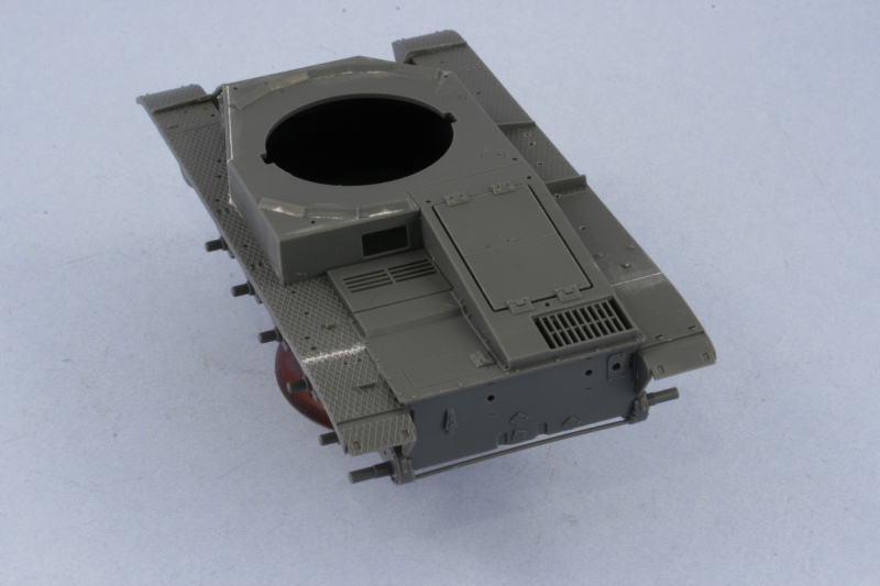
Step 5 begins the work with the upper hull. There are a number of holes that need to be opened up from the underside and, using the kit diagram to insure I only opened the ones needed for this variant, this was easily done using a #68 finger drill. Holes needed to be opened on only one fender side but also the underside of the superstructure roof to take the splash guards in Step 6. The inserts for the side air intake as well as the angled hull sponson were added without issue.

Step 6 adds all the panels to the superstructure as well as the splash guards and fender extensions. I removed all the panels and carefully cleaned up their sprue attachment points and opened up the two holes needed on the driver's side panel to take the splash guard for the view port using the same finger drill from before. A test fit of the panels showed that the panels fit well together but that the driver's plate had a slight gap on the superstructure roof as well as the angled butt joint where it mated up with the rear portion of the hull. This gap was small but noticeable, so some very careful use of Squadron white putty was called for along with strategic sanding to avoid damaging the nicely molded on weld bead detail on the edge of the plates. The other plates didn't need any putty work, only some light sanding to blend in their edges to create the seamless look needed.
The splash guards came next and these presented an unexpected problem during clean-up. Due to the way they are attached to the sprue, the attachment point is actually on the base of the part via a little tab. This works well to preserve the fine angled detail but when I removed the tab with sprue cutters, the slight stress was enough to take part of the edge of the delicate angled portion with it...creating a slight gouge in the process. These were repaired with same targeted putty work once the guards were installed to the hull. Finally, the rear fender extensions were added to complete this step.

Step 7 calls for the upper and lower hulls to be joined, so before I commit to that I'm going to have to do some tests with the link-and-length segments first to see what my options are. If the tracks have to fitted now, then some paint work will be required first before I can proceed to that step.
Step 2 started in with the lower hull, adding the suspension arms for each side. Care has to be taken to keep the parts separate as they are not only handed but the final 5th suspension element is subtly different in terms of the spring angle, so I made sure to attach the first four then the final fifth separately to avoid any accidental mix-ups. The slight mold seam on the suspension springs was carefully removed with a sharp #11 blade. The idler mounts were also installed in their fixed position on both sides. The rounded hull nose plate was then installed and it fit perfectly in with the lower hull. Once the glue had set, I installed the final drive housings along with their trapped poly caps for the sprockets.
I went ahead and skipped Step 3 except for the installation of the rear hull plate since the rest of that step installs the various items from Step 1 to the hull.
Step 4 deals with the installation of the link-and-length tracks so was temporarily skipped...I'm going to see if I can still fit the track lengths in with the upper hull installed or not before committing to doing that...more on that later.
Step 5 begins the work with the upper hull. There are a number of holes that need to be opened up from the underside and, using the kit diagram to insure I only opened the ones needed for this variant, this was easily done using a #68 finger drill. Holes needed to be opened on only one fender side but also the underside of the superstructure roof to take the splash guards in Step 6. The inserts for the side air intake as well as the angled hull sponson were added without issue.
Step 6 adds all the panels to the superstructure as well as the splash guards and fender extensions. I removed all the panels and carefully cleaned up their sprue attachment points and opened up the two holes needed on the driver's side panel to take the splash guard for the view port using the same finger drill from before. A test fit of the panels showed that the panels fit well together but that the driver's plate had a slight gap on the superstructure roof as well as the angled butt joint where it mated up with the rear portion of the hull. This gap was small but noticeable, so some very careful use of Squadron white putty was called for along with strategic sanding to avoid damaging the nicely molded on weld bead detail on the edge of the plates. The other plates didn't need any putty work, only some light sanding to blend in their edges to create the seamless look needed.
The splash guards came next and these presented an unexpected problem during clean-up. Due to the way they are attached to the sprue, the attachment point is actually on the base of the part via a little tab. This works well to preserve the fine angled detail but when I removed the tab with sprue cutters, the slight stress was enough to take part of the edge of the delicate angled portion with it...creating a slight gouge in the process. These were repaired with same targeted putty work once the guards were installed to the hull. Finally, the rear fender extensions were added to complete this step.
Step 7 calls for the upper and lower hulls to be joined, so before I commit to that I'm going to have to do some tests with the link-and-length segments first to see what my options are. If the tracks have to fitted now, then some paint work will be required first before I can proceed to that step.
-
Bill Plunk
- Posts: 1245
- Joined: Wed Sep 28, 2022 10:18 pm
WIP 06-13-2009
Ever just get in a groove with a build and really get rolling? Today was such a day...probably one of the most productive model-building days I've had in a long time in fact.
Picking up from yesterday, I did a check with the top run of tracks and the clearance with the upper fenders and decided I had enough room to work with once the upper and lower hulls were joined. The test fit also revealed to me just how much of the underside of the fenders would be visible, so I went back and filled and sanded all the ejector marks on the underside as a precaution.

With that out of the way, I proceeded to work on Step 7 and join the upper and lower hulls. The fit here is good but the contact surfaces are not very large, so I used some rubber bands as added insurance to get a solid join all around.

Step 7 calls for the installation of the rear engine access hatch as well as the radio operator's hatch. Curiously the engine hatch actually has latch detail on the underside but since it's molded as one piece, you'd have to cut through that if you wanted to show the hatches open. The detail on the hatch is very good and the gap around the perimeter is supposed to be there just like on the real vehicle. After checking references and realizing that the fenders weren't jointed, I carefully filled the slight gap where the fender extensions met the hull from the previous step and sanded down the edges smooth.
Step 7 also adds the glacis plates and large access hatch for the driver. This fit beautifully and just required a little bit of liquid glue at the front to get the weld seam join to look the part. The correct style of view ports for the C were installed for the driver, these are called out properly on the instructions but are right next to the type for the c, A, or B so a double-check is a good idea to be sure you don't accidentally grab the wrong ones. The one piece tow rope/transmission hatch was also added along with the front tow hooks. The front fenders supports were also installed to complete the step after some ejector marks on their rear surfaces were sanded down.

Step 8 takes care of some sub-assemblies in preparation for later steps. These include the 4 part jack, the spare barrel box and lid, the two front headlights with blackout covers, the two-part antenna tray, the three-part tow hitch, and the 4 part muffler. The antenna holder had some ejector marks on the inner surfaces that I sanded down out of an abundance of caution. The muffler required the most work, with it's seam sanded down and some putty added to fill small gaps on either ends where the armored pipe from the engine and the hollow exhaust pipe installed.

Step 9 deals primarily with the rear hull plate details. The muffler is installed along with the rear brake light, the tow pintle, and the rear tow eyes. The PE mesh heat shield cover for the muffler was annealed over a gas burner flame and then carefully curved to shape using a Mission Models Multi-tool. The PE, since it's steel, is stiffer to work worth vs. brass so it took several sessions to get it to shape properly. The hull has small cut-outs molded in to take the mount tabs, so getting it into position was easy with no guess work required. The rear fender supports were also installed along with the mud-flaps. The tool box and spare barrels boxes were installed on the right side fender while the jack went on the left. The radio operator's view port was also installed and, unlike the driver's ports, this one is the earlier c/A/B type and not the C type. It's the only option provided so there was no choice there and is a minor thing in the long-run. Last but not least all the tiny little lifting eyes were added to the upper hull. No spares are available so I worked slowly and one at a time to make sure I didn't have any casualties along the way.

Step 10 deals mostly with the fender gear and I was selective in terms of what I installed and what was left off for later. The left side fender received the antenna tray, the fire extinguisher, and the long pry bar but the shovel, axe, and jack block were left off for later. All of the tools on the right fender were also left off and the front headlights were installed. I added the missing wiring conduit using 0.5mm diameter solder cut to shape and carefully glued down with liquid glue as an added detail.

Step 11 deals with assembling the commander's chair and the interior detail for his hatches. Since I'm not posing the hatches open, I skipped this step entirely.
Step 12 deals with the main armament and the first order of business is to install the MG34 and KwK 30 into the interior mantlet. Since the KwK 30 is molded as all one piece, I removed the molded on barrel portion with sprue cutters and sanded it down smooth. A mount hole was drilled with a pin vise and the Lionmarc turned brass barrel installed. The open sighting view ports were also added to the mantlet along with the circular elevation parts, the elevation parts are not glued. Only one of these receives a poly cap and the result is a very snug, but still movable, fit while the other just fits loosely on the other side elevation pin.

Next was the addition of the external mantlet plate which also serves as the turret front plate. This has to be carefully installed by getting small D-shaped tabs to align with the elevation parts.

The other half of this step is the assembly of the turret itself. The top and bottom halves were joined using a combination of regular and liquid glue and allowed to set up. The splash guard for the commander's hatches and the signal port cover were also added.

The step is completed with the installation of the mantlet and guns into the turret proper. I used a careful combination of liquid glue and regular glue, making sure that the guns could remain movable throughout. Some slight finger pressure was needed in a couple spots but otherwise a very snug fit. The main open sight hatch kept popping loose on me so I decided to pose it in the open position since that gave a larger glue surface. It also has the added benefit of the feel that the vehicle is "crewed" since most of the other hatches aside from the commander's hatch don't have any interior detail and have to be posed closed as a result.

Step 14 deals with the installation of the commander's hatches and the remaining side vision ports. The turret lifting eyes were also added. I also added some weld texture to the missing areas on the angled lower turret plates by carefully scoring the plastic with the tip of a sharp #11 blade. I then came back and sanded it down to make it smaller and more regular...the photo makes the area look a little more pronounced than it actually is.

Step 15 calls for the installation of the turret into the hull as well as the addition of the rear rhomboid number plate. This was added using a drop of CA gel and some liquid glue. I also added an Armorscale 2m brass antenna (trimmed down to fit the 1.4m antenna tray) by removing the stub in the mast and drilling out a small hole and gluing it in place with CA gel. The mast was then installed to the hull side in the down position.

Incredibly as it sounds...this one's now ready for painting!
Picking up from yesterday, I did a check with the top run of tracks and the clearance with the upper fenders and decided I had enough room to work with once the upper and lower hulls were joined. The test fit also revealed to me just how much of the underside of the fenders would be visible, so I went back and filled and sanded all the ejector marks on the underside as a precaution.
With that out of the way, I proceeded to work on Step 7 and join the upper and lower hulls. The fit here is good but the contact surfaces are not very large, so I used some rubber bands as added insurance to get a solid join all around.
Step 7 calls for the installation of the rear engine access hatch as well as the radio operator's hatch. Curiously the engine hatch actually has latch detail on the underside but since it's molded as one piece, you'd have to cut through that if you wanted to show the hatches open. The detail on the hatch is very good and the gap around the perimeter is supposed to be there just like on the real vehicle. After checking references and realizing that the fenders weren't jointed, I carefully filled the slight gap where the fender extensions met the hull from the previous step and sanded down the edges smooth.
Step 7 also adds the glacis plates and large access hatch for the driver. This fit beautifully and just required a little bit of liquid glue at the front to get the weld seam join to look the part. The correct style of view ports for the C were installed for the driver, these are called out properly on the instructions but are right next to the type for the c, A, or B so a double-check is a good idea to be sure you don't accidentally grab the wrong ones. The one piece tow rope/transmission hatch was also added along with the front tow hooks. The front fenders supports were also installed to complete the step after some ejector marks on their rear surfaces were sanded down.
Step 8 takes care of some sub-assemblies in preparation for later steps. These include the 4 part jack, the spare barrel box and lid, the two front headlights with blackout covers, the two-part antenna tray, the three-part tow hitch, and the 4 part muffler. The antenna holder had some ejector marks on the inner surfaces that I sanded down out of an abundance of caution. The muffler required the most work, with it's seam sanded down and some putty added to fill small gaps on either ends where the armored pipe from the engine and the hollow exhaust pipe installed.
Step 9 deals primarily with the rear hull plate details. The muffler is installed along with the rear brake light, the tow pintle, and the rear tow eyes. The PE mesh heat shield cover for the muffler was annealed over a gas burner flame and then carefully curved to shape using a Mission Models Multi-tool. The PE, since it's steel, is stiffer to work worth vs. brass so it took several sessions to get it to shape properly. The hull has small cut-outs molded in to take the mount tabs, so getting it into position was easy with no guess work required. The rear fender supports were also installed along with the mud-flaps. The tool box and spare barrels boxes were installed on the right side fender while the jack went on the left. The radio operator's view port was also installed and, unlike the driver's ports, this one is the earlier c/A/B type and not the C type. It's the only option provided so there was no choice there and is a minor thing in the long-run. Last but not least all the tiny little lifting eyes were added to the upper hull. No spares are available so I worked slowly and one at a time to make sure I didn't have any casualties along the way.
Step 10 deals mostly with the fender gear and I was selective in terms of what I installed and what was left off for later. The left side fender received the antenna tray, the fire extinguisher, and the long pry bar but the shovel, axe, and jack block were left off for later. All of the tools on the right fender were also left off and the front headlights were installed. I added the missing wiring conduit using 0.5mm diameter solder cut to shape and carefully glued down with liquid glue as an added detail.
Step 11 deals with assembling the commander's chair and the interior detail for his hatches. Since I'm not posing the hatches open, I skipped this step entirely.
Step 12 deals with the main armament and the first order of business is to install the MG34 and KwK 30 into the interior mantlet. Since the KwK 30 is molded as all one piece, I removed the molded on barrel portion with sprue cutters and sanded it down smooth. A mount hole was drilled with a pin vise and the Lionmarc turned brass barrel installed. The open sighting view ports were also added to the mantlet along with the circular elevation parts, the elevation parts are not glued. Only one of these receives a poly cap and the result is a very snug, but still movable, fit while the other just fits loosely on the other side elevation pin.
Next was the addition of the external mantlet plate which also serves as the turret front plate. This has to be carefully installed by getting small D-shaped tabs to align with the elevation parts.
The other half of this step is the assembly of the turret itself. The top and bottom halves were joined using a combination of regular and liquid glue and allowed to set up. The splash guard for the commander's hatches and the signal port cover were also added.
The step is completed with the installation of the mantlet and guns into the turret proper. I used a careful combination of liquid glue and regular glue, making sure that the guns could remain movable throughout. Some slight finger pressure was needed in a couple spots but otherwise a very snug fit. The main open sight hatch kept popping loose on me so I decided to pose it in the open position since that gave a larger glue surface. It also has the added benefit of the feel that the vehicle is "crewed" since most of the other hatches aside from the commander's hatch don't have any interior detail and have to be posed closed as a result.
Step 14 deals with the installation of the commander's hatches and the remaining side vision ports. The turret lifting eyes were also added. I also added some weld texture to the missing areas on the angled lower turret plates by carefully scoring the plastic with the tip of a sharp #11 blade. I then came back and sanded it down to make it smaller and more regular...the photo makes the area look a little more pronounced than it actually is.
Step 15 calls for the installation of the turret into the hull as well as the addition of the rear rhomboid number plate. This was added using a drop of CA gel and some liquid glue. I also added an Armorscale 2m brass antenna (trimmed down to fit the 1.4m antenna tray) by removing the stub in the mast and drilling out a small hole and gluing it in place with CA gel. The mast was then installed to the hull side in the down position.
Incredibly as it sounds...this one's now ready for painting!
-
Bill Plunk
- Posts: 1245
- Joined: Wed Sep 28, 2022 10:18 pm
WIP 06-14-2009
Weather was perfect for painting today, so the first order of business was the usual prep. The turret was separated from the hull and mounted on a cardboard tube with strips of blue painter's tape for easier handling of both the turret and the hull. The road wheels, idlers, and return rollers were mounted on toothpicks with only the return rollers needing some blue tack putty to hold them in place since the others had the poly caps.

Everything was primed using Model Master enamel Italian Dark Brown. This was particularly helpful since the Tamiya plastic is already dark gray to insure that all the plastic surfaces were painted before applying the base coat. The base coat of Panzer Schwarzgrau was then added in multiple passes to build it up over the primer coat.

The next step applied some highlights and variation in the form of about an 80/20 mix of Panzer Schwarzgrau/Light Gray in a reverse shading pattern. Some of the areas were going to be covered with the camo pattern but that's ok, the idea was to get the gray areas looking the way I wanted to first.

Since the ordered scheme in effect at the time of the Polish campaign called for a 2/3 Dunkelgrau 1/3 Dunkelbraun scheme, I used Model Master enamel Panzer Schokoladenbraun as the Dunkelbraun and applied it freehand. I tried to break up the pattern a bit and also adhere to the required ratio even though the temptation was there to go 50-50. Given the overall size of the vehicle, it was a balancing act and I worked slowly and deliberately since the Tamiya instructions were no help at all in terms of the pattern.

The road wheels were also painted at this stage in preparation for mounting. They were also primered with the Italian Dark Brown and then the rubber portions painted using enamel Gunmetal and then the hubs painted using a circle template. In the 2/3-1/3 spirit, I painted 6 in Dunkelgrau and 4 in Dunkelbraun. The return rollers also had their hubs painted using the same method.

This will sit now until next weekend and then it's on to the tracks and other remaining details.
Everything was primed using Model Master enamel Italian Dark Brown. This was particularly helpful since the Tamiya plastic is already dark gray to insure that all the plastic surfaces were painted before applying the base coat. The base coat of Panzer Schwarzgrau was then added in multiple passes to build it up over the primer coat.
The next step applied some highlights and variation in the form of about an 80/20 mix of Panzer Schwarzgrau/Light Gray in a reverse shading pattern. Some of the areas were going to be covered with the camo pattern but that's ok, the idea was to get the gray areas looking the way I wanted to first.
Since the ordered scheme in effect at the time of the Polish campaign called for a 2/3 Dunkelgrau 1/3 Dunkelbraun scheme, I used Model Master enamel Panzer Schokoladenbraun as the Dunkelbraun and applied it freehand. I tried to break up the pattern a bit and also adhere to the required ratio even though the temptation was there to go 50-50. Given the overall size of the vehicle, it was a balancing act and I worked slowly and deliberately since the Tamiya instructions were no help at all in terms of the pattern.
The road wheels were also painted at this stage in preparation for mounting. They were also primered with the Italian Dark Brown and then the rubber portions painted using enamel Gunmetal and then the hubs painted using a circle template. In the 2/3-1/3 spirit, I painted 6 in Dunkelgrau and 4 in Dunkelbraun. The return rollers also had their hubs painted using the same method.
This will sit now until next weekend and then it's on to the tracks and other remaining details.
-
Bill Plunk
- Posts: 1245
- Joined: Wed Sep 28, 2022 10:18 pm
WIP 06-21-2009
This weekend was kind of a slow model-building weekend...I guess that's appropriate considering how much got done last weekend! I did make progress on the detail front with the first order of business being to paint up all the tools and get them installed. This followed my usual pattern with the metal portions painted with Non-buffing Metalizer Gunmetal and lightly dry brushed with Steel. The wood portions were painted first with my custom "wood" color and then given a light wash of Leather followed by a strategic dusting of Burnt Umber artist pastels. The jack block was also counter dry brushed with the "wood" color to give it more variety. The wire cutters had their Bakelite handles painted with Italian Dark Brown and the rubber end caps painted with enamel Gunmetal. The tools were then installed to both fenders.


Next up was the final hurdle, the tracks! This is what the instruction diagram looks like back in Step 4.

This process turned out to be longer than I thought it would be. All of the links and lengths sections were removed from the sprues and cleaned up. Since the contact surfaces are so small due to the small size of the Pz II links, I went ahead and formed the curved parts first. To do this, I used the sprockets and idlers as, well, formers, and glued the curved sections together and then left them to dry overnight resting on their respective surfaces.

Once those had set up, I attached the sprocket curved portion to the angled length portion and glued that into the long base piece. This was done for both sides so that they would form as a single piece that could still be removed for painting. This was possible due to the fact that the sprocket could remain movable courtesy of the polycap.
The different sections were then base coated with Non-buffing Metalizer Gunmetal, heavily dry brushed with Steel, and then given a wash of Burnt Umber to prepare them for installation.

The final steps involved getting the remaining lengths to join up into a single track run. To accomplish this, I first positioned the top run and then glued the idlers into place but didn't yet glue the top run onto the idlers. A little bit of slack is needed to play around with to get the front and rear portions lined up, so it's best to do this last. Once the top run had set for about 1 hour, I then joined the bottom run up at the idler to the top. At this stage it was no longer desirable that the sprockets and idlers be able to rotate as they kept putting a little bit of "play" into the way the tracks were setting, so I applied some liquid glue to their inner contact surfaces with the mount arms and they are now fixed firmly into position. Then, using some strategic toothpicks to hold it down and prevent floating, the top run was glued down to the return rollers.

Process was repeated for the other side and after several hours (much of it spent waiting for glue to set up), both tracks were finally installed.

Next up will be adding the markings and then onto the weathering stage!
Next up was the final hurdle, the tracks! This is what the instruction diagram looks like back in Step 4.
This process turned out to be longer than I thought it would be. All of the links and lengths sections were removed from the sprues and cleaned up. Since the contact surfaces are so small due to the small size of the Pz II links, I went ahead and formed the curved parts first. To do this, I used the sprockets and idlers as, well, formers, and glued the curved sections together and then left them to dry overnight resting on their respective surfaces.
Once those had set up, I attached the sprocket curved portion to the angled length portion and glued that into the long base piece. This was done for both sides so that they would form as a single piece that could still be removed for painting. This was possible due to the fact that the sprocket could remain movable courtesy of the polycap.
The different sections were then base coated with Non-buffing Metalizer Gunmetal, heavily dry brushed with Steel, and then given a wash of Burnt Umber to prepare them for installation.
The final steps involved getting the remaining lengths to join up into a single track run. To accomplish this, I first positioned the top run and then glued the idlers into place but didn't yet glue the top run onto the idlers. A little bit of slack is needed to play around with to get the front and rear portions lined up, so it's best to do this last. Once the top run had set for about 1 hour, I then joined the bottom run up at the idler to the top. At this stage it was no longer desirable that the sprockets and idlers be able to rotate as they kept putting a little bit of "play" into the way the tracks were setting, so I applied some liquid glue to their inner contact surfaces with the mount arms and they are now fixed firmly into position. Then, using some strategic toothpicks to hold it down and prevent floating, the top run was glued down to the return rollers.
Process was repeated for the other side and after several hours (much of it spent waiting for glue to set up), both tracks were finally installed.
Next up will be adding the markings and then onto the weathering stage!
-
Bill Plunk
- Posts: 1245
- Joined: Wed Sep 28, 2022 10:18 pm
WIP 06-24-2009
There hasn't been much in the way of good stuff on TV the past couple of days so I decided to use the time in the evenings to get the decals on. First up was the usual sealing coat of Future applied by airbrush. This was allowed to air dry for a couple of hours and then the work began with the decals.
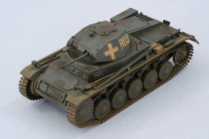
I opted for the "R03" designation since I had a reference photo to work off of from "Panzer Vor!" Vol 1. The kit markings are pure white even though it looks like the photo has had mud smeared on the markings so I'm going to have some fun in how I approach that one.

The decals were applied using Solvaset and, due to the complex surfaces that most had to conform to, several doses and some careful prodding with a soft brush were necessary to get them all to settle down properly. The decals did tear slightly in a couple of places so some touch up with some Flat White paint was in order but nothing too dramatic. A second coat of Future was air brushed to seal in and protect the markings and will be allowed to sit overnight at a minimum before the weathering process can begin.


I opted for the "R03" designation since I had a reference photo to work off of from "Panzer Vor!" Vol 1. The kit markings are pure white even though it looks like the photo has had mud smeared on the markings so I'm going to have some fun in how I approach that one.
The decals were applied using Solvaset and, due to the complex surfaces that most had to conform to, several doses and some careful prodding with a soft brush were necessary to get them all to settle down properly. The decals did tear slightly in a couple of places so some touch up with some Flat White paint was in order but nothing too dramatic. A second coat of Future was air brushed to seal in and protect the markings and will be allowed to sit overnight at a minimum before the weathering process can begin.
-
Bill Plunk
- Posts: 1245
- Joined: Wed Sep 28, 2022 10:18 pm
WIP 06-27-2009
With the decals on, the next step was to proceed with the weathering. Since the camo colors are dark to begin with, I first applied an overall wash of enamel Raw Sienna with a large round sable brush.

This was followed by dot filters of enamel Flat Sea Blue, Flat White, and Italian Dark Brown to fade and add variation to the overall finish. The dots were blended together with a square tip blender brush moistened with clean thinner. I liked the results on the fenders from the Raw Sienna wash so I left those areas alone, applying the fading/streaking only to the hull and turret surfaces.

The Raw Sienna was a good compliment to the base coat colors and I applied it again as a pin wash to all of the raised detail and panel lines to simulate dust/dirt accumulation. I also used it to simulate the "mud" on the turret crosses and numbers by carefully building it up with multiple applications and fine-tuning along the way. I didn't want it so heavy that it obscured the underlying white totally and this required several attempts before I got it to look the way I wanted.


The entire vehicle was then given a sealing coat of Testors Lusterless Flat via spray can and allowed to dry for an hour before starting in with the pigments. I used Mig Europe Dust combined with regular tap water with a touch of dish washing soap added to break the surface tension. This wet mix was applied to the lower hull, running gear, and fender edges and then allowed to air dry.

The next step involved removing the excess pigment using a round stiff-bristled brush. I wore a dust/sanding mask during this phase to avoid inhaling the very fine pigment particles.

The next adjustment was done using a combination of wet and dry q-tips to further remove and position the pigments in the desired locations.

That completed the build and then it was off to the photo booth!


This was followed by dot filters of enamel Flat Sea Blue, Flat White, and Italian Dark Brown to fade and add variation to the overall finish. The dots were blended together with a square tip blender brush moistened with clean thinner. I liked the results on the fenders from the Raw Sienna wash so I left those areas alone, applying the fading/streaking only to the hull and turret surfaces.
The Raw Sienna was a good compliment to the base coat colors and I applied it again as a pin wash to all of the raised detail and panel lines to simulate dust/dirt accumulation. I also used it to simulate the "mud" on the turret crosses and numbers by carefully building it up with multiple applications and fine-tuning along the way. I didn't want it so heavy that it obscured the underlying white totally and this required several attempts before I got it to look the way I wanted.
The entire vehicle was then given a sealing coat of Testors Lusterless Flat via spray can and allowed to dry for an hour before starting in with the pigments. I used Mig Europe Dust combined with regular tap water with a touch of dish washing soap added to break the surface tension. This wet mix was applied to the lower hull, running gear, and fender edges and then allowed to air dry.
The next step involved removing the excess pigment using a round stiff-bristled brush. I wore a dust/sanding mask during this phase to avoid inhaling the very fine pigment particles.
The next adjustment was done using a combination of wet and dry q-tips to further remove and position the pigments in the desired locations.
That completed the build and then it was off to the photo booth!
-
Bill Plunk
- Posts: 1245
- Joined: Wed Sep 28, 2022 10:18 pm
Publication March 2010
This build is also featured in the Scale Military Modeller International March 2010 Issue on pp. 66-68

