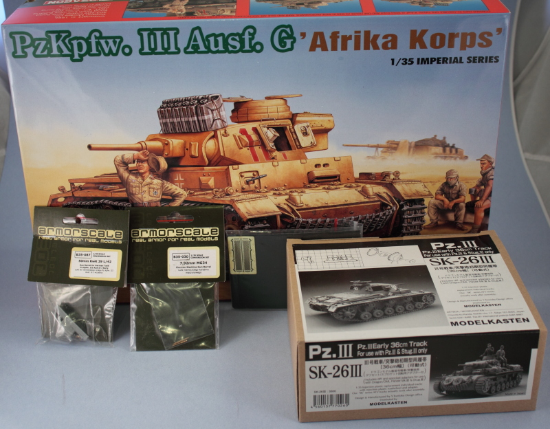
Dragon Imperial Series Pzkpfw III Ausf. G Afrika Korps (2010)
-
Bill Plunk
- Posts: 1245
- Joined: Wed Sep 28, 2022 10:18 pm
Dragon Imperial Series Pzkpfw III Ausf. G Afrika Korps (2010)
Build log for Dragon Imperial Series kit #9032 Pzkpfw III Ausf G 'Afrika Korps'.
-
Bill Plunk
- Posts: 1245
- Joined: Wed Sep 28, 2022 10:18 pm
WIP 12-13-2009
I started work on this project yesterday and between then and today managed to make some decent headway. Since this is an older kit, the parts clean-up is higher with mold seams, flash, etc. taking more time to resolve than you would expect with a modern kit but nothing that basic model skills can't handle.
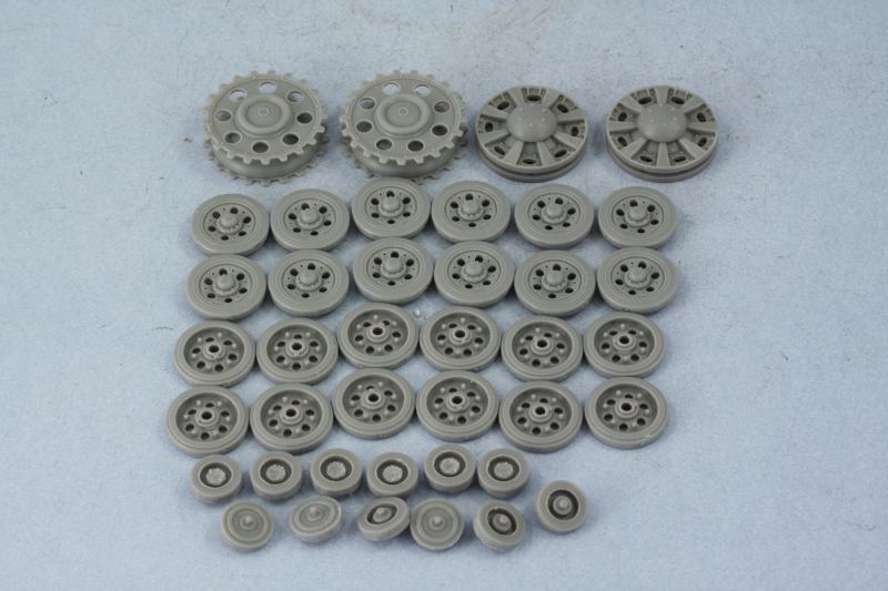
I started where most kits start with Step 1 dealing with all of the road wheels, the return rollers, sprockets, and idlers. The road wheel halves and return roller halves were left un-assembled to make it easier to paint and detail them later. Each of the halves had its mold seam sanded down with a sanding twig on the rubber portions and the external half of the return rollers had a prominent ejector mark on their faces. These were carefully removed using the tip of a round needle file since they are in a particularly tough spot to work in.
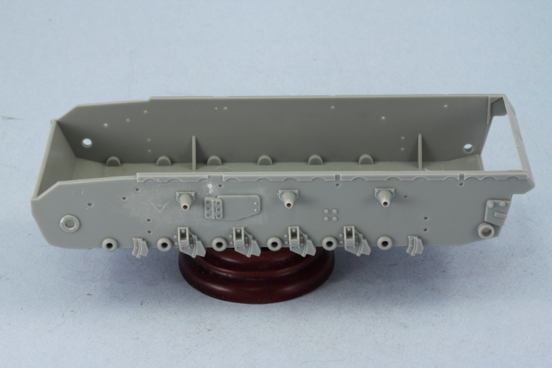
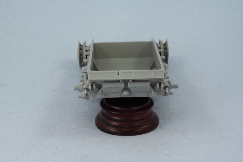
Moving on to Step 2, this deals with the lower hull and suspension. Since the hull is one that DML uses/re-uses in several Pz III/StuG III kits, there are some surgical modifications necessary to make it suitable for a III-G and the instructions call these out. The first return roller mount on either side that is molded as part of the hull has to be removed and replaced with an add-on part to put all the return rollers evenly spaced and level with each other in order to achieve the correct early Pz III arrangement. I cut down the molded-on mount with sprue cutters and then carefully removed the rest with a #11 knife, finally sanding down the remnants until the hull was smooth. Using a metal ruler as a guide, the new mount was installed at the correct height and spacing. One of the mount holes that isn't used was filled with putty and sanded down and I also removed the molded-on locator line for the crew escape hatches with a micro-chisel and sanded it down before installing the hatches. Last but not least, the mount post for the final drive housings was cut down in order to make use of the MK parts that allow the sprocket to rotate instead of installing static as the kit parts are designed.
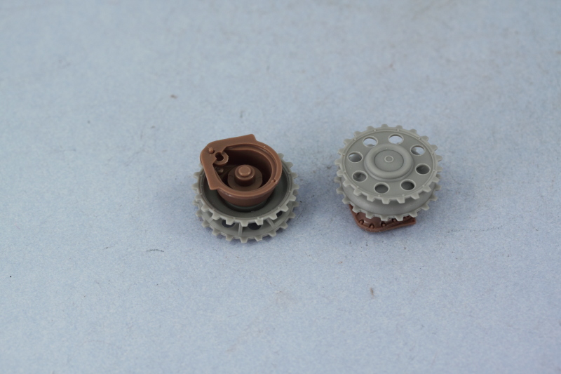
Speaking of the MK parts, I replaced the final drive housing with the MK parts and adapters and added the sprockets to insure everything would rotate freely before installing them to the hull.
The rest of the suspension was then installed as called for in Step 2. The instructions have an error in that parts B13 and B14 are reversed in terms of which side they install to but that was easily worked out and corrected. For the idler, I carefully assembled the idler mount so that the tension arm rod could remain movable and didn't glue the base of the mount to the hull. This allows the idler mount to be slightly movable and will come in handy later on when working with the MK tracks to get just the right tension arrangement when those are mounted.
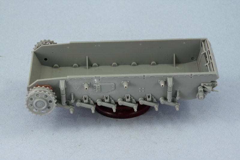
Step 2 also calls for the installation of the rear hull plate and the air exhaust vents. These installed smoothly and without major issues and I added the rear mufflers as well. The exhaust pipes were molded partially hollow but I decided to drill these out a little deeper using a micro drill bit and pin vise to give them a more realistic appearance. The rear tow pintles were also added and these had some ejector marks on their outward faces that had to be carefully removed before installation.
Step 3 calls for the road wheels to be installed and Step 4 for the tracks so both of these will be skipped for now. The next steps will deal with the upper hull but that will have to wait until next weekend!
I started where most kits start with Step 1 dealing with all of the road wheels, the return rollers, sprockets, and idlers. The road wheel halves and return roller halves were left un-assembled to make it easier to paint and detail them later. Each of the halves had its mold seam sanded down with a sanding twig on the rubber portions and the external half of the return rollers had a prominent ejector mark on their faces. These were carefully removed using the tip of a round needle file since they are in a particularly tough spot to work in.
Moving on to Step 2, this deals with the lower hull and suspension. Since the hull is one that DML uses/re-uses in several Pz III/StuG III kits, there are some surgical modifications necessary to make it suitable for a III-G and the instructions call these out. The first return roller mount on either side that is molded as part of the hull has to be removed and replaced with an add-on part to put all the return rollers evenly spaced and level with each other in order to achieve the correct early Pz III arrangement. I cut down the molded-on mount with sprue cutters and then carefully removed the rest with a #11 knife, finally sanding down the remnants until the hull was smooth. Using a metal ruler as a guide, the new mount was installed at the correct height and spacing. One of the mount holes that isn't used was filled with putty and sanded down and I also removed the molded-on locator line for the crew escape hatches with a micro-chisel and sanded it down before installing the hatches. Last but not least, the mount post for the final drive housings was cut down in order to make use of the MK parts that allow the sprocket to rotate instead of installing static as the kit parts are designed.
Speaking of the MK parts, I replaced the final drive housing with the MK parts and adapters and added the sprockets to insure everything would rotate freely before installing them to the hull.
The rest of the suspension was then installed as called for in Step 2. The instructions have an error in that parts B13 and B14 are reversed in terms of which side they install to but that was easily worked out and corrected. For the idler, I carefully assembled the idler mount so that the tension arm rod could remain movable and didn't glue the base of the mount to the hull. This allows the idler mount to be slightly movable and will come in handy later on when working with the MK tracks to get just the right tension arrangement when those are mounted.
Step 2 also calls for the installation of the rear hull plate and the air exhaust vents. These installed smoothly and without major issues and I added the rear mufflers as well. The exhaust pipes were molded partially hollow but I decided to drill these out a little deeper using a micro drill bit and pin vise to give them a more realistic appearance. The rear tow pintles were also added and these had some ejector marks on their outward faces that had to be carefully removed before installation.
Step 3 calls for the road wheels to be installed and Step 4 for the tracks so both of these will be skipped for now. The next steps will deal with the upper hull but that will have to wait until next weekend!
-
Bill Plunk
- Posts: 1245
- Joined: Wed Sep 28, 2022 10:18 pm
Reference Note 12-19-2009
After much thought and deliberation, I've decided to use the reference photo below found in Trojca's Sdkfz 141 Pzkpfw III and will attempt to recreate some of the key features shown. Specifically, I will be modifying the fender to remove the forward section and rearranging the gear on the fenders as well.
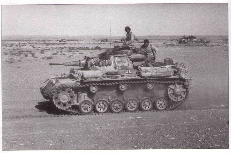
Interestingly enough, the MK track set box has a photo of a build of this same vehicle replicating everything including the stowage and figures that will also provide some valuable insight. Work is getting ready to start on the upper hull and fenders so this was the right point to make a decision one way or the other!
Interestingly enough, the MK track set box has a photo of a build of this same vehicle replicating everything including the stowage and figures that will also provide some valuable insight. Work is getting ready to start on the upper hull and fenders so this was the right point to make a decision one way or the other!
-
Bill Plunk
- Posts: 1245
- Joined: Wed Sep 28, 2022 10:18 pm
WIP 12-19-2009
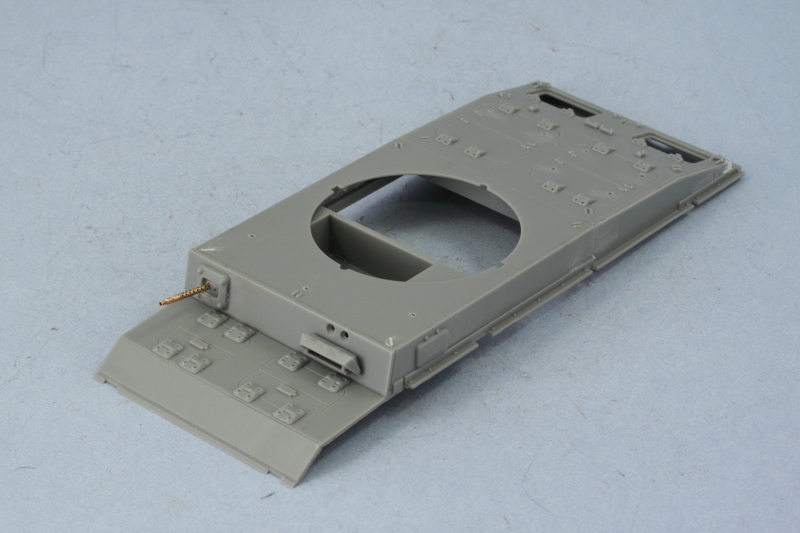
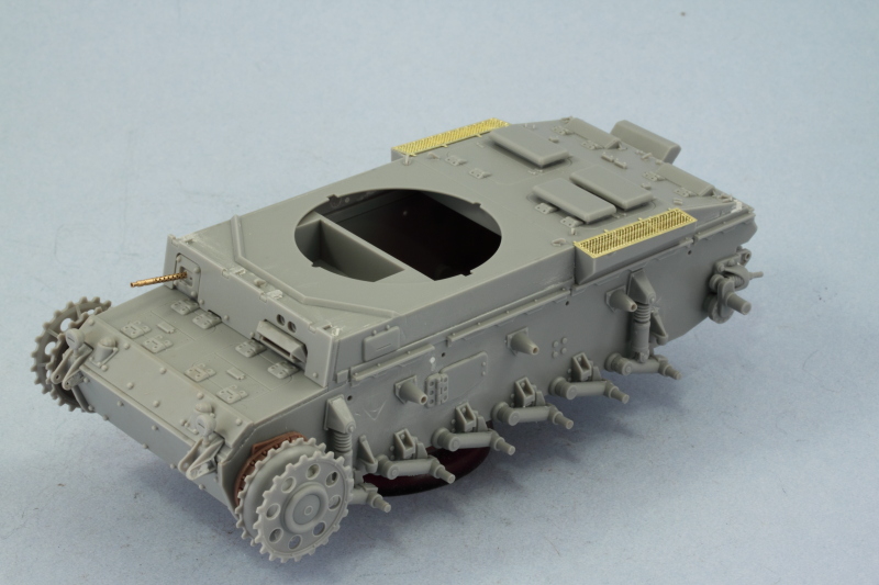
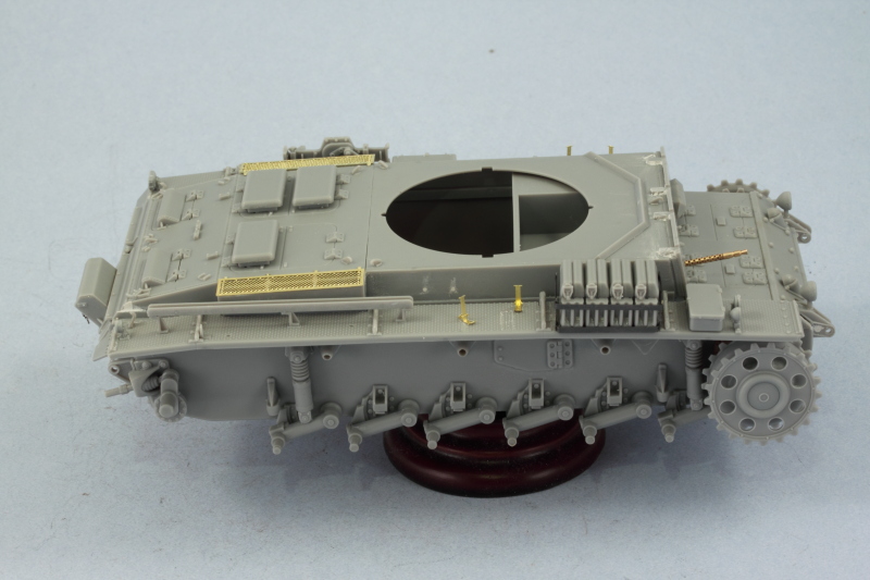
Progress was good today, I started in on the upper hull since that was the next item of business in the instructions. The upper hull foundation is actually that of a StuG III so to convert it over to a Pz III hull there are several modifications that have to be done. Step 5 outlines most of these although there are some that are also called out in Step 8 that I went ahead and did at this point in time just because it's easier to do it now vs. later. These modifications include adding the hull side panels appropriate for the Pz III but these have several bolt heads that have to be shaved off as well as some locator marks that aren't used on both sides. This was easily taken care of with a sharp #11 blade and a little bit of sanding. At the rear hull there are some indentations on both sides that need to be filled with putty and there are 6 holes that need to be opened up in the engine deck hatches to take the Tropen cooling vent covers in a later step. Last but not least, the triangular stops for the engine hatches also needed to be removed and sanded down.
For the right side hull panel, two holes have to be opened up to take the armored port cover there for the hull gunner's position, unfortunately I wasn't paying too close attention and opened up the two holes at the rear of the panel instead of the two at the front...so the wrong holes were carefully puttied over and the right holes opened and the port installed. The front hull brake access hatch panel was also added at this point to complete the step.
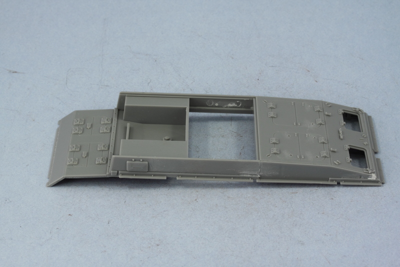
Step 6 adds the hull roof and the superstructure front plate and both of these require modification to conform to the G layout. The roof needs the two corner lifting hook mounts removed and the indentations for the hook itself puttied and sanded. Three holes need to be opened up for the turret splash ring to be added later. The front plate requires some significant surgery as it doesn't have the square opening for the MG34 ball mount. The opening is outlined on the back side but it has to be cut out, so I drilled out small holes in each of the corners and carefully removed the square with a razor saw. The ball mount was added to the plate and the glue allowed to set up.
Before I installed the plate to the hull, I test fit the brass Armorscale MG34 barrel and needed to enlarge the opening for the barrel to install properly. This was done with a combination of a drill bit and pin vise and a round needle file to get the diameter required both front and back on the mount until the barrel fit snugly. The G featured the perforated type of cooling jacket and the kit part just didn't have the level of detail needed to do this justice and I checked the length of the barrel against the scale plans in Panzer Tracts 3-2 before gluing into place with CA gel. Due to the tight space behind the plate, I had to trim down the rear portion of the barrel a couple of mm with side cutters so that the plate and MG would line up properly.
I added the armored visor for the driver in the up position and then glued the hull roof into place using liquid glue to get a good join along the perimeter. While Step 6 also calls for the installation of the bolt-on armor for the glacis plate, I decided to wait to do that until I added the nose plate and the upper and lower hull were joined together to insure proper alignment of all the various components.
That led me to Step 7 which joins the upper and lower hull components together. The mating surfaces aren't large between them and some flash on the lower hull needed to be trimmed away in different places to get a good join. I used regular glue and a series of rubber bands to secure them together and left it to dry for a couple of hours. I also added the bolt on panels for the glacis and nose as well as the armored covers for the brake vents.
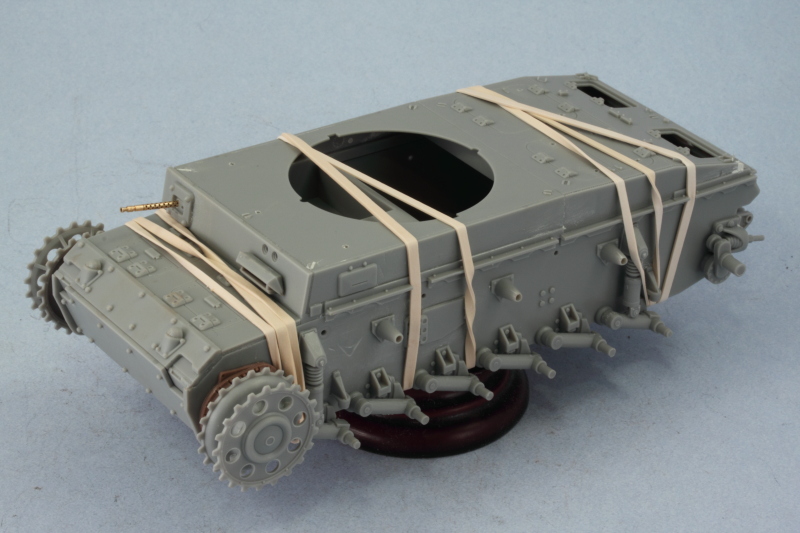
Once the join was set, I removed the bandages and the patient came through just fine. The remaining items from Step 7 were added in the form of the superstructure front bolt-on plate, splash guard for the turret, and lifting hooks for the hull roof. The bolt-on plate fit generally well but some small gaps were the roof tabs met the hull roof needed some putty to fill them and simulate the welded on nature of the connection.
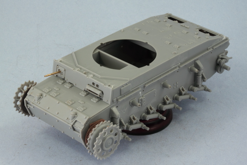
Next up will be working on the rear hull and fenders!
For the right side hull panel, two holes have to be opened up to take the armored port cover there for the hull gunner's position, unfortunately I wasn't paying too close attention and opened up the two holes at the rear of the panel instead of the two at the front...so the wrong holes were carefully puttied over and the right holes opened and the port installed. The front hull brake access hatch panel was also added at this point to complete the step.
Step 6 adds the hull roof and the superstructure front plate and both of these require modification to conform to the G layout. The roof needs the two corner lifting hook mounts removed and the indentations for the hook itself puttied and sanded. Three holes need to be opened up for the turret splash ring to be added later. The front plate requires some significant surgery as it doesn't have the square opening for the MG34 ball mount. The opening is outlined on the back side but it has to be cut out, so I drilled out small holes in each of the corners and carefully removed the square with a razor saw. The ball mount was added to the plate and the glue allowed to set up.
Before I installed the plate to the hull, I test fit the brass Armorscale MG34 barrel and needed to enlarge the opening for the barrel to install properly. This was done with a combination of a drill bit and pin vise and a round needle file to get the diameter required both front and back on the mount until the barrel fit snugly. The G featured the perforated type of cooling jacket and the kit part just didn't have the level of detail needed to do this justice and I checked the length of the barrel against the scale plans in Panzer Tracts 3-2 before gluing into place with CA gel. Due to the tight space behind the plate, I had to trim down the rear portion of the barrel a couple of mm with side cutters so that the plate and MG would line up properly.
I added the armored visor for the driver in the up position and then glued the hull roof into place using liquid glue to get a good join along the perimeter. While Step 6 also calls for the installation of the bolt-on armor for the glacis plate, I decided to wait to do that until I added the nose plate and the upper and lower hull were joined together to insure proper alignment of all the various components.
That led me to Step 7 which joins the upper and lower hull components together. The mating surfaces aren't large between them and some flash on the lower hull needed to be trimmed away in different places to get a good join. I used regular glue and a series of rubber bands to secure them together and left it to dry for a couple of hours. I also added the bolt on panels for the glacis and nose as well as the armored covers for the brake vents.
Once the join was set, I removed the bandages and the patient came through just fine. The remaining items from Step 7 were added in the form of the superstructure front bolt-on plate, splash guard for the turret, and lifting hooks for the hull roof. The bolt-on plate fit generally well but some small gaps were the roof tabs met the hull roof needed some putty to fill them and simulate the welded on nature of the connection.
Next up will be working on the rear hull and fenders!
-
Bill Plunk
- Posts: 1245
- Joined: Wed Sep 28, 2022 10:18 pm
WIP 12-20-2009
More progress was made today although not as much as I had expected and I blame it all on the NFL! The Niners game got moved to an afternoon slot due to all the snow in Philadelphia and that totally wrecked my day schedule plans. That's my story and I'm stickin' to it!
I did manage to complete Step 8 despite losing quite a bit of time assembling the Voyager smoke candle rack only to not be able to use it in the end. The rod that Voyager provided that is crucial to securing all the parts together was the wrong diameter and all I had was some brass rod to replace it with. That turned out to be too stiff and ripped out some of the delicate parts while I was trying to assemble it so I salvaged the smoke candles themselves and the chain and mated that up with the kit parts. The kit doesn't include the candles so that's the critical part to add here anyway IMHO.
I also installed the engine deck hatches and the Tropen vent covers along with the lifting hooks for the rear deck. Last but not least, I installed the crank starter port cover using part C14 instead of the kit directed A43. A43 is the wrong style for the G but fortunately the right part is available on the sprues, just not called out properly.
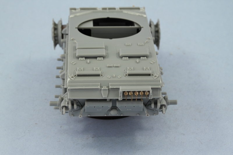
Step 9 was also finished today, this called for the installation of the side air intakes and the front tow points. The side intakes had a little bit of flash that needed to be removed on the insides and some sanding was necessary to smooth down the tops to allow the Aber PE screens to fit properly. The screens were added with some CA gel and the intakes installed into position.
The front tow points required a little bit of work before they could be installed. They had ejector marks on their outer faces that needed putty and sanding to correct and also some sanding at the top to remove the join seam that would be visible there. The points installed without issue and I went ahead and added the front headlights as well even those aren't called for until Step 12 to round things out.
Didn't get to the fenders yet since those will require a lot of rework and shuffling of gear, that's up next on the agenda.
I did manage to complete Step 8 despite losing quite a bit of time assembling the Voyager smoke candle rack only to not be able to use it in the end. The rod that Voyager provided that is crucial to securing all the parts together was the wrong diameter and all I had was some brass rod to replace it with. That turned out to be too stiff and ripped out some of the delicate parts while I was trying to assemble it so I salvaged the smoke candles themselves and the chain and mated that up with the kit parts. The kit doesn't include the candles so that's the critical part to add here anyway IMHO.
I also installed the engine deck hatches and the Tropen vent covers along with the lifting hooks for the rear deck. Last but not least, I installed the crank starter port cover using part C14 instead of the kit directed A43. A43 is the wrong style for the G but fortunately the right part is available on the sprues, just not called out properly.
Step 9 was also finished today, this called for the installation of the side air intakes and the front tow points. The side intakes had a little bit of flash that needed to be removed on the insides and some sanding was necessary to smooth down the tops to allow the Aber PE screens to fit properly. The screens were added with some CA gel and the intakes installed into position.
The front tow points required a little bit of work before they could be installed. They had ejector marks on their outer faces that needed putty and sanding to correct and also some sanding at the top to remove the join seam that would be visible there. The points installed without issue and I went ahead and added the front headlights as well even those aren't called for until Step 12 to round things out.
Didn't get to the fenders yet since those will require a lot of rework and shuffling of gear, that's up next on the agenda.
-
Bill Plunk
- Posts: 1245
- Joined: Wed Sep 28, 2022 10:18 pm
WIP 12-23-2009
I started an extended Christmas vacation yesterday so was able to get some more time in on this one as a result. Work continued with the fenders and focused in on Steps 10-14.
To begin with, the instructions are not quite accurate in terms of the tool layout particularly on the left hand fender to represent the stowage as seen on a standard G. The instructions call for the jack block to be installed at the front behind the Notek light when in fact it belongs on the rear fender and the jack's position as well as the fire extinguisher's are not placed correctly on the second-to-last section. In that case, the jack should be moved forward to the point that the "claw" end overhangs the fender support rod slightly and the fire extinguisher moved to the rear of the same panel instead of the front. These mods are easily done without too much trouble, just a matter of filling the mount holes with putty and clipping off the pins and gluing the parts in the right positions. I replaced the kit-supplied FE with a better detailed spare from a DML Smart Kit from the spares bin.
Other modifications were called for in terms of removing the entire first full section of the fender to replicate the missing portion seen in the reference photo for this particular vehicle. This was done using sprue cutters and then carefully trimming down the remainder with a #11 blade in order to leave the mount tabs for the fender support in place at the junction of the lost section and remaining fender. This vehicle also had a spare road wheel mounted next to the tool box so this required moving the S-hooks forward one section and placing them next to the wire cutters. I used some generic Griffon clamps and "clean" S-hooks without molded on clamps also drawn from the spares bin. The photo also shows that the rear fenders were removed, so this was also cut down using sprue cutters and the stub plate added courtesy of spare parts from the DML Pz III N Smart Kit.
Other kit parts were also replaced with better detailed items including the jack block with one from a Tamiya Pz III L, the rear Notek light and spare road wheel from the DML Pz III-N Smart Kit, and wire cutters from the spares bin (these had to be trimmed slightly to fit the Griffon clamp).
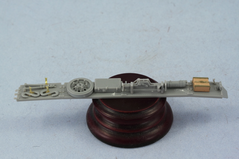
The fender braces were added and then the fender was installed to the hull. I also found some spare wing-nuts while digging around in the spares bin and added a couple of those to the jack mount for a little extra detail. After reviewing the exposed area of the hull around the drive sprocket, I decided to use some putty and add a little bit of weld detail to the plate joins there as well.
The right side fender was not quite as complicated an area to work with...although it too needed some modifications. The rear mud flap was removed to match the left side and the stub plate added. The brake light was replaced with a modified spare part from the DML Pz III N kit that had better detail, ditto for the width indicator light and siren at the front of the fender. The front mud flap was carefully cut down and removed as well and the additional tool box added behind the siren/indicator light using the parts available on the F sprue as parts 20 and 21. These are marked as "not for use" but were commonly seen on Gs and Hs, so I added it for greater accuracy.
The axe was left off in favor of adding a field-installed jerry can rack...although that side of the vehicle isn't visible in the photo, this type of rack was a common feature in N. Afrika vehicles, particularly the 8th Regt. So even though this is a 5th Regt vehicle, I took a little license and decided to add it. The kit provided the jerry cans already and the rack was scratch built using strips from an Eduard PE fret cut to size and glued together with CA gel. The starter crank had its molded on clamps removed and Griffon clamps installed in their place. Last but not least, the antenna tray and supports were assembled and installed to complete the fender layout for the time being. The shovel will be added later after painting.
The braces were then added and the fender installed to the hull. Once it sets up, I will add the radio antenna mount and swivel arm to round things out and move on to the turret.
To begin with, the instructions are not quite accurate in terms of the tool layout particularly on the left hand fender to represent the stowage as seen on a standard G. The instructions call for the jack block to be installed at the front behind the Notek light when in fact it belongs on the rear fender and the jack's position as well as the fire extinguisher's are not placed correctly on the second-to-last section. In that case, the jack should be moved forward to the point that the "claw" end overhangs the fender support rod slightly and the fire extinguisher moved to the rear of the same panel instead of the front. These mods are easily done without too much trouble, just a matter of filling the mount holes with putty and clipping off the pins and gluing the parts in the right positions. I replaced the kit-supplied FE with a better detailed spare from a DML Smart Kit from the spares bin.
Other modifications were called for in terms of removing the entire first full section of the fender to replicate the missing portion seen in the reference photo for this particular vehicle. This was done using sprue cutters and then carefully trimming down the remainder with a #11 blade in order to leave the mount tabs for the fender support in place at the junction of the lost section and remaining fender. This vehicle also had a spare road wheel mounted next to the tool box so this required moving the S-hooks forward one section and placing them next to the wire cutters. I used some generic Griffon clamps and "clean" S-hooks without molded on clamps also drawn from the spares bin. The photo also shows that the rear fenders were removed, so this was also cut down using sprue cutters and the stub plate added courtesy of spare parts from the DML Pz III N Smart Kit.
Other kit parts were also replaced with better detailed items including the jack block with one from a Tamiya Pz III L, the rear Notek light and spare road wheel from the DML Pz III-N Smart Kit, and wire cutters from the spares bin (these had to be trimmed slightly to fit the Griffon clamp).
The fender braces were added and then the fender was installed to the hull. I also found some spare wing-nuts while digging around in the spares bin and added a couple of those to the jack mount for a little extra detail. After reviewing the exposed area of the hull around the drive sprocket, I decided to use some putty and add a little bit of weld detail to the plate joins there as well.
The right side fender was not quite as complicated an area to work with...although it too needed some modifications. The rear mud flap was removed to match the left side and the stub plate added. The brake light was replaced with a modified spare part from the DML Pz III N kit that had better detail, ditto for the width indicator light and siren at the front of the fender. The front mud flap was carefully cut down and removed as well and the additional tool box added behind the siren/indicator light using the parts available on the F sprue as parts 20 and 21. These are marked as "not for use" but were commonly seen on Gs and Hs, so I added it for greater accuracy.
The axe was left off in favor of adding a field-installed jerry can rack...although that side of the vehicle isn't visible in the photo, this type of rack was a common feature in N. Afrika vehicles, particularly the 8th Regt. So even though this is a 5th Regt vehicle, I took a little license and decided to add it. The kit provided the jerry cans already and the rack was scratch built using strips from an Eduard PE fret cut to size and glued together with CA gel. The starter crank had its molded on clamps removed and Griffon clamps installed in their place. Last but not least, the antenna tray and supports were assembled and installed to complete the fender layout for the time being. The shovel will be added later after painting.
The braces were then added and the fender installed to the hull. Once it sets up, I will add the radio antenna mount and swivel arm to round things out and move on to the turret.
-
Bill Plunk
- Posts: 1245
- Joined: Wed Sep 28, 2022 10:18 pm
WIP 12-23-2009 Part 2
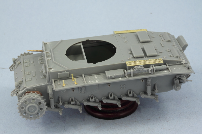
Today was another productive day with all major construction completed. Picking up right where I left off, I added the wiring conduit from the siren/indicator light down to the main headlight with 0.5mm diameter solder. This was carefully bent to shape and then glued in place with liquid glue. Once that had dried, I added small retaining brackets using the flexible bits on the Eduard frets that are the connection points for regular PE parts that were bent to a curved shape around a piece of solder with tweezers then glued into place with CA gel.

The remaining element from Step 14 was also dealt with by installing the mount for the antenna swivel arm to the hull side. The kit doesn't provide an antenna, so I clipped off the stub that was molded onto the swivel arm and drilled out a hole with a #72 finger drill and installed a Lion Marc 2m brass antenna with CA gel. To protect the antenna, this was only dry fit for the shot to be sure I had the alignment correct for the mount and will be permanently installed later.

The remaining steps deal with the turret and Step 15 assembles the top and bottom halves along with the hatch hinges and interior frames and turret front plate.

Step 16 adds the interior portion of the gun mount and hinge pin covers and can remain movable after installation if you don't apply glue to the hinge parts E30 and E31 where they mate up with the assembled E25 and E26. I also skipped ahead a bit to Step 20 since I am replacing the gun and mantlet entirely with the Armorscale barrel and resin mantlet. Adding it now is much easier than after all the details were installed and some small surgery was needed on the Armorscale resin mantlet to get it to fit. The back of the resin mantlet has mount points and guides that are designed to work with the newer DML Smart Kit and these all had to be cut down and sanded smooth to allow a proper fit to this older kit's mount parts. The mantlet was glued in place with CA gel and there's sufficient stiffness in the pins to support the weight of the gun so for now I haven't glued it down but will after painting to pose the gun at the desired angle.

Steps 16-18 deal with various details including the turret stowage bin. The bin assembles easily enough but the base is hollow so this needed to be blanked off using sheet styrene to avoid it being visible once mounted. Some putty work was also needed at the top portions to create the right seamless look.

The rest of the turret details were added as called for in the instructions and everything was going great right up until it came time to add the side hatches. The kit provides some nicely detailed doors and hinges and the doors fit very tightly together. While I was test fitting one side, the smaller half of the hatch pinged off into oblivion...I spent a full hour carefully searching the work bench, shelves, and floor but to no avail. This required a "Plan B" solution which involved removing the hinge points and using the one-piece hatches provided on sprue F and marked as not for use instead. The detail isn't as good but at least I still have hatches!
The turret lifting eyes were the only parts that required some modifications in these steps...the kit parts aren't really hooks as they are molded as solid knobs. I opened them up by drilling a hole in their centers with a #76 finger drill and the carefully creating the "hook" by cutting into the hole with the tips of my sprue cutters and then carefully removing the base to create the hook.

A test fit to the hull showed everything is playing nice together and the turret fits well into the ring opening provided. I had originally planned to fit a small canvas dust cover to the gun barrel but have decided against that as I don't want to cover up the nice detail provided by the Armorscale barrel. That means this one's ready for paint as the only other thing remaining is the track assembly and I can do that while the paint is curing.

The remaining element from Step 14 was also dealt with by installing the mount for the antenna swivel arm to the hull side. The kit doesn't provide an antenna, so I clipped off the stub that was molded onto the swivel arm and drilled out a hole with a #72 finger drill and installed a Lion Marc 2m brass antenna with CA gel. To protect the antenna, this was only dry fit for the shot to be sure I had the alignment correct for the mount and will be permanently installed later.
The remaining steps deal with the turret and Step 15 assembles the top and bottom halves along with the hatch hinges and interior frames and turret front plate.
Step 16 adds the interior portion of the gun mount and hinge pin covers and can remain movable after installation if you don't apply glue to the hinge parts E30 and E31 where they mate up with the assembled E25 and E26. I also skipped ahead a bit to Step 20 since I am replacing the gun and mantlet entirely with the Armorscale barrel and resin mantlet. Adding it now is much easier than after all the details were installed and some small surgery was needed on the Armorscale resin mantlet to get it to fit. The back of the resin mantlet has mount points and guides that are designed to work with the newer DML Smart Kit and these all had to be cut down and sanded smooth to allow a proper fit to this older kit's mount parts. The mantlet was glued in place with CA gel and there's sufficient stiffness in the pins to support the weight of the gun so for now I haven't glued it down but will after painting to pose the gun at the desired angle.
Steps 16-18 deal with various details including the turret stowage bin. The bin assembles easily enough but the base is hollow so this needed to be blanked off using sheet styrene to avoid it being visible once mounted. Some putty work was also needed at the top portions to create the right seamless look.
The rest of the turret details were added as called for in the instructions and everything was going great right up until it came time to add the side hatches. The kit provides some nicely detailed doors and hinges and the doors fit very tightly together. While I was test fitting one side, the smaller half of the hatch pinged off into oblivion...I spent a full hour carefully searching the work bench, shelves, and floor but to no avail. This required a "Plan B" solution which involved removing the hinge points and using the one-piece hatches provided on sprue F and marked as not for use instead. The detail isn't as good but at least I still have hatches!
The turret lifting eyes were the only parts that required some modifications in these steps...the kit parts aren't really hooks as they are molded as solid knobs. I opened them up by drilling a hole in their centers with a #76 finger drill and the carefully creating the "hook" by cutting into the hole with the tips of my sprue cutters and then carefully removing the base to create the hook.
A test fit to the hull showed everything is playing nice together and the turret fits well into the ring opening provided. I had originally planned to fit a small canvas dust cover to the gun barrel but have decided against that as I don't want to cover up the nice detail provided by the Armorscale barrel. That means this one's ready for paint as the only other thing remaining is the track assembly and I can do that while the paint is curing.
-
Bill Plunk
- Posts: 1245
- Joined: Wed Sep 28, 2022 10:18 pm
WIP 12-24-2009
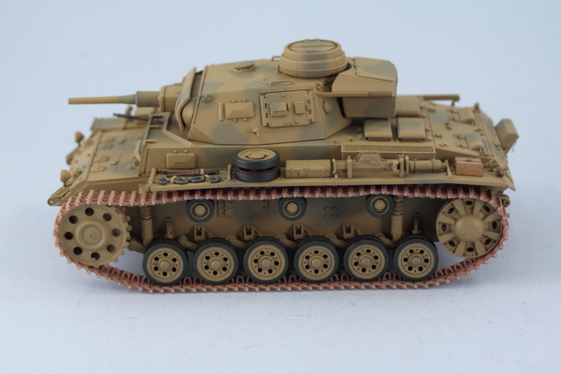
While we were spared the really severe weather here in El Paso that the rest of the plains/rockies got yesterday, it was still relatively cold here in the desert with the temps in the mid-to-high 40s. The wind wasn't very strong though, so that meant I was able to get some paint work done in the garage without freezing in the process.
I started in by applying a primer coat of Model Master enamel Italian Dark Brown. This allowed me to check all the putty work I'd done previously and also provides a nice underlying coat over the kit plastic to make sure I don't leave any bare spots along the way.

This was followed by the base coat of MM enamel Afrika Grunbraun '41, Testors' version of RAL 8000 as called for in the Tropen scheme authorized for the N. Afrika theater. I applied this in multiple mist coats to build it up over the primer coat.

Next came the camo pattern of 1/3 disruptive RAL 7008 in the form of MM enamel Afrika Khakibraun '41. This was applied as the light was fading and I can see there are a couple of thin spots that I need to work on, I'll take care of that tomorrow but the pattern is at least on.

I also worked on the road wheels, including the spares that will mount on the fender and at the "cow catcher" front with the spare track run to be added later. These were primed with the Italian Dark Brown then had the rubber rims air brushed with MM enamel Gunmetal. The inner hubs were air brushed with a custom-mix for the Red Oxide primer using a circle template while the outer hubs were air brushed with the RAL 8000 base coat color to match the hull, also via circle template.

I started in by applying a primer coat of Model Master enamel Italian Dark Brown. This allowed me to check all the putty work I'd done previously and also provides a nice underlying coat over the kit plastic to make sure I don't leave any bare spots along the way.
This was followed by the base coat of MM enamel Afrika Grunbraun '41, Testors' version of RAL 8000 as called for in the Tropen scheme authorized for the N. Afrika theater. I applied this in multiple mist coats to build it up over the primer coat.
Next came the camo pattern of 1/3 disruptive RAL 7008 in the form of MM enamel Afrika Khakibraun '41. This was applied as the light was fading and I can see there are a couple of thin spots that I need to work on, I'll take care of that tomorrow but the pattern is at least on.
I also worked on the road wheels, including the spares that will mount on the fender and at the "cow catcher" front with the spare track run to be added later. These were primed with the Italian Dark Brown then had the rubber rims air brushed with MM enamel Gunmetal. The inner hubs were air brushed with a custom-mix for the Red Oxide primer using a circle template while the outer hubs were air brushed with the RAL 8000 base coat color to match the hull, also via circle template.
-
Bill Plunk
- Posts: 1245
- Joined: Wed Sep 28, 2022 10:18 pm
WIP 12-27-2009
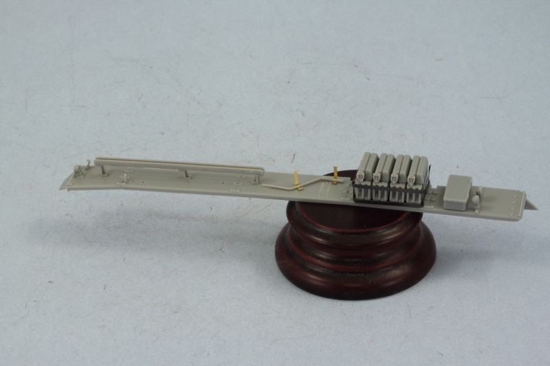
With the inevitable break in bench time that Christmas involves, I was able to get in some more progress today. The day's not over but the next round of work involves assembling the MK tracks so I figured I should go ahead and post what has been done and buckle down and get the tracks built!
First order of business was joining up the road wheel halves and then installing them to the hull. This was done using regular glue to allow for some adjustments where needed to get the wheels to sit level. The return rollers were also added. The hull was set off to the side and allowed to set up for a while to avoid disturbing the wheels.

I stayed busy by working on the fender gear details while the wheels set up. The pioneer tools had their metal portions painted with MM Metalizer non-buffing Gunmetal and lightly dry brushed with Steel while the wood portions were painted with a special "wood" mix that's a light tan color followed by a light wash of thinned Leather. Once the wash was dry, I added some additional color variation using artist pastel Burnt Umber applied with a square tip brush. The Bakelite handles on the wire cutters were painted with Italian Dark Brown and the rubber end caps with enamel Gunmetal. The tools were secured in place with the Griffon clamps and a small amount of liquid glue added to insure they didn't shift around any in the future. I added a clamp handle courtesy of the Griffon clamp set to the shovel clamp for a little more detail as well.
The extra road wheel on the left fender was also added and positioned carefully so as not to interfere with the turret rotation overhang. I also detailed and installed the jerry cans for the right fender. These were first airbrushed with Panzer Gray and the spouts were detailed the same was as the metal portions of the pioneer tools. I added the water can cross markings by hand to simulate the same way the crews did it with Light Gray and also added some scuffing and wear by lightly brushing some Steel along the edges and bases of the cans.
I also secured the gun elevation in a fixed position at this stage by applying some liquid glue on the inside of the turret to the hinge points. I held the barrel and mantlet in position until the glue "grabbed" enough to hold the weight and then let it set up.


The rear hull details also got some attention. I picked out the rear Notek lenses with Tamiya Clear Green and the brake light lenses with Clear Red. The mufflers were also detailed with a basecoat of non-buffing Metalizer Gunmetal followed by a wash of Rust and some dry brushed Burnt Umber. The smoke candle chains were detailed with the same Metalizer Gunmetal to round things out in this department.

Now it's off to watch some football and begin assembling the MK tracks!
First order of business was joining up the road wheel halves and then installing them to the hull. This was done using regular glue to allow for some adjustments where needed to get the wheels to sit level. The return rollers were also added. The hull was set off to the side and allowed to set up for a while to avoid disturbing the wheels.
I stayed busy by working on the fender gear details while the wheels set up. The pioneer tools had their metal portions painted with MM Metalizer non-buffing Gunmetal and lightly dry brushed with Steel while the wood portions were painted with a special "wood" mix that's a light tan color followed by a light wash of thinned Leather. Once the wash was dry, I added some additional color variation using artist pastel Burnt Umber applied with a square tip brush. The Bakelite handles on the wire cutters were painted with Italian Dark Brown and the rubber end caps with enamel Gunmetal. The tools were secured in place with the Griffon clamps and a small amount of liquid glue added to insure they didn't shift around any in the future. I added a clamp handle courtesy of the Griffon clamp set to the shovel clamp for a little more detail as well.
The extra road wheel on the left fender was also added and positioned carefully so as not to interfere with the turret rotation overhang. I also detailed and installed the jerry cans for the right fender. These were first airbrushed with Panzer Gray and the spouts were detailed the same was as the metal portions of the pioneer tools. I added the water can cross markings by hand to simulate the same way the crews did it with Light Gray and also added some scuffing and wear by lightly brushing some Steel along the edges and bases of the cans.
I also secured the gun elevation in a fixed position at this stage by applying some liquid glue on the inside of the turret to the hinge points. I held the barrel and mantlet in position until the glue "grabbed" enough to hold the weight and then let it set up.
The rear hull details also got some attention. I picked out the rear Notek lenses with Tamiya Clear Green and the brake light lenses with Clear Red. The mufflers were also detailed with a basecoat of non-buffing Metalizer Gunmetal followed by a wash of Rust and some dry brushed Burnt Umber. The smoke candle chains were detailed with the same Metalizer Gunmetal to round things out in this department.
Now it's off to watch some football and begin assembling the MK tracks!
-
Bill Plunk
- Posts: 1245
- Joined: Wed Sep 28, 2022 10:18 pm
WIP 12-31-2009
One of the downsides to being home on vacation this week was the need to take care of various non-model related things as well...which limited somewhat my time at the bench but just in time for the end of the year, I was able to make some good progress.
The tracks were the last major item needing attention and I duly set to work assembling the MK workable tracks. The MK set includes a jig that holds 9 links at a time and the pins are provided on separate handles with the pins handed inside vs. outside. Adding the pins is straightforward, just a touch of glue needed at the head, insert to join the links, then twist off the handle and voila! workable tracks. The hollow guide horns are provided as separate parts and these also have a handle. Once the horns are glued in place and the glue had set up after a few minutes, the handles were easily removed with sprue cutters and the top lightly sanded where needed.

The MK instructions recommend that 92-95 links are needed for a Pz III vehicle but I always take those recommendations with a grain of salt and test fit to be sure the count is right. I assembled two runs of 90 links each to get me in range.

The idler was dry fit onto the mount and the mount itself needed to be trimmed down a couple of mm to allow the idler to seat properly. The MK runs were test fit on either side and two more links added to get to 92 per side with the amount of sag I wanted.
The MK SK-26 set doesn't provide very many extra links but since I had used one of these sets before, I had some additional links available and used these to create the added armor runs for the superstructure front plate. I used the kit supplied links for the "cow catcher" run between the tow points that also holds the two extra road wheels. The kit links required a lot of clean up in terms of flash, ejector marks on the faces, etc. and I ended up using 16 links to get the right curve and angle needed. The tow pins are removable so that I can paint and detail the run separately and were used to help hold and shape the curve along with the spares while the glue set up.

Tomorrow, weather permitting, I should get the tracks painted and installed and then it's on to the decals!
The tracks were the last major item needing attention and I duly set to work assembling the MK workable tracks. The MK set includes a jig that holds 9 links at a time and the pins are provided on separate handles with the pins handed inside vs. outside. Adding the pins is straightforward, just a touch of glue needed at the head, insert to join the links, then twist off the handle and voila! workable tracks. The hollow guide horns are provided as separate parts and these also have a handle. Once the horns are glued in place and the glue had set up after a few minutes, the handles were easily removed with sprue cutters and the top lightly sanded where needed.
The MK instructions recommend that 92-95 links are needed for a Pz III vehicle but I always take those recommendations with a grain of salt and test fit to be sure the count is right. I assembled two runs of 90 links each to get me in range.
The idler was dry fit onto the mount and the mount itself needed to be trimmed down a couple of mm to allow the idler to seat properly. The MK runs were test fit on either side and two more links added to get to 92 per side with the amount of sag I wanted.
The MK SK-26 set doesn't provide very many extra links but since I had used one of these sets before, I had some additional links available and used these to create the added armor runs for the superstructure front plate. I used the kit supplied links for the "cow catcher" run between the tow points that also holds the two extra road wheels. The kit links required a lot of clean up in terms of flash, ejector marks on the faces, etc. and I ended up using 16 links to get the right curve and angle needed. The tow pins are removable so that I can paint and detail the run separately and were used to help hold and shape the curve along with the spares while the glue set up.
Tomorrow, weather permitting, I should get the tracks painted and installed and then it's on to the decals!