Dragon Pzkpfw IV Ausf. C (2012)
-
Bill Plunk
- Posts: 1245
- Joined: Wed Sep 28, 2022 10:18 pm
Dragon Pzkpfw IV Ausf. C (2012)
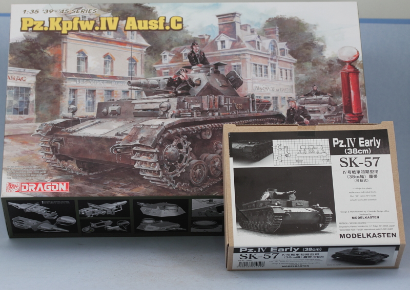
Build log for Dragon kit #6291 Pzkpfw IV Ausf C "Super Kit" with Model Kasten SK-57 workable tracks.
-
Bill Plunk
- Posts: 1245
- Joined: Wed Sep 28, 2022 10:18 pm
WIP 09-23-2011
The DML "Super Kit" line of early-war Pz IVs boast a parts count of over 1000 parts and that means that even simple things involve a lot of parts and assembly. Work began in Step 1 with the assembly of the sprockets, idlers, road wheels, and return rollers. I opted for the simpler 7-part sprocket assembly instead of the 31-part (24 separate tiny bolts) and used the PE options for the idlers.
The road wheels are provided with the rubber rims separate and have a tight friction fit, so they are dry-fit for now and will be used to mask the hubs later on when I get to the painting stage. Having built the IV-E kit some time back that utilized this same design, I know that it's important not to get any paint on the hubs as that added fractional mm to the diameter can cause the rubber rims to not fit or even split if forced on. Each of the rims had their molding seam removed with a sanding stick before being dry-fit. The hubs each have 2 sprue attachment points that have to be carefully cleaned up to avoid damaging the delicate rims.
Total parts count to get to this stage: 118

Step 1 is still not finished, next up will be the suspension bogeys (8) which are another multi-part assembly (8 parts each).
The road wheels are provided with the rubber rims separate and have a tight friction fit, so they are dry-fit for now and will be used to mask the hubs later on when I get to the painting stage. Having built the IV-E kit some time back that utilized this same design, I know that it's important not to get any paint on the hubs as that added fractional mm to the diameter can cause the rubber rims to not fit or even split if forced on. Each of the rims had their molding seam removed with a sanding stick before being dry-fit. The hubs each have 2 sprue attachment points that have to be carefully cleaned up to avoid damaging the delicate rims.
Total parts count to get to this stage: 118
Step 1 is still not finished, next up will be the suspension bogeys (8) which are another multi-part assembly (8 parts each).
-
Bill Plunk
- Posts: 1245
- Joined: Wed Sep 28, 2022 10:18 pm
WIP 09-29-2011
More progress to report...finally got through Step 1 (well mostly). I completed the suspension elements which was kind of a slog as there are 56 parts involved in their assembly. It pays off though as the elements remain workable if you're strategic in your assembly and careful as to where you do and don't apply glue. The instruction steps don't provide any "no glue here" type of guidance, so you have to figure it out on your own. The key is to only glue the top part of the cap (parts A10/A28) while still trapping the suspension arms effectively. I assembled one hull side at a time in order to avoid any parts confusion as it's very easy to get turned around if you aren't careful in the process because there are so many parts involved. I deliberately didn't fill the ejector mark visible under one of the wheel mount pins because it will be hidden away once the wheels are installed.

The rest of Step 1 deals with attaching all the details to the rear hull plate but I will deal with that a bit later as it's easier to install the plate into the hull first and then add the details to avoid potential loss/damage to stuff in the process.
Step 2 starts work on the hull itself. The nose plates are added and I went ahead and also added the rear hull plates at the same time even though they aren't called for in the instructions until Step 4. Other small details are added in this step including the fuel tank spouts, the external fuel access doors, the base of the turret basket, and the rubber bump stops.
Step 3 is a detail step and deals with the final drive housings. The armored covers are provided as a single piece but with 6 separate small bolts that need to be added to each cover. Small locater bumps are provided to aid in their placement. I carefully removed them from the sprues with a pair of tweezer cutters and then used a toothpick moistened with some spit to pick up the bolt and place it in a small amount of liquid glue on the locater bump. Rinse and repeat for each bolt with a touch of glue once in place to insure it stayed put and voil�! the step was done.

Now it's on to installing the actual suspension elements and circling back to take care of the rear hull plates as the next adventure.
The rest of Step 1 deals with attaching all the details to the rear hull plate but I will deal with that a bit later as it's easier to install the plate into the hull first and then add the details to avoid potential loss/damage to stuff in the process.
Step 2 starts work on the hull itself. The nose plates are added and I went ahead and also added the rear hull plates at the same time even though they aren't called for in the instructions until Step 4. Other small details are added in this step including the fuel tank spouts, the external fuel access doors, the base of the turret basket, and the rubber bump stops.
Step 3 is a detail step and deals with the final drive housings. The armored covers are provided as a single piece but with 6 separate small bolts that need to be added to each cover. Small locater bumps are provided to aid in their placement. I carefully removed them from the sprues with a pair of tweezer cutters and then used a toothpick moistened with some spit to pick up the bolt and place it in a small amount of liquid glue on the locater bump. Rinse and repeat for each bolt with a touch of glue once in place to insure it stayed put and voil�! the step was done.
Now it's on to installing the actual suspension elements and circling back to take care of the rear hull plates as the next adventure.
-
Bill Plunk
- Posts: 1245
- Joined: Wed Sep 28, 2022 10:18 pm
WIP 10-01-2011
Work continued on the Step 4 elements with the installation of the suspension to the lower hull. I had deliberately left off parts A25/26 from the Step 1 assembly and it's a good thing...they are a very tight fit into their positions on the lower hull, virtually a snap fit, and that would've been much harder to get right if they were already glued to the suspension parts vs. being installed separately. I also had to shave down the front suspension bump (you can see in the pic below the difference between it and the rear one) in order for the first suspension element to sit correctly and not have the 2nd road wheel "float". The rear bump was fine as-is, no corrections required.

The rest of Step 4 deals with installing the armored extensions for the suspension on the hull bottom. 5 pieces per side and you have to be careful to get their alignment just right but otherwise no problems.

Then I cycled back to the rear hull details that had been called out in Step 1. I added those along with the rear hull-side tow hooks. There are two small locater holes that aren't used on this particular model that were filled with putty. The instructions never provide any indication this is needed but careful study of the later assembly steps shows nothing installs in those locations. I left off the kit-supplied PE chains for the engine crank cap and the tow pintle bar and will install those later as they are somewhat delicate and I don't want them getting lost or damaged at this stage.

Next up will begin working on the upper hull stuff.
The rest of Step 4 deals with installing the armored extensions for the suspension on the hull bottom. 5 pieces per side and you have to be careful to get their alignment just right but otherwise no problems.
Then I cycled back to the rear hull details that had been called out in Step 1. I added those along with the rear hull-side tow hooks. There are two small locater holes that aren't used on this particular model that were filled with putty. The instructions never provide any indication this is needed but careful study of the later assembly steps shows nothing installs in those locations. I left off the kit-supplied PE chains for the engine crank cap and the tow pintle bar and will install those later as they are somewhat delicate and I don't want them getting lost or damaged at this stage.
Next up will begin working on the upper hull stuff.
-
Bill Plunk
- Posts: 1245
- Joined: Wed Sep 28, 2022 10:18 pm
WIP 10-04-2011
Moving right along with this one, I started work on the upper hull with Step 5. This step deals with the air intakes and the upper hull rear plate. The option is provided to use either a one-piece styrene assembly for the intakes or use a 7-part PE assembly. I opted for the PE as the intakes on the C are a prominent feature and the PE provides a more in-scale appearance. The PE assembly was done using CA gel as the DML design is pretty sturdy on its own as it employs a slot/tab arrangement for each of the parts.

The intakes were glued into place with CA gel at the front only and then the rear hull plate fitted. This was to insure that I had a solid alignment and some flexibility at the rear portions of the intakes to make minor fit adjustments if needed. Once the rear plate had set, I went back and used liquid glue and some strategic amounts of CA gel to get the rest of the intakes aligned. The pic below is pre-alignment.
I also left off part E23 until the upper and lower hulls are joined as it is the top half of the bolt flange on the real deal and needs to align with the lower hull to be correct. The hooks for the tow cable were also left off for the time being to avoid damage/loss and will be added later.

Step 6 assembles the superstructure front plate and includes some nice optional detail for the driver's periscope and vision block as well as the radio operator's pistol port and vision block. None of this will be seen on my build since those hatches will remain closed, so the assembly of those parts was skipped. I did complete the exterior as called for with the installation of the pistol port, vision port cover, and the driver's visors and rain shield. I posed the driver's visors in the open position.
Step 7 is a minor detail step that assembles the jack block (skipped for now) and the hull vision ports (skipped entirely). Step 8 assembles the upper hull superstructure and this requires some strategic thinking in terms of order. I started with the side panels first, using regular glue as they attach only at the top edge and let that set a bit. Then I added the front plate again using regular glue and careful use of liquid glue where it met the side panels. Once that had set enough to handle without causing things to shift, I used finger pressure and light doses of liquid glue along the top edges to get the plate edges to merge with the molded-on weld detail.
While all that was drying, I assembled the glacis plate along with the transmission and brake access hatches. These were all in the closed position since I don't have any interior to show off but have nice interior detail as well...the only drawback is that the transmission access plate fits a little loose in its position so careful alignment is called for to avoid one side having a larger gap than the other. I did not join the glacis to the superstructure as called for just yet...I will wait to do that until I'm ready to join the upper and lower hulls together to avoid any possible fit issues.
Rounding things out in the step, I installed the engine deck hatches, all in the closed position. The kit provides detail parts for the intake fans but those aren't needed unless that hatch is being displayed open, so they will end up in the spares bin.

Next up will be the fenders and the joining of the upper and lower hull together.
The intakes were glued into place with CA gel at the front only and then the rear hull plate fitted. This was to insure that I had a solid alignment and some flexibility at the rear portions of the intakes to make minor fit adjustments if needed. Once the rear plate had set, I went back and used liquid glue and some strategic amounts of CA gel to get the rest of the intakes aligned. The pic below is pre-alignment.
I also left off part E23 until the upper and lower hulls are joined as it is the top half of the bolt flange on the real deal and needs to align with the lower hull to be correct. The hooks for the tow cable were also left off for the time being to avoid damage/loss and will be added later.
Step 6 assembles the superstructure front plate and includes some nice optional detail for the driver's periscope and vision block as well as the radio operator's pistol port and vision block. None of this will be seen on my build since those hatches will remain closed, so the assembly of those parts was skipped. I did complete the exterior as called for with the installation of the pistol port, vision port cover, and the driver's visors and rain shield. I posed the driver's visors in the open position.
Step 7 is a minor detail step that assembles the jack block (skipped for now) and the hull vision ports (skipped entirely). Step 8 assembles the upper hull superstructure and this requires some strategic thinking in terms of order. I started with the side panels first, using regular glue as they attach only at the top edge and let that set a bit. Then I added the front plate again using regular glue and careful use of liquid glue where it met the side panels. Once that had set enough to handle without causing things to shift, I used finger pressure and light doses of liquid glue along the top edges to get the plate edges to merge with the molded-on weld detail.
While all that was drying, I assembled the glacis plate along with the transmission and brake access hatches. These were all in the closed position since I don't have any interior to show off but have nice interior detail as well...the only drawback is that the transmission access plate fits a little loose in its position so careful alignment is called for to avoid one side having a larger gap than the other. I did not join the glacis to the superstructure as called for just yet...I will wait to do that until I'm ready to join the upper and lower hulls together to avoid any possible fit issues.
Rounding things out in the step, I installed the engine deck hatches, all in the closed position. The kit provides detail parts for the intake fans but those aren't needed unless that hatch is being displayed open, so they will end up in the spares bin.
Next up will be the fenders and the joining of the upper and lower hull together.
-
Bill Plunk
- Posts: 1245
- Joined: Wed Sep 28, 2022 10:18 pm
WIP 10-05-2011
Today's efforts focused on the fenders and joining the upper and lower hull together. That meant a departure from the kit instruction assembly order as that isn't called for until Step 20 as the next to last item but involves a great deal of peril if you follow that path. Why do you ask? Because the attachment points between the fenders and the upper and lower halves have to be in perfect alignment for everything to work correctly and aside from the tread plate pattern on the fenders, there's nothing to guide you in attaching the fenders directly to the upper hull as the instructions call for.
Instead of doing that, I chose to attach the fenders and glacis plate (remember the instructions wanted you to attach that to the upper hull too in the previous Step 8) directly to the lower hull. Two choices of fenders are provided, those on the D sprue have open locater holes while those on the S sprue are smooth and meant to be used with the kit-supplied "clean" tools and PE clamps. I opted for the S fenders and removed the bolts on the rear (the instructions indicate this is needed only on the D fenders but is essential regardless of which set is used) that aren't accurate for the Ausf C. I also used a pin vise and drill bit to open up the necessary holes on the front of the fenders to take the headlights later on. No hole is provided for the driver's side siren mount so when it is installed, I will use the headlight position as a guide.
The fenders have a tendency to want to droop due to their weight and the narrow attachment surfaces available for gluing, so it's essential to install one fender side at a time and use finger pressure and eyeball checks to make sure they install as level as possible.

After the fenders were set, I installed the upper hull. A combination of liquid and regular glue was used and gentle finger pressure under the fenders to insure a solid join all around was achieved. Rubber bands would've been counter-productive here in terms of causing the fenders to bow, so time and patience were required working one side at a time until the glue had set up enough to let it sit on its own.

There was a gap at the hull rear that I couldn't find either a cause or remedy for other than to just fill it. The gap was too wide for putty, so I opted for some thin styrene rod I had on hand. Generous amounts of liquid glue were applied and pressure with a toothpick to wedge it into the gap and once the glue had dried, I used a square tip needle file to sand it down.

That left the rest of Step 9 to complete in the form of the front and rear fenders as well as the driver and radio operator hatches.

Next up will be fitting all the PE clamps to the fenders for the various gear that has to go there.
Instead of doing that, I chose to attach the fenders and glacis plate (remember the instructions wanted you to attach that to the upper hull too in the previous Step 8) directly to the lower hull. Two choices of fenders are provided, those on the D sprue have open locater holes while those on the S sprue are smooth and meant to be used with the kit-supplied "clean" tools and PE clamps. I opted for the S fenders and removed the bolts on the rear (the instructions indicate this is needed only on the D fenders but is essential regardless of which set is used) that aren't accurate for the Ausf C. I also used a pin vise and drill bit to open up the necessary holes on the front of the fenders to take the headlights later on. No hole is provided for the driver's side siren mount so when it is installed, I will use the headlight position as a guide.
The fenders have a tendency to want to droop due to their weight and the narrow attachment surfaces available for gluing, so it's essential to install one fender side at a time and use finger pressure and eyeball checks to make sure they install as level as possible.
After the fenders were set, I installed the upper hull. A combination of liquid and regular glue was used and gentle finger pressure under the fenders to insure a solid join all around was achieved. Rubber bands would've been counter-productive here in terms of causing the fenders to bow, so time and patience were required working one side at a time until the glue had set up enough to let it sit on its own.
There was a gap at the hull rear that I couldn't find either a cause or remedy for other than to just fill it. The gap was too wide for putty, so I opted for some thin styrene rod I had on hand. Generous amounts of liquid glue were applied and pressure with a toothpick to wedge it into the gap and once the glue had dried, I used a square tip needle file to sand it down.
That left the rest of Step 9 to complete in the form of the front and rear fenders as well as the driver and radio operator hatches.
Next up will be fitting all the PE clamps to the fenders for the various gear that has to go there.
-
Bill Plunk
- Posts: 1245
- Joined: Wed Sep 28, 2022 10:18 pm
WIP 10-14-2011
I've had to take care of some odds and ends and begin getting ready for my MBA classes which start on the 27th, so progress has slowed a bit on the build.
Before I tackle the fender clamps, I decided to go ahead and address the rear hull details. The instructions put this off to the very last step but there's no reason to wait that long. The main muffler assembles from 6 parts and they all fit together fine except for part D17 to J4. I had to carefully trim the inside of D17 and use a round needle file to sand it down a bit to get it to fit correctly. I also used a micro drill bit to deepen the exhaust mouth a bit more before adding it. The auxiliary exhaust for the turret traverse motor is another 4 part assembly but it's best if you don't add part W32 until you're ready to install it to the hull.
Speaking of installations, I had originally thought to leave the exhausts separate and install after painting but test fits discovered that would have been a bad idea. Possibly due to the gap issue with the upper hull join from earlier, it was necessary for me to carefully sand down the bolt strip edge and the curved support trays before the main exhaust would fit properly. This also made for a tight fit for the curved connection pipe on the auxiliary exhaust (W32) and some careful sanding/trimming was needed on it too to get everything to play nice.
I also added the other details from previous steps such as the brake light from Step 1, the pre-formed metal tow cable hooks from Step 5, and the PE reflector from Step 10. After checking reference photos, I went ahead and also installed the rear smoke candle rack over the exhaust. This is an 11 part assembly with small PE dividers provided and individual grenades, so a lot happening in a small space. I left off the PE pull chains for now and will add those later.

Now I can tackle the fender stuff before moving on to the turret!
Before I tackle the fender clamps, I decided to go ahead and address the rear hull details. The instructions put this off to the very last step but there's no reason to wait that long. The main muffler assembles from 6 parts and they all fit together fine except for part D17 to J4. I had to carefully trim the inside of D17 and use a round needle file to sand it down a bit to get it to fit correctly. I also used a micro drill bit to deepen the exhaust mouth a bit more before adding it. The auxiliary exhaust for the turret traverse motor is another 4 part assembly but it's best if you don't add part W32 until you're ready to install it to the hull.
Speaking of installations, I had originally thought to leave the exhausts separate and install after painting but test fits discovered that would have been a bad idea. Possibly due to the gap issue with the upper hull join from earlier, it was necessary for me to carefully sand down the bolt strip edge and the curved support trays before the main exhaust would fit properly. This also made for a tight fit for the curved connection pipe on the auxiliary exhaust (W32) and some careful sanding/trimming was needed on it too to get everything to play nice.
I also added the other details from previous steps such as the brake light from Step 1, the pre-formed metal tow cable hooks from Step 5, and the PE reflector from Step 10. After checking reference photos, I went ahead and also installed the rear smoke candle rack over the exhaust. This is an 11 part assembly with small PE dividers provided and individual grenades, so a lot happening in a small space. I left off the PE pull chains for now and will add those later.
Now I can tackle the fender stuff before moving on to the turret!
-
Bill Plunk
- Posts: 1245
- Joined: Wed Sep 28, 2022 10:18 pm
WIP 10-15-2011
Work continued on the hull...since last time I addressed the rear hull it was only fitting that I also take care of the front hull. In Step 20 the instructions call for the assembly and installation of the front tow points so those were added. Their assembly is a little tricky as the parts for the right and left points are all numbered the same but need to be assembled differently to insure the correct toed-in angle on both sides. The key here is the base, part D7, and how it's d-shaped locater pin is aligned on the back. I had to shave down slightly the actual tow pins in order for them to fit properly as well. The PE retaining chains will be added later just before painting.
I also added the front headlights to both fenders along with the siren. The kit parts have a molded on cable conduit but it's too short and doesn't reach all the way to the hull glacis like it should. The same is true of the alternative kit-supplied pre-bent steel wire...so I used a #76 finger drill and 0.5mm solder to provide the conduits instead.

I returned to Step 10 and started work on the fender details and clamps. The instructions provide an exact replica line-diagram to aid in the placement of the tools on the "clean" fender that I opted for vs. using the one with locater holes. The space tolerances are a bit tight so it required a lot of double and triple checking before committing. Only the bases of the clamps were installed, the retaining clasps will be added after the tools have been painted and detailed later on. I also used Griffon PE clamps (2 part) instead of the DML 3-part clamps for the two crow bars. I used Gator Grip glue vs CA to allow for more flexibility and work-time to insure the clamps were all positioned just right. I left off the end-cap PE parts for the wire-cutters and crow-bars as they attach directly to the tools themselves vs. gluing to the fender but will add those later on.
The toughest part of this area bar none was the crew step. The kit only supplies parts in PE for this so there's no alternative and it is a devilishly tricky/complex assembly of multiple parts (8 PE, 1 styrene). This is complicated by the fact that the PE "legs" of the step have round holes to match up with the styrene step bar but the holes aren't the same diameter...so some very careful attention with a round needle file was needed to correct that. I also replaced the kit part for the track-spreader tool with a thinner more in-scale piece of styrene rod.

Next up will be the other fender side.
I also added the front headlights to both fenders along with the siren. The kit parts have a molded on cable conduit but it's too short and doesn't reach all the way to the hull glacis like it should. The same is true of the alternative kit-supplied pre-bent steel wire...so I used a #76 finger drill and 0.5mm solder to provide the conduits instead.
I returned to Step 10 and started work on the fender details and clamps. The instructions provide an exact replica line-diagram to aid in the placement of the tools on the "clean" fender that I opted for vs. using the one with locater holes. The space tolerances are a bit tight so it required a lot of double and triple checking before committing. Only the bases of the clamps were installed, the retaining clasps will be added after the tools have been painted and detailed later on. I also used Griffon PE clamps (2 part) instead of the DML 3-part clamps for the two crow bars. I used Gator Grip glue vs CA to allow for more flexibility and work-time to insure the clamps were all positioned just right. I left off the end-cap PE parts for the wire-cutters and crow-bars as they attach directly to the tools themselves vs. gluing to the fender but will add those later on.
The toughest part of this area bar none was the crew step. The kit only supplies parts in PE for this so there's no alternative and it is a devilishly tricky/complex assembly of multiple parts (8 PE, 1 styrene). This is complicated by the fact that the PE "legs" of the step have round holes to match up with the styrene step bar but the holes aren't the same diameter...so some very careful attention with a round needle file was needed to correct that. I also replaced the kit part for the track-spreader tool with a thinner more in-scale piece of styrene rod.
Next up will be the other fender side.
-
Bill Plunk
- Posts: 1245
- Joined: Wed Sep 28, 2022 10:18 pm
WIP 10-18-2011
I will confess to underestimating the amount of time required to complete all the PE work for the fender details called out in Step 11 so it took me longer to get this one done than the opposite side. Part of that was due to the fact that several of the parts had to be modified or adjusted for the PE to work and part of that was just the number of tools/parts involved and everything that had to be installed.
I originally had planned to install the holders for the spare tracks as separate pieces but I quickly abandoned that idea after realizing that trying to get all 8 of them perfectly aligned would be nearly impossible to achieve. I selected 4 of the "Magic" links (short guide horn variety) and cleaned them up, removing the two ejector marks on either side of the horn and removing slight flash inside the horn itself. I used a #76 pin vise to drill out the front ends to simulate the openings for the track pins and added the pins themselves to the rear end using small lengths of styrene rod glued in place with liquid glue. The PE holders were added and some care is needed when bending the complex "Z" shape, so the lighted magnifier got a work out along with some gymnastics with needle nosed pliers, finger nails, and tweezers!

I installed the antenna rest tray to the hull side and elected to pose the antenna in the down/stowed position since the inside of the tray had visible ejector marks that were hidden by the antenna and would have been a major pain to deal with otherwise. I held off adding the base, W15, that installs to the fender as I wanted to get the tool layout right first before committing to that.
Repeating the process used on the other fender in terms of the included-diagram template, I started at the rear of the fender and worked my way forward installing the clamps as needed. The idler tensioning wrenches had to be shaved down slightly to fit properly in their holders. I also had to grind down the small lip protrusion on the pre-formed brass shovel bracket on order for it to fit correctly in the space available. I used Griffon tool clamps for the crank starter (the instructions say to install 2 but only 1 was used on the C), the shovel, and the axe. The PE retaining clamp for the axe blade fell apart during the bending process so I used the Plan B axe and removed its molded on tool clamps as a stand-in.
I then went back and installed W15 to complete the step, removing the locater pin from the base and using liquid glue to get it solid to the fender. Once set, I used a pair of locking tweezers to gently lift the end of the antenna tray until it sat level with the tops of the base, applied some liquid glue and held it until it set to round things out.

I originally had planned to install the holders for the spare tracks as separate pieces but I quickly abandoned that idea after realizing that trying to get all 8 of them perfectly aligned would be nearly impossible to achieve. I selected 4 of the "Magic" links (short guide horn variety) and cleaned them up, removing the two ejector marks on either side of the horn and removing slight flash inside the horn itself. I used a #76 pin vise to drill out the front ends to simulate the openings for the track pins and added the pins themselves to the rear end using small lengths of styrene rod glued in place with liquid glue. The PE holders were added and some care is needed when bending the complex "Z" shape, so the lighted magnifier got a work out along with some gymnastics with needle nosed pliers, finger nails, and tweezers!
I installed the antenna rest tray to the hull side and elected to pose the antenna in the down/stowed position since the inside of the tray had visible ejector marks that were hidden by the antenna and would have been a major pain to deal with otherwise. I held off adding the base, W15, that installs to the fender as I wanted to get the tool layout right first before committing to that.
Repeating the process used on the other fender in terms of the included-diagram template, I started at the rear of the fender and worked my way forward installing the clamps as needed. The idler tensioning wrenches had to be shaved down slightly to fit properly in their holders. I also had to grind down the small lip protrusion on the pre-formed brass shovel bracket on order for it to fit correctly in the space available. I used Griffon tool clamps for the crank starter (the instructions say to install 2 but only 1 was used on the C), the shovel, and the axe. The PE retaining clamp for the axe blade fell apart during the bending process so I used the Plan B axe and removed its molded on tool clamps as a stand-in.
I then went back and installed W15 to complete the step, removing the locater pin from the base and using liquid glue to get it solid to the fender. Once set, I used a pair of locking tweezers to gently lift the end of the antenna tray until it sat level with the tops of the base, applied some liquid glue and held it until it set to round things out.
-
Bill Plunk
- Posts: 1245
- Joined: Wed Sep 28, 2022 10:18 pm
WIP 10-19-2011
Made some additional progress today. There were some small details left over from Step 11 that I needed to add. The instructions kind of sneak by the two small lifting hooks on the rear hull area as they show them, parts W34, as already installed and also incorrectly only show one installed on the right side (you need two and the kit includes both). Those were added along with the tiny PE slide covers for the keyholes on the engine access hatches and the brake access hatches. I also went ahead and added the retaining "dog chain" PE parts for the rear tow pin and the front hull tow pins.

That led me onward to Step 12 which begins work on the turret and deals exclusively with the commander's cupola. Options are provided to pose the shutters either open or closed and I decided on open. I will also pose the hatches in the open position as the interior detail provided in the kit parts is too good to not show. I'm also planning to have one of the turret side hatches open so this should provide a good compliment to that as well.
I left out the clear vision block parts for now as the way the cupola assembles makes it very easy to slip them in later provided I leave the cupola in two parts. That should make it easy to paint both the interior and exterior portions without having to mask any of the clear parts in the process.
It's worth noting at this stage that the instruction diagram showing the open vs closed shutter option incorrectly refers to parts Q2 when in fact they really mean parts Q5.

Next up is the turret base and work on the main gun.
That led me onward to Step 12 which begins work on the turret and deals exclusively with the commander's cupola. Options are provided to pose the shutters either open or closed and I decided on open. I will also pose the hatches in the open position as the interior detail provided in the kit parts is too good to not show. I'm also planning to have one of the turret side hatches open so this should provide a good compliment to that as well.
I left out the clear vision block parts for now as the way the cupola assembles makes it very easy to slip them in later provided I leave the cupola in two parts. That should make it easy to paint both the interior and exterior portions without having to mask any of the clear parts in the process.
It's worth noting at this stage that the instruction diagram showing the open vs closed shutter option incorrectly refers to parts Q2 when in fact they really mean parts Q5.
Next up is the turret base and work on the main gun.