Dragon T-34/76 German Army Beutepanzer (2012)
-
Bill Plunk
- Posts: 1245
- Joined: Wed Sep 28, 2022 10:18 pm
Dragon T-34/76 German Army Beutepanzer (2012)
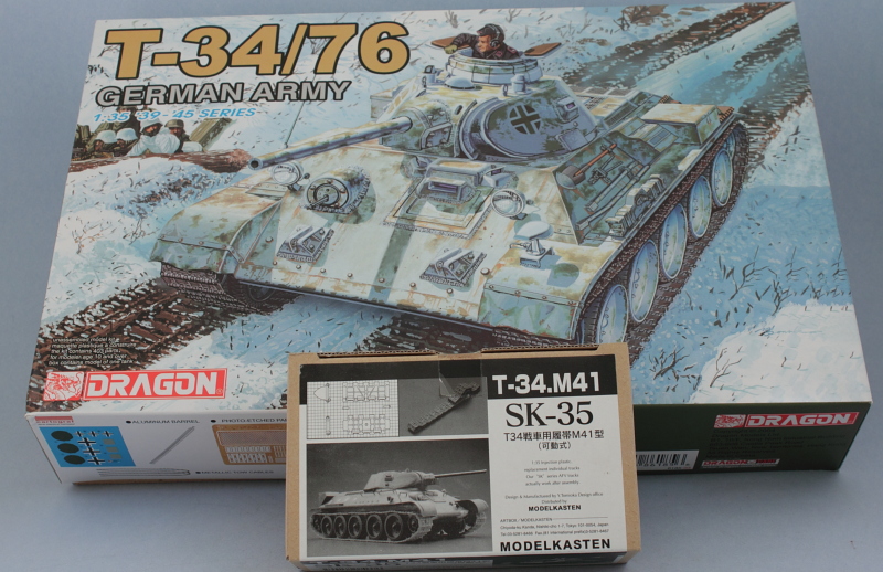
Build Log for Dragon kit #6185 T-34/76 German Army with Modelkasten SK-35 workable tracks.
-
Bill Plunk
- Posts: 1245
- Joined: Wed Sep 28, 2022 10:18 pm
WIP 10-21-2012
After carrying out the usual bench-clearing and cleaning ritual when a previous project is finished, the next victim was selected out of the stash and work began. This particular project is going to be relatively straightforward and I chose it mainly because I want to do some experimenting with white wash techniques and a Beute T-34 provides the perfect opportunity for it...that and the fact that it's coming up on winter by the calendar so timing also matches.
This kit has the photographic instructions that show the actual model already painted and build in different stages so it's essential to pay extra attention to the steps as parts tend to magically appear in position and can be missed if not careful. I started with Step 1 which calls for the assembly of the road wheels, drive wheels, and tensioning idlers. Each of these parts has multiple nodes and sprue connection points as well as mold seams present so there was substantial cleanup work involved in terms of careful trimming and sanding before they were all done.

Step 2 begins work on the lower hull and installs the suspension towers as well as a couple of parts for the drive housings. It's important that these all sit at the right height and are level with each other since the suspension swing arms install into them in the next step.

Step 3 adds the swing arms to both sides and also installs the idler arms and the bases for the drive wheels. The MK set includes some adapters that allow the drive wheels to remain rotatable so I added those first before installing the bases and wheels into position. The MK set also includes little shims that are added to the idler arms to provide some tension so they will stay in place unaided and allow the idler wheels to be adjusted for track sag later on. This is a nice touch and the shims were just a shade too tight so I carefully sanded them down after they were glued to the arm mounts until I could move the arms without too much force while still having enough friction to remain in place and hold their position.


That brought me to Step 4 which adds the hull underside details and the rear hull curved plate. As is common with DML instructions, there's an error in the tow point parts, they are reversed in terms of the part numbers and the sides they install to. Some finger pressure was needed to close up small gaps with the drive mounts but nothing major.

Steps 5 and 6 call for the installation of the wheels and tracks and that of course will come much later so they were skipped for now. Up next will begin work on the upper hull.
This kit has the photographic instructions that show the actual model already painted and build in different stages so it's essential to pay extra attention to the steps as parts tend to magically appear in position and can be missed if not careful. I started with Step 1 which calls for the assembly of the road wheels, drive wheels, and tensioning idlers. Each of these parts has multiple nodes and sprue connection points as well as mold seams present so there was substantial cleanup work involved in terms of careful trimming and sanding before they were all done.
Step 2 begins work on the lower hull and installs the suspension towers as well as a couple of parts for the drive housings. It's important that these all sit at the right height and are level with each other since the suspension swing arms install into them in the next step.
Step 3 adds the swing arms to both sides and also installs the idler arms and the bases for the drive wheels. The MK set includes some adapters that allow the drive wheels to remain rotatable so I added those first before installing the bases and wheels into position. The MK set also includes little shims that are added to the idler arms to provide some tension so they will stay in place unaided and allow the idler wheels to be adjusted for track sag later on. This is a nice touch and the shims were just a shade too tight so I carefully sanded them down after they were glued to the arm mounts until I could move the arms without too much force while still having enough friction to remain in place and hold their position.
That brought me to Step 4 which adds the hull underside details and the rear hull curved plate. As is common with DML instructions, there's an error in the tow point parts, they are reversed in terms of the part numbers and the sides they install to. Some finger pressure was needed to close up small gaps with the drive mounts but nothing major.
Steps 5 and 6 call for the installation of the wheels and tracks and that of course will come much later so they were skipped for now. Up next will begin work on the upper hull.
-
Bill Plunk
- Posts: 1245
- Joined: Wed Sep 28, 2022 10:18 pm
WIP 10-28-2012
The latest round of effort focused on the hull and Step 7 deals specifically with the upper hull and the engine deck details. The option is provided to use either PE for the main intake screen or a part with the screen molded on and I opted for the PE. The upside to the PE is that it's much better in the detail department obviously but the downside was that the kit had a gaping hole underneath it that needed to be filled. I blanked off the opening with sheet styrene and added some louver flaps to fill the space. On the real T-34 there were only 2 flaps but I needed to use 3 parts to get the right angle/depth look once the screen and cover are installed. I also removed all the unnecessary molded on detail from the hull sides at this stage and added the rear engine deck plate as called out in the instructions.

The instructions incorrectly direct you to install the PE screen from the underside of the cover when in fact it should fit flush on the top. I annealed the screen over a gas flame and used the underside to shape it into the correct curve, then glued it in the correct topside position with Gator Grip acrylic binder glue to ensure I got it lined up right. Then the four bracing straps were added using small amounts of CA gel to complete things.

Step 8 deals with the hull glacis plate and adds the hull MG mount and driver's hatch along with the front tow points. I left the locking pins off the tow points for now as I want to explore some options in terms of installing the tow cables later on.

Step 9 is a big step as it joins the upper and lower hulls together and also adds the glacis plate. I joined the hull halves together first and then installed the glacis. I also cheated a bit and added the curved bow cover from Step 12 in the form of part C3 to make sure everything worked correctly. I also noticed at this point that I had overlooked the bottom plate that mates up with C3 that was supposed to be installed in Step 5.
The fit between the glacis and the upper hull was mostly good but some putty was needed at the top join. I also added some flame-cut texture to the sides of the glacis plate with the tip of a #11 blade and used putty for the weld seams that are supposed to be there as well.

Step 10 returns to the rear hull and adds the small access hatch and the exhausts along with some other small details. Fit issues here with the lower curved plate required some putty attention as well.

Step 11 adds the storage boxes and radio antenna pot to the right side. These are tricky to place correctly as no guides are provided and only the photos in the paint/finish guide show them post-installation. Spare tracks were left off for now as they will be painted and detailed later. Once the boxes were in place, the rear box was used to ensure symmetry on the opposite side and I also assembled and installed the jerry can rack from Step 12 since their placement is linked. A couple of jerry cans were used from the spares bin and some judicious thinning was needed on the racks before the two cans would fit correctly.

Last but not least, Step 11 also adds the rear Notek convoy light. I used 0.5mm diameter solder to wire up the conduit for the Notek light and some 'fingers' of left over PE from an Eduard fret for the brackets.

Still more work to do with the exterior in terms of the tool brackets and remaining front hull details before starting in on the turret.
The instructions incorrectly direct you to install the PE screen from the underside of the cover when in fact it should fit flush on the top. I annealed the screen over a gas flame and used the underside to shape it into the correct curve, then glued it in the correct topside position with Gator Grip acrylic binder glue to ensure I got it lined up right. Then the four bracing straps were added using small amounts of CA gel to complete things.
Step 8 deals with the hull glacis plate and adds the hull MG mount and driver's hatch along with the front tow points. I left the locking pins off the tow points for now as I want to explore some options in terms of installing the tow cables later on.
Step 9 is a big step as it joins the upper and lower hulls together and also adds the glacis plate. I joined the hull halves together first and then installed the glacis. I also cheated a bit and added the curved bow cover from Step 12 in the form of part C3 to make sure everything worked correctly. I also noticed at this point that I had overlooked the bottom plate that mates up with C3 that was supposed to be installed in Step 5.
The fit between the glacis and the upper hull was mostly good but some putty was needed at the top join. I also added some flame-cut texture to the sides of the glacis plate with the tip of a #11 blade and used putty for the weld seams that are supposed to be there as well.
Step 10 returns to the rear hull and adds the small access hatch and the exhausts along with some other small details. Fit issues here with the lower curved plate required some putty attention as well.
Step 11 adds the storage boxes and radio antenna pot to the right side. These are tricky to place correctly as no guides are provided and only the photos in the paint/finish guide show them post-installation. Spare tracks were left off for now as they will be painted and detailed later. Once the boxes were in place, the rear box was used to ensure symmetry on the opposite side and I also assembled and installed the jerry can rack from Step 12 since their placement is linked. A couple of jerry cans were used from the spares bin and some judicious thinning was needed on the racks before the two cans would fit correctly.
Last but not least, Step 11 also adds the rear Notek convoy light. I used 0.5mm diameter solder to wire up the conduit for the Notek light and some 'fingers' of left over PE from an Eduard fret for the brackets.
Still more work to do with the exterior in terms of the tool brackets and remaining front hull details before starting in on the turret.
-
Bill Plunk
- Posts: 1245
- Joined: Wed Sep 28, 2022 10:18 pm
WIP 11-04-2012
Healthy dose of progress to report this time around so will dive right in. I finished up the remaining details from Step 12 that dealt with the hull side details. I replaced the molded-on clamps on the tools with Griffon PE clamps and left them so the tools could be removed. The jack is dry-fit only for the purposes of insuring the correct positioning of the tools since the jack handle needs a good bit of clearance against the hull to fit properly. I will also be adding a fire extinguisher from the spares bin and it too is dry-fit only and will be installed later after painting.

I also added the front headlights as called for in this step along with the front Notek light that is mentioned in Step 21. 0.5mm diameter solder was used to create the wiring conduit for all three lights for added detail.

That shifted attention over to the turret and Step 13 which assembles the exterior and interior portions of the gun as two sub-assemblies. The kit includes a nice turned aluminum barrel that fits perfectly and was secured in place with CA gel at its base. The fit of the recoil housing to the mantlet is not so great and had some gaps between it and the molded-on weld seam. To fill that delicate area and preserve the weld detail, I thinned some Squadron Green putty with Testors liquid glue and used a detail brush to flow the putty into the area and fill the gap. I used a #78 finger drill to drill out the coaxial MG since it's molded solid

Step 14 combines the two gun halves along with the traverse mounts and the fit here is very loose. Combined with the weight of the aluminum barrel, that means that the gun will always be pointed at its lowest elevation if not corrected. Rather than glue the mantlet into a fixed position, I opted to add some brass weights with CA gel in the spent shell basket that provided the perfect counter-balance and allows the gun to be positioned at any angle. More thinned green putty was needed to address small gaps at the base of the upper curved mantlet shield that is also added in this step.

Step 15 assembles the welded turret halves together along with the mantlet and while the fit was generally good, I wasn't happy with the join and weld seam detail at the front as the fit had some small gaps and the weld seam was not very prominent. To correct that, I sanded down the join and used flexible 0.6mm diameter styrene rod curved to shape and glued down with liquid glue to take the weld seam's place. This was allowed to dry thoroughly for a couple of hours before working on it further.

After the glue had set, I sanded the curved rods down flat to the desired height and then created the rough weld texture using the tip of a sharp #11 blade under a magnifier. While it doesn't show up so well here because of the white styrene, it passed what I call the 'finger' test for roughness and texture and will look the part once painted and weathered.

The next steps in the instructions branch depending on whether you fit the standard T-34 roof or go with the Pz III/IV style German cupola. I went with the cupola of course and that meant following Steps 18 and 19 instead of 16 and 17. I installed the turret roof plate into the turret first and then added all the various details second. Thinned green putty was used where needed to ensure solid joins at all the weld seams. I opted for the open shutters choices on the cupola and will add the clear blocks later as the cupola is not permanently installed yet to make it easier to paint and detail it later since it will get a base coat of panzer gray vs. russian green in the painting process.

A test fit with the rest of the hull to make sure everything plays nice together before painting.

I also noticed that the little sprue nubs on the cupola parts had just the right shape and curve to them to simulate light bulbs. So a pair of them were cut down and added to the front headlights for a little added detail.

Rest of the day will be spent beginning the MK track assembly and watching football to help pass the time doing a repetitive task. Paint is scheduled to fly next weekend if things hold.
I also added the front headlights as called for in this step along with the front Notek light that is mentioned in Step 21. 0.5mm diameter solder was used to create the wiring conduit for all three lights for added detail.
That shifted attention over to the turret and Step 13 which assembles the exterior and interior portions of the gun as two sub-assemblies. The kit includes a nice turned aluminum barrel that fits perfectly and was secured in place with CA gel at its base. The fit of the recoil housing to the mantlet is not so great and had some gaps between it and the molded-on weld seam. To fill that delicate area and preserve the weld detail, I thinned some Squadron Green putty with Testors liquid glue and used a detail brush to flow the putty into the area and fill the gap. I used a #78 finger drill to drill out the coaxial MG since it's molded solid
Step 14 combines the two gun halves along with the traverse mounts and the fit here is very loose. Combined with the weight of the aluminum barrel, that means that the gun will always be pointed at its lowest elevation if not corrected. Rather than glue the mantlet into a fixed position, I opted to add some brass weights with CA gel in the spent shell basket that provided the perfect counter-balance and allows the gun to be positioned at any angle. More thinned green putty was needed to address small gaps at the base of the upper curved mantlet shield that is also added in this step.
Step 15 assembles the welded turret halves together along with the mantlet and while the fit was generally good, I wasn't happy with the join and weld seam detail at the front as the fit had some small gaps and the weld seam was not very prominent. To correct that, I sanded down the join and used flexible 0.6mm diameter styrene rod curved to shape and glued down with liquid glue to take the weld seam's place. This was allowed to dry thoroughly for a couple of hours before working on it further.
After the glue had set, I sanded the curved rods down flat to the desired height and then created the rough weld texture using the tip of a sharp #11 blade under a magnifier. While it doesn't show up so well here because of the white styrene, it passed what I call the 'finger' test for roughness and texture and will look the part once painted and weathered.
The next steps in the instructions branch depending on whether you fit the standard T-34 roof or go with the Pz III/IV style German cupola. I went with the cupola of course and that meant following Steps 18 and 19 instead of 16 and 17. I installed the turret roof plate into the turret first and then added all the various details second. Thinned green putty was used where needed to ensure solid joins at all the weld seams. I opted for the open shutters choices on the cupola and will add the clear blocks later as the cupola is not permanently installed yet to make it easier to paint and detail it later since it will get a base coat of panzer gray vs. russian green in the painting process.
A test fit with the rest of the hull to make sure everything plays nice together before painting.
I also noticed that the little sprue nubs on the cupola parts had just the right shape and curve to them to simulate light bulbs. So a pair of them were cut down and added to the front headlights for a little added detail.
Rest of the day will be spent beginning the MK track assembly and watching football to help pass the time doing a repetitive task. Paint is scheduled to fly next weekend if things hold.
-
Bill Plunk
- Posts: 1245
- Joined: Wed Sep 28, 2022 10:18 pm
WIP 11-07-2012
Sunday NFL Football games + Tuesday Election Night Results = Track Completion and a small mid-week update as a result.
Got the MK workable tracks assembled. The T-34 track system uses a paired-link design with the guide-horn links requiring 6 sprue clean up points and the flat links 4 clean up points per, so repetitive work there but worth it. Pins insert using the handy jig and then twist off once the glue had set. Worked 8 links at a time until the runs were fully assembled.

The MK instructions say 70 links are needed per side for the DML kits but I found that 72 were actually called for. Test fits with the suspension and tensioned idler produced the ideal sag at that length on both sides.

That clears the decks for painting to begin this weekend!
Got the MK workable tracks assembled. The T-34 track system uses a paired-link design with the guide-horn links requiring 6 sprue clean up points and the flat links 4 clean up points per, so repetitive work there but worth it. Pins insert using the handy jig and then twist off once the glue had set. Worked 8 links at a time until the runs were fully assembled.
The MK instructions say 70 links are needed per side for the DML kits but I found that 72 were actually called for. Test fits with the suspension and tensioned idler produced the ideal sag at that length on both sides.
That clears the decks for painting to begin this weekend!
-
Bill Plunk
- Posts: 1245
- Joined: Wed Sep 28, 2022 10:18 pm
WIP 11-11-2012
First off I would like to say a big 'THANK YOU' on this Veteran's Day to all our veterans, past and present, for their commitment to service.
--------------------------
Some good progress to report after some quality time in the spray booth. Since this is going to be a whitewash finish, there was no need to apply a primer coat as the base coat was essentially going to play that role by default for most of the vehicle. I applied a base coat of Testors MM enamel Russian Armor Green by air brush and also airbrushed some MM enamel Panzer Schwarzgrau for the cupola and other small details while I was at it.

Road wheels were painted as well at this stage. Rubber rims were airbrushed with MM enamel Gunmetal and the inner hubs airbrushed with Russian Armor Green in combination with a draftsman's circle template to mask the rubber.

Returning to the vehicle, I applied a mist coat of heavily thinned MM enamel Flat White to set a foundation for the whitewash. It also gave me a feel for how well the Russian Green would show through under the white before moving on to the next step in the process. I used a cut-out piece of sheet styrene to mask the rear engine intake screen to protect its contrast with the rest of the finish.

Continuing to work with the Flat White but with a standard airbrush mix instead of the heavily thinned mix in the previous step, I built up the finish over the vehicle while still allowing the Russian Green to peek through here and there. I also used two small circle cut-outs to mask the base area for the German crosses on the turret sides rather than rely on the decal sheet 'patches' for that effect.


The road wheels also got a dose of the Flat White given their prominence on the lower hull.

This will now be allowed to thoroughly cure before moving on to the next steps which will be adding some wear to the white wash in various places as well as working on the tools and other small details.
--------------------------
Some good progress to report after some quality time in the spray booth. Since this is going to be a whitewash finish, there was no need to apply a primer coat as the base coat was essentially going to play that role by default for most of the vehicle. I applied a base coat of Testors MM enamel Russian Armor Green by air brush and also airbrushed some MM enamel Panzer Schwarzgrau for the cupola and other small details while I was at it.
Road wheels were painted as well at this stage. Rubber rims were airbrushed with MM enamel Gunmetal and the inner hubs airbrushed with Russian Armor Green in combination with a draftsman's circle template to mask the rubber.
Returning to the vehicle, I applied a mist coat of heavily thinned MM enamel Flat White to set a foundation for the whitewash. It also gave me a feel for how well the Russian Green would show through under the white before moving on to the next step in the process. I used a cut-out piece of sheet styrene to mask the rear engine intake screen to protect its contrast with the rest of the finish.
Continuing to work with the Flat White but with a standard airbrush mix instead of the heavily thinned mix in the previous step, I built up the finish over the vehicle while still allowing the Russian Green to peek through here and there. I also used two small circle cut-outs to mask the base area for the German crosses on the turret sides rather than rely on the decal sheet 'patches' for that effect.
The road wheels also got a dose of the Flat White given their prominence on the lower hull.
This will now be allowed to thoroughly cure before moving on to the next steps which will be adding some wear to the white wash in various places as well as working on the tools and other small details.
-
Bill Plunk
- Posts: 1245
- Joined: Wed Sep 28, 2022 10:18 pm
WIP 11-18-2012
Picking up from last week, the latest round of effort dealt with the white wash scheme as well as the remaining exterior details and getting that squared away.
First up, I used an old brush and stippled and dry-brushed MM enamel Russian Armor Green over the previous air brushed Flat White finish to create some wear and depth to the finish.

The same process was repeated with the Flat White to overlay the Green and mute some of the harshness and create the sense of brush strokes and transparency between the two colors. For the cupola the process was the same but I used Panzer Gray instead of the Green to keep its contrast as an add-on part compared to the original green of the T-34.


The process is pretty hard on the brush, so be prepared for it to consume the brush potentially in the process! By the time I was done, the brush was worn down pretty good but it was a noble sacrifice for the result achieved.

With that done, it was time to add the tools and other details for the exterior. Tools were detailed with MM Metalizer Gunmetal for their metal portions and given a light dry-brushing of Steel, the wood handle for the shovel was done with a base coat of 50/50 Light Gray/Panzer Dunkelgelb followed by a treatment of umber artist pastels, and the Bakelite handles on the wire cutters done using Italian Dark Brown. Spare track links were also detailed and installed at this point.

Rear hull got some attention as well, the exhausts were detailed with a base coat of MM Metalizer Gunmetal followed by a light wash of thinned enamel Rust. Once dry, some Burnt Umber and Black artist pastels were used to deepen the look and create some diesel soot accumulation. The rear Notek lenses were picked out with Tamiya Clear Green to round things out.

Front hull saw the addition of the hull MG and the driver's periscopes picked out using a combination of enamel Silver and Tamiya Clear Smoke. Enamel Silver was used for the reflective insides of the headlights as well.

Next up will be laying down the protective Future coat, adding the decals, and then starting in on the remaining weathering for the hull.
First up, I used an old brush and stippled and dry-brushed MM enamel Russian Armor Green over the previous air brushed Flat White finish to create some wear and depth to the finish.
The same process was repeated with the Flat White to overlay the Green and mute some of the harshness and create the sense of brush strokes and transparency between the two colors. For the cupola the process was the same but I used Panzer Gray instead of the Green to keep its contrast as an add-on part compared to the original green of the T-34.
The process is pretty hard on the brush, so be prepared for it to consume the brush potentially in the process! By the time I was done, the brush was worn down pretty good but it was a noble sacrifice for the result achieved.
With that done, it was time to add the tools and other details for the exterior. Tools were detailed with MM Metalizer Gunmetal for their metal portions and given a light dry-brushing of Steel, the wood handle for the shovel was done with a base coat of 50/50 Light Gray/Panzer Dunkelgelb followed by a treatment of umber artist pastels, and the Bakelite handles on the wire cutters done using Italian Dark Brown. Spare track links were also detailed and installed at this point.
Rear hull got some attention as well, the exhausts were detailed with a base coat of MM Metalizer Gunmetal followed by a light wash of thinned enamel Rust. Once dry, some Burnt Umber and Black artist pastels were used to deepen the look and create some diesel soot accumulation. The rear Notek lenses were picked out with Tamiya Clear Green to round things out.
Front hull saw the addition of the hull MG and the driver's periscopes picked out using a combination of enamel Silver and Tamiya Clear Smoke. Enamel Silver was used for the reflective insides of the headlights as well.
Next up will be laying down the protective Future coat, adding the decals, and then starting in on the remaining weathering for the hull.
-
Bill Plunk
- Posts: 1245
- Joined: Wed Sep 28, 2022 10:18 pm
WIP 11-22-2012
Small update in honor of Thanksgiving here in the States! Hope everyone who is celebrating has a chance to spend time with friends and family on this holiday.
Did a little bit of work on the hull underside by applying a light thinned wash of MM enamel Flat White and installing the road wheels and idler wheels. The road wheels also got some added treatment via the Flat White wash to supplement the previous airbrush work. The hull treatment is aimed at providing some subtle contrast background for the pigment weathering to come as opposed to the dark green color of the hull prior to the wash.

Applied a sealing coat of Future by airbrush to protect the paint work and lay the foundation for the decals. Markings are simple, just a pair of crosses for the turret. These were treated with Solvaset to ensure no silvering or air bubbles remained. After they had set, I airbrushed a 2nd coat of Future just for the turret decal areas to seal them in and protect them from the weathering stages.

Now it gets to sit for 24 hours to thoroughly cure before starting in on the next stage!
Did a little bit of work on the hull underside by applying a light thinned wash of MM enamel Flat White and installing the road wheels and idler wheels. The road wheels also got some added treatment via the Flat White wash to supplement the previous airbrush work. The hull treatment is aimed at providing some subtle contrast background for the pigment weathering to come as opposed to the dark green color of the hull prior to the wash.
Applied a sealing coat of Future by airbrush to protect the paint work and lay the foundation for the decals. Markings are simple, just a pair of crosses for the turret. These were treated with Solvaset to ensure no silvering or air bubbles remained. After they had set, I airbrushed a 2nd coat of Future just for the turret decal areas to seal them in and protect them from the weathering stages.
Now it gets to sit for 24 hours to thoroughly cure before starting in on the next stage!
-
Bill Plunk
- Posts: 1245
- Joined: Wed Sep 28, 2022 10:18 pm
WIP 11-25-2012
The weathering process is always one of the most enjoyable steps in a build in my opinion but does have the downside of requiring large blocks of time to tackle it effectively. Fortunately the holiday weekend provided the perfect opportunity to start in on this stage.
I started by applying an overall wash of roughly 90/10 thinner/MM enamel Raw Umber to the whole vehicle. I used a round 0 sable brush to apply the wash. This of course darkens the finish but is meant to provide a foundation for the dot filtering step to come and not something that will stand on its own.

The dot filters came next and I opted for only two colors in combination with the Raw Umber wash from the previous step. Using small spotter brushes, I applied dots of MM enamel Panzer Olivgrun and Light Gray, working in small sections at a time. Using a square tip blender brush lightly dampened with thinner, the dots were drawn together and blended away until the filter and streaking I wanted was achieved. Since this process involves using lots of thinner, I wore a breather mask throughout in addition to the usual ventilation precautions for my workbench area.

Here, using the front glacis plate as an example, you can see the before/after with the half of the plate around the hull MG with the filters applied while the half around the driver's hatch yet to be treated.

Here's how the entire vehicle looked after the application of the dot filters.

This led to the next step in the process, getting some of the detail level to 'pop' via the use of a pin wash. I used a roughly 90/10 thinner/paint ratio using MM Burnt Umber and a pointed 10/0 brush to apply the pin wash around the raised detail, various panel lines, and the weld seams. The pin wash was adjusted using the same brush and clean thinner to remove any excess or blooming that had occurred.

Next up will be working on the tracks and getting ready for the pigment weathering on the lower hull and suspension.
I started by applying an overall wash of roughly 90/10 thinner/MM enamel Raw Umber to the whole vehicle. I used a round 0 sable brush to apply the wash. This of course darkens the finish but is meant to provide a foundation for the dot filtering step to come and not something that will stand on its own.
The dot filters came next and I opted for only two colors in combination with the Raw Umber wash from the previous step. Using small spotter brushes, I applied dots of MM enamel Panzer Olivgrun and Light Gray, working in small sections at a time. Using a square tip blender brush lightly dampened with thinner, the dots were drawn together and blended away until the filter and streaking I wanted was achieved. Since this process involves using lots of thinner, I wore a breather mask throughout in addition to the usual ventilation precautions for my workbench area.
Here, using the front glacis plate as an example, you can see the before/after with the half of the plate around the hull MG with the filters applied while the half around the driver's hatch yet to be treated.
Here's how the entire vehicle looked after the application of the dot filters.
This led to the next step in the process, getting some of the detail level to 'pop' via the use of a pin wash. I used a roughly 90/10 thinner/paint ratio using MM Burnt Umber and a pointed 10/0 brush to apply the pin wash around the raised detail, various panel lines, and the weld seams. The pin wash was adjusted using the same brush and clean thinner to remove any excess or blooming that had occurred.
Next up will be working on the tracks and getting ready for the pigment weathering on the lower hull and suspension.
-
Bill Plunk
- Posts: 1245
- Joined: Wed Sep 28, 2022 10:18 pm
Completion 12-02-2012
Big progress to report on this build as the weathering has been completed and it has crossed the finish line!
First up were the tracks, these were airbrushed with MM enamel Burnt Umber and dry-brushed with MM enamel Steel to prep them for the pigment weathering.

Next I applied a light wash of MM Flat White to the rubber portions of the road wheels to give them a little added color also in prep for the pigment weathering. The entire finish was sealed using MM Lusterless Flat in the spray can and left to sit overnight.

Pigments were applied using a dry mix of MIG Dark Mud and Russian Earth added to regular tap water with a drop of dish-washing soap added to break the surface tension and make it easy to apply with a brush. This was allowed to air dry before making additional adjustments.

I used a series of stiff bristled brushes to remove the excess pigment while wearing a sanding mask to avoid inhaling the fine particles. More adjustments were made using both wet and dry Q-tips to get things to where I wanted them.

Tracks were weathered separately using the same pigment combo and adjustment process. After the pigments were done, I went back over the track contact surfaces and lightly dry-brushed some MM Steel to show a little wear.

Then the Beute Baby got her shoes fitted and the idlers adjusted slightly to get the sag and tension needed.

The clear lenses were added to the front headlights and the glass blocks installed into the cupola. The cupola was fixed permanently in position and I also added a flexible rubber mount and RB Models brass 2m antenna as another common 'beute' feature.

Then it was time to take the walk-arounds and check for any last-minute adjustments that the camera might reveal.


First up were the tracks, these were airbrushed with MM enamel Burnt Umber and dry-brushed with MM enamel Steel to prep them for the pigment weathering.
Next I applied a light wash of MM Flat White to the rubber portions of the road wheels to give them a little added color also in prep for the pigment weathering. The entire finish was sealed using MM Lusterless Flat in the spray can and left to sit overnight.
Pigments were applied using a dry mix of MIG Dark Mud and Russian Earth added to regular tap water with a drop of dish-washing soap added to break the surface tension and make it easy to apply with a brush. This was allowed to air dry before making additional adjustments.
I used a series of stiff bristled brushes to remove the excess pigment while wearing a sanding mask to avoid inhaling the fine particles. More adjustments were made using both wet and dry Q-tips to get things to where I wanted them.
Tracks were weathered separately using the same pigment combo and adjustment process. After the pigments were done, I went back over the track contact surfaces and lightly dry-brushed some MM Steel to show a little wear.
Then the Beute Baby got her shoes fitted and the idlers adjusted slightly to get the sag and tension needed.
The clear lenses were added to the front headlights and the glass blocks installed into the cupola. The cupola was fixed permanently in position and I also added a flexible rubber mount and RB Models brass 2m antenna as another common 'beute' feature.
Then it was time to take the walk-arounds and check for any last-minute adjustments that the camera might reveal.