
Dragon Sdkfz 251/22 Ausf. D (2012)
-
Bill Plunk
- Posts: 1245
- Joined: Wed Sep 28, 2022 10:18 pm
Dragon Sdkfz 251/22 Ausf. D (2012)
Build log for DML kit #6248 Sdkfz 251/22 Ausf D done as an OOB project.
-
Bill Plunk
- Posts: 1245
- Joined: Wed Sep 28, 2022 10:18 pm
WIP 08-05-2012
Unlike most DML kits, the instructions for this particular kit do not begin in the usual place with the road wheels. Step 1 deals with a bunch of internal detail consisting of the transmission, the fuel tank, and other mechanical elements but all of them get hidden away by the floor panel so I skipped it and consigned the parts to the spares bin. The step does include a small sub-assembly of the shock absorbers for the final suspension arm and calls for their install in Step 1 but it's easily moved to Step 2 without any issue.
Steps 2-4 deal with the lower hull suspension and the running gear elements and that's where the focus of this round of effort went. Based on past build experience of DML 251 kits, I know it's critical to get the suspension arms set at the correct height. To that end, I skipped around in the three steps and didn't follow the exact order as a result. First up was the removal of the road wheels and assembly of the mid wheel pairs while leaving the inner/outer pairs unassembled. The drive sprockets were assembled along with the front steering wheels. All the wheels received some light sanding to remove mold seams and the front steering wheels were sanded a bit heavier to simulate some road wear.

Next I installed the sprocket mounts, idler mounts, and all of the suspension arms and bump stops. The suspension arms have a little bit of wiggle to them so it's very important that they get lined up properly both vertically and horizontally so that the road wheels will sit level. Eye ball estimates are fine at this point so long as you have enough time to continue through the full step 3 installation of the front suspension as it will help ensure a level stance for the hull as well.

Speaking of which, the front wheel suspension assembly in Step 3 has an added bonus to it if you're careful with the glue and don't glue all the parts. The bonus is that the front wheels will remain steerable as well as flexible on the spring mounts laterally which helps in keeping the hull stance level as well. The trick is to not glue parts C30 and C35 (the wheel mount hubs) but instead trap them between parts C20 and C25. The second trick requires not gluing the rocker arm, C15, to C30/C35 either but use its natural snap fit to keep it in place and movable. The third and final trick is to not glue C10 to the C20/C25 assembly but instead use its join with C11 to trap the assembly and remain able to "rock" laterally.

Final trick (none of which the instructions indicate is possible by the way!) is to install the suspension into the lower hull and not apply any glue to the Y-yoke C8 at its base where it slips under the armored cover and only apply glue at the front where it attaches to the C20/C25 assembly. The end result is a fully workable and steerable front suspension.

Here's the key to the instructions on where not to apply glue.

Of course the main goal of this exercise is to end up with a suspension and running gear that sits level and does what is needed when the tracks are installed. I used poster blue tack putty to test fit the wheels and it's normal for the rear hull to have a slight angle to it as the tracks will "lift" it up and bring it level with the front when they are installed.

Next up will begin work on the compartment details. This one's off and rolling!
Steps 2-4 deal with the lower hull suspension and the running gear elements and that's where the focus of this round of effort went. Based on past build experience of DML 251 kits, I know it's critical to get the suspension arms set at the correct height. To that end, I skipped around in the three steps and didn't follow the exact order as a result. First up was the removal of the road wheels and assembly of the mid wheel pairs while leaving the inner/outer pairs unassembled. The drive sprockets were assembled along with the front steering wheels. All the wheels received some light sanding to remove mold seams and the front steering wheels were sanded a bit heavier to simulate some road wear.
Next I installed the sprocket mounts, idler mounts, and all of the suspension arms and bump stops. The suspension arms have a little bit of wiggle to them so it's very important that they get lined up properly both vertically and horizontally so that the road wheels will sit level. Eye ball estimates are fine at this point so long as you have enough time to continue through the full step 3 installation of the front suspension as it will help ensure a level stance for the hull as well.
Speaking of which, the front wheel suspension assembly in Step 3 has an added bonus to it if you're careful with the glue and don't glue all the parts. The bonus is that the front wheels will remain steerable as well as flexible on the spring mounts laterally which helps in keeping the hull stance level as well. The trick is to not glue parts C30 and C35 (the wheel mount hubs) but instead trap them between parts C20 and C25. The second trick requires not gluing the rocker arm, C15, to C30/C35 either but use its natural snap fit to keep it in place and movable. The third and final trick is to not glue C10 to the C20/C25 assembly but instead use its join with C11 to trap the assembly and remain able to "rock" laterally.
Final trick (none of which the instructions indicate is possible by the way!) is to install the suspension into the lower hull and not apply any glue to the Y-yoke C8 at its base where it slips under the armored cover and only apply glue at the front where it attaches to the C20/C25 assembly. The end result is a fully workable and steerable front suspension.
Here's the key to the instructions on where not to apply glue.
Of course the main goal of this exercise is to end up with a suspension and running gear that sits level and does what is needed when the tracks are installed. I used poster blue tack putty to test fit the wheels and it's normal for the rear hull to have a slight angle to it as the tracks will "lift" it up and bring it level with the front when they are installed.
Next up will begin work on the compartment details. This one's off and rolling!
-
Bill Plunk
- Posts: 1245
- Joined: Wed Sep 28, 2022 10:18 pm
WIP 08-12-2012
Lots of progress to report as the build continues. Step 5 begins work on the interior of the fighting compartment and deals mostly with the floor and driver's area. The /22 did away with the radio operator's position because of space/access constraints due to the Pak 40 ammo bins so I removed the "hump" that is the seat mount on that side. It's molded hollow so some Lion Roar scale tread plate was used to patch the hole along with some thin sheet styrene for the side of the raised central part. The driver's seat is dry-fit only and I also installed the later type wooden crew seat for the left side. The instructions don't indicate it but two holes need to be opened up in the floor for the seat bottom to mount in the correct spot.

Step 6 assembles the driver's instrument panel. I added all the various parts called for but left off the steering wheel and gas mask container so they could be detailed separately. After painting, the dash will get the instrument face decals provided by the kit.

Step 7 is a simple step, it adds the driver's instrument panel to the floor and then adds the floor to the vehicle's lower hull completed earlier. I held off doing that just yet because the floor and side hull panels need to line up properly with each other and it's easier to achieve that by installing the three of them together vs. separately.

Speaking of the lower sides, those came next in Step 8. There are a lot of molded-on locater marks that aren't needed for this variant, so those were removed with a micro chisel and sanded smooth. Ejector marks were filled with Squadron White putty and sanded down. I also added the large ammo bin and the seat back as well as the gunner's wooden jump seat.
The instructions are wrong in the placement of the side ammo bin as they point to one of the molded on marks as the correct position when the right locater marks are provided on the upper hull top...so some care is needed for the bin to end up in the right spot as both the height of the box and the position along the side matter when it comes time to add in the Pak 40 mount base in Step 15. The placement of the wooden jump seat is also critical on the other side for the same reason...so I used the blue-prints in Panzer Tracts 15-3 to help ensure I got it in the right spot and height as well.

Step 9 calls for the lower hull sides to be installed but I wanted to do that along with the rear hull plate and doors so I assembled them first as called for in Step 10. The doors were left in the closed position and putty used to fill the unused 2nd fire extinguisher slot.

Over in Step 12 the front portion of the Pak 40 mount makes an appearance but I went ahead and installed it, the floor, and the lower hull sides together in a single step to make sure everything was going to play nice and line up correctly.
Speaking of playing nice, I also decided to check the fit and alignment of the platform mount for the Pak 40. This is assembled out of multiple parts in Step 15 so that was taken care of and the mount tested along with the front bulkhead to make sure everything would fit correctly. As you can see, the fit/alignment with the other lower hull elements is tight so everything needs to be in just the right spot. I also added the smaller 5-round ammo box once the mount was glued in place so it could go in the right spot. The instructions are somewhat vague on its placement but the PT photos include a nice shot of the interior of a /22 showing how it should go. That photo also showed that DML got the placement of the hinges backward on the bin's lid so I made sure to mount it with the hinges oriented correctly.

I returned to Step 10 to assemble the front plate for the driver's visors. The kit provides the external visors as the earlier style with the ridged outer surface but the final version of the 251s had simplified these to be flat plates. That meant some careful trimming and sanding to flatten the plates down and the radio operator's plate was just a simple blank plate, so it received some putty attention to fill the back side mount point for the vision block and on the front side to fill the vision slit.

Last but not least, Step 11 deals with the upper hull and I went with the late version options featuring the single piece engine access hatch and side opening radiator access hatch. The front plate was added in and the edges blended in using a combination of liquid glue and light sanding. The top plate over the driver's area was also added but I left off the nose plate until the upper and lower hulls are joined together. Finally, I filled and sanded smooth the small mount marks for the crew jump-rail that were fitted on standard 251s but not a feature on this variant.

Next up will be assembling the Pak 40, a kit in itself!
Step 6 assembles the driver's instrument panel. I added all the various parts called for but left off the steering wheel and gas mask container so they could be detailed separately. After painting, the dash will get the instrument face decals provided by the kit.
Step 7 is a simple step, it adds the driver's instrument panel to the floor and then adds the floor to the vehicle's lower hull completed earlier. I held off doing that just yet because the floor and side hull panels need to line up properly with each other and it's easier to achieve that by installing the three of them together vs. separately.
Speaking of the lower sides, those came next in Step 8. There are a lot of molded-on locater marks that aren't needed for this variant, so those were removed with a micro chisel and sanded smooth. Ejector marks were filled with Squadron White putty and sanded down. I also added the large ammo bin and the seat back as well as the gunner's wooden jump seat.
The instructions are wrong in the placement of the side ammo bin as they point to one of the molded on marks as the correct position when the right locater marks are provided on the upper hull top...so some care is needed for the bin to end up in the right spot as both the height of the box and the position along the side matter when it comes time to add in the Pak 40 mount base in Step 15. The placement of the wooden jump seat is also critical on the other side for the same reason...so I used the blue-prints in Panzer Tracts 15-3 to help ensure I got it in the right spot and height as well.
Step 9 calls for the lower hull sides to be installed but I wanted to do that along with the rear hull plate and doors so I assembled them first as called for in Step 10. The doors were left in the closed position and putty used to fill the unused 2nd fire extinguisher slot.
Over in Step 12 the front portion of the Pak 40 mount makes an appearance but I went ahead and installed it, the floor, and the lower hull sides together in a single step to make sure everything was going to play nice and line up correctly.
Speaking of playing nice, I also decided to check the fit and alignment of the platform mount for the Pak 40. This is assembled out of multiple parts in Step 15 so that was taken care of and the mount tested along with the front bulkhead to make sure everything would fit correctly. As you can see, the fit/alignment with the other lower hull elements is tight so everything needs to be in just the right spot. I also added the smaller 5-round ammo box once the mount was glued in place so it could go in the right spot. The instructions are somewhat vague on its placement but the PT photos include a nice shot of the interior of a /22 showing how it should go. That photo also showed that DML got the placement of the hinges backward on the bin's lid so I made sure to mount it with the hinges oriented correctly.
I returned to Step 10 to assemble the front plate for the driver's visors. The kit provides the external visors as the earlier style with the ridged outer surface but the final version of the 251s had simplified these to be flat plates. That meant some careful trimming and sanding to flatten the plates down and the radio operator's plate was just a simple blank plate, so it received some putty attention to fill the back side mount point for the vision block and on the front side to fill the vision slit.
Last but not least, Step 11 deals with the upper hull and I went with the late version options featuring the single piece engine access hatch and side opening radiator access hatch. The front plate was added in and the edges blended in using a combination of liquid glue and light sanding. The top plate over the driver's area was also added but I left off the nose plate until the upper and lower hulls are joined together. Finally, I filled and sanded smooth the small mount marks for the crew jump-rail that were fitted on standard 251s but not a feature on this variant.
Next up will be assembling the Pak 40, a kit in itself!
-
Bill Plunk
- Posts: 1245
- Joined: Wed Sep 28, 2022 10:18 pm
WIP 08-14-2012
Due to the fact that my wife has to attend an open house at her school, I have the chance to get in a mid-week session at the bench! That means the Pak 40 got some attention. It truly is a kit-within-a-kit as the sprues are taken directly from DML's Pak 40 kit with the only swap-outs being the special cut-down gun-shield used on the 251/22s and the extra rail guard on the loader's side.
I started in on Step 16 and selected the b46-b56 style muzzle brake since this is the type featured on the photos included in my Panzer Tracts reference and is the late-but-not-final type of brake commonly seen on Pak 40s in 1944. The tuned aluminum barrel was fitted using CA gel and the breech assembled per the instructions with only a small amount of putty needed at the joins to create a seamless look. I left off the breech lever so it can be detail painted separately and also left the block movable for the same reason.

Step 17 adds the recoil tray and other bits...and has a little pitfall that I didn't catch until it was too late. The instructions show the orientation of the D-shaped pins on parts b26/b27 pointing backwards...I wasn't paying close enough attention to the part numbers and thus installed them on the wrong sides. Of course I used a liberal amount of liquid glue to get a good bond and rather than risk damaging the parts trying to remove them, I ended up carefully snipping off the D pins, reversing them, and re-gluing in the correct position. The pic below is before the surgery.

Step 18 adds the side mounts and their respective details. I left off the elevation and traverse wheels and the gun sight to allow for separate detailing. I used 0.5mm solder and CA gel to add the missing bowden cable to the firing mechanism for a little extra detail. On the right side, the mount pins and holder for the small hatchet were filled in/removed and sanded down since that wasn't a feature on these guns.


Step 19 adds the gun shields and I opted for the PE shutters for the gun sight aperture. The PT reference pics show that the usual Pak 40 storage cylinders weren't mounted (and the instructions indicate those are optional as well) so I filled their mount holes on the inner shield with putty to eliminate them.

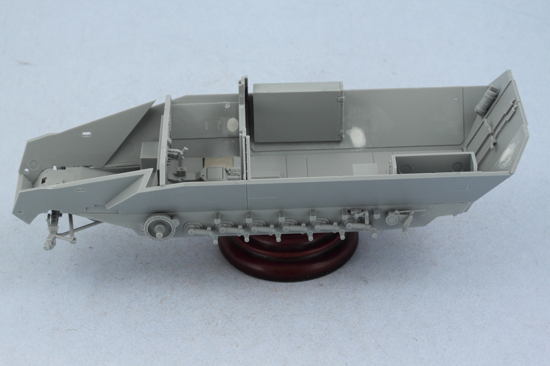
A small test fit with the lower hull and upper hull to make sure everything is playing nice before painting. Definitely shows how cramped the interior was on these vehicles.

Next up will be painting and detailing the interior and the gun!
I started in on Step 16 and selected the b46-b56 style muzzle brake since this is the type featured on the photos included in my Panzer Tracts reference and is the late-but-not-final type of brake commonly seen on Pak 40s in 1944. The tuned aluminum barrel was fitted using CA gel and the breech assembled per the instructions with only a small amount of putty needed at the joins to create a seamless look. I left off the breech lever so it can be detail painted separately and also left the block movable for the same reason.
Step 17 adds the recoil tray and other bits...and has a little pitfall that I didn't catch until it was too late. The instructions show the orientation of the D-shaped pins on parts b26/b27 pointing backwards...I wasn't paying close enough attention to the part numbers and thus installed them on the wrong sides. Of course I used a liberal amount of liquid glue to get a good bond and rather than risk damaging the parts trying to remove them, I ended up carefully snipping off the D pins, reversing them, and re-gluing in the correct position. The pic below is before the surgery.
Step 18 adds the side mounts and their respective details. I left off the elevation and traverse wheels and the gun sight to allow for separate detailing. I used 0.5mm solder and CA gel to add the missing bowden cable to the firing mechanism for a little extra detail. On the right side, the mount pins and holder for the small hatchet were filled in/removed and sanded down since that wasn't a feature on these guns.
Step 19 adds the gun shields and I opted for the PE shutters for the gun sight aperture. The PT reference pics show that the usual Pak 40 storage cylinders weren't mounted (and the instructions indicate those are optional as well) so I filled their mount holes on the inner shield with putty to eliminate them.
A small test fit with the lower hull and upper hull to make sure everything is playing nice before painting. Definitely shows how cramped the interior was on these vehicles.
Next up will be painting and detailing the interior and the gun!
-
Bill Plunk
- Posts: 1245
- Joined: Wed Sep 28, 2022 10:18 pm
WIP 08-19-2012
My next MBA class is gearing up so not as much time at the bench this weekend as I had originally hoped.
Still, I managed to get some additional progress in on the build. I masked off the glue contact surfaces on the hull halves because I hate to scrape paint if I can avoid it. I used MM enamel Italian Dark Brown to prime the interior lower hull, and the interior and exterior of the upper hull as well as the PaK 40. This helps check the putty and other work I had done previously and also ensures I don't end up with any bare plastic spots in the tight places. Then the base coat of 50/50 enamel MM Light Gray/Panzer Dunkelgelb was airbrushed over the primer coat.

I also used the kit-supplied single-round ammo containers and assembled all 10 to stack in the hull void on the left side of the gun mount. These will get some additional weathering and detailing, including the kit decal stencils, prior to installation. Since I was already airbrushing the rest of the interior, they got some paint as well.

That's it for now, the paint will get a chance to fully cure during the week before I start in on the weathering and detailing for the interior.
Still, I managed to get some additional progress in on the build. I masked off the glue contact surfaces on the hull halves because I hate to scrape paint if I can avoid it. I used MM enamel Italian Dark Brown to prime the interior lower hull, and the interior and exterior of the upper hull as well as the PaK 40. This helps check the putty and other work I had done previously and also ensures I don't end up with any bare plastic spots in the tight places. Then the base coat of 50/50 enamel MM Light Gray/Panzer Dunkelgelb was airbrushed over the primer coat.
I also used the kit-supplied single-round ammo containers and assembled all 10 to stack in the hull void on the left side of the gun mount. These will get some additional weathering and detailing, including the kit decal stencils, prior to installation. Since I was already airbrushing the rest of the interior, they got some paint as well.
That's it for now, the paint will get a chance to fully cure during the week before I start in on the weathering and detailing for the interior.
-
Bill Plunk
- Posts: 1245
- Joined: Wed Sep 28, 2022 10:18 pm
WIP 08-23-2012
I decided that I would approach the weathering of the hull interior in a "layered" fashion similar to that I would use on the exterior. To that end, I started the process by stippling some enamel Burnt Umber using an old round sable brush. The brush was treated the same as if I were going to dry-brush but I used a random stabbing motion instead. Very hard on the brush but produces a nice effect.

The Burnt Umber is pretty stark, so to blend it in a bit, I used the same stippling approach but with the base color.

With that foundation laid, I turned to the interior details and added the seat back cushion and also detailed the wood seats. The wood effect was created using a thinned wash of MM enamel Leather over the base coat color followed by a dusting of burnt umber artist pastels. The black leather cushion was painted using a base coat of MM enamel Gunmetal followed by dry-brushed patterns of the base coat color, MM enamel Leather, and a light dry-brush of the enamel Gunmetal to tie it back together.
I installed 9 of the single-round Pak 40 ammo containers after a test fit with the upper hull revealed that the 10th round wouldn't fit properly.

Driver's area received some attention as well. I installed the seat, the gas mask holder, and the various gears and levers. Kit-supplied decals along with Solvaset provided the dashboard instrument detail.

The entire lower hull received a coat of Future to seal in the paint work and initial weathering as a foundation and was left to cure overnight. Then I applied an overall wash of enamel Raw Umber and followed that up with a 2nd wash of enamel Raw Sienna. A pin wash of enamel Burnt Umber was used to bring out some of the panel detail in the floor as well as other details like the hinges on the ammo bins.


Not wanting the interior to be too dark, I went back over the washes with an additional dry-brush pass of the base coat color and further layered/blended things together until I had the look I was after.

I sealed in all the work with a coat of MM Lusterless Flat to remove lingering gloss from the Future and then joined the upper and lower hull halves together. I used rubber bands as a set of "helping hands" at the three strategic points on the hull that wouldn't result in the compartment sides warping in the process. The hull nose plate was added as well to make sure the alignment worked for the later exterior components.

I noticed in the PT reference photo that I've been using that the cleaning rods were tucked away on the left side using the space between the mount brace and the hull as a convenient way to keep them close by but still out of the way of the crew when working the gun. So I dug around in my spares bin and came up with a set of 4 rods from another DML kit, separated them and cleaned them up, then painted and detailed them and arranged them into position. Once I was happy with the way they sat, I used a small amount of liquid glue to secure them in place.
I decided I wasn't going to deploy the rear-mounted MG42 on its mount so it was installed instead in the seat-back bin along with an ammo can from the spares bin.


That's all for now, next up will be detailing the Pak 40 and working on the remaining exterior details.
The Burnt Umber is pretty stark, so to blend it in a bit, I used the same stippling approach but with the base color.
With that foundation laid, I turned to the interior details and added the seat back cushion and also detailed the wood seats. The wood effect was created using a thinned wash of MM enamel Leather over the base coat color followed by a dusting of burnt umber artist pastels. The black leather cushion was painted using a base coat of MM enamel Gunmetal followed by dry-brushed patterns of the base coat color, MM enamel Leather, and a light dry-brush of the enamel Gunmetal to tie it back together.
I installed 9 of the single-round Pak 40 ammo containers after a test fit with the upper hull revealed that the 10th round wouldn't fit properly.
Driver's area received some attention as well. I installed the seat, the gas mask holder, and the various gears and levers. Kit-supplied decals along with Solvaset provided the dashboard instrument detail.
The entire lower hull received a coat of Future to seal in the paint work and initial weathering as a foundation and was left to cure overnight. Then I applied an overall wash of enamel Raw Umber and followed that up with a 2nd wash of enamel Raw Sienna. A pin wash of enamel Burnt Umber was used to bring out some of the panel detail in the floor as well as other details like the hinges on the ammo bins.
Not wanting the interior to be too dark, I went back over the washes with an additional dry-brush pass of the base coat color and further layered/blended things together until I had the look I was after.
I sealed in all the work with a coat of MM Lusterless Flat to remove lingering gloss from the Future and then joined the upper and lower hull halves together. I used rubber bands as a set of "helping hands" at the three strategic points on the hull that wouldn't result in the compartment sides warping in the process. The hull nose plate was added as well to make sure the alignment worked for the later exterior components.
I noticed in the PT reference photo that I've been using that the cleaning rods were tucked away on the left side using the space between the mount brace and the hull as a convenient way to keep them close by but still out of the way of the crew when working the gun. So I dug around in my spares bin and came up with a set of 4 rods from another DML kit, separated them and cleaned them up, then painted and detailed them and arranged them into position. Once I was happy with the way they sat, I used a small amount of liquid glue to secure them in place.
I decided I wasn't going to deploy the rear-mounted MG42 on its mount so it was installed instead in the seat-back bin along with an ammo can from the spares bin.
That's all for now, next up will be detailing the Pak 40 and working on the remaining exterior details.
-
Bill Plunk
- Posts: 1245
- Joined: Wed Sep 28, 2022 10:18 pm
WIP 09-02-2012
The beautiful thing about a 3-day weekend is that it usually results in extra bench time! I made good progress as promised with the first dose of attention going to the PaK 40 details. I applied some light chipping/scuffing using MM enamel Burnt Umber and detailed the breech, hand wheels, and sighting scope off the gun before installing into position.

The recoil tray's bare metal contact surfaces were done using a base layer of MM non-buffing metalizer Steel followed by some dry-brushed enamel Burnt Umber and a light wash of enamel Raw Umber. The block and inner surfaces of the round chamber were done using non-buffing metalizer Steel that was then toned down a bit with some black artist pastels. The rest of the gun will get weathered when the exterior is done so it's not complete, just the details done and installed at this stage.

That brought me back to the exterior and the remaining elements called for in Steps 13 and 14 of the instructions. The bins and fenders were added to both sides with the left side requiring some gap-filling with putty to correct a slight fit issue with the top hull on that side. I added Griffon PE clamps for the axe and pick on both sides and used the kit-supplied brass width indicators. These come straight and a bending guide is provided on the back of sprue C to help get them into the right angle. I lost the kit's mirror due to tweezer-pult and grabbed a replacement off an older HT build that had become a practice/donor kit some time ago. I also used a #76 finger drill and some 0.5mm diameter solder wire to add the missing Bosch headlight wiring conduit that feeds down under the fender and into the hull opening near the front suspension. I also added the empty MG42 swing mount to the top of the hull rear.


The rear hull received some detail attention as well, the fragile details that I'd left off in Step 12 were added in the form of the tow pintle and the rear door handle. I also replaced the inaccurate kit-supplied rear Notek convoy light (it has 5 lenses and is too big) with one from the spares bin that had the correct number of lenses (4) and a better profile. Used the same drill-and-solder combination to create its wiring as well.

The last little detail involved the travel lock from Step 20. The kit instructions are vague and suggest that it installs to the top flat plate over the driver's compartment. This is not the correct position, it actually installs to the angled front plate between the two view port covers. The design of the lock is also incorrect, it has handles on both sides when it should only have a handle on the side facing the driver's visor. I corrected those issues easily enough and also did away with the "pins" on the sides as the kit-provided PE part is too flimsy and too small to be of any use. The lock was glued into position and the gun test fit on the base mount with a bit of blue-tack putty to make sure everything lined up. I'm not showing the gun locked down since the handle is in the "open" position but same sanding/trimming was required at the tops of the lock opening to allow the barrel to fit correctly if the gun were positioned in the slightly downward pointing locked elevation.

That's where she stands so far, next up will be getting some paint on the exterior and perhaps assembling the tracks.
The recoil tray's bare metal contact surfaces were done using a base layer of MM non-buffing metalizer Steel followed by some dry-brushed enamel Burnt Umber and a light wash of enamel Raw Umber. The block and inner surfaces of the round chamber were done using non-buffing metalizer Steel that was then toned down a bit with some black artist pastels. The rest of the gun will get weathered when the exterior is done so it's not complete, just the details done and installed at this stage.
That brought me back to the exterior and the remaining elements called for in Steps 13 and 14 of the instructions. The bins and fenders were added to both sides with the left side requiring some gap-filling with putty to correct a slight fit issue with the top hull on that side. I added Griffon PE clamps for the axe and pick on both sides and used the kit-supplied brass width indicators. These come straight and a bending guide is provided on the back of sprue C to help get them into the right angle. I lost the kit's mirror due to tweezer-pult and grabbed a replacement off an older HT build that had become a practice/donor kit some time ago. I also used a #76 finger drill and some 0.5mm diameter solder wire to add the missing Bosch headlight wiring conduit that feeds down under the fender and into the hull opening near the front suspension. I also added the empty MG42 swing mount to the top of the hull rear.
The rear hull received some detail attention as well, the fragile details that I'd left off in Step 12 were added in the form of the tow pintle and the rear door handle. I also replaced the inaccurate kit-supplied rear Notek convoy light (it has 5 lenses and is too big) with one from the spares bin that had the correct number of lenses (4) and a better profile. Used the same drill-and-solder combination to create its wiring as well.
The last little detail involved the travel lock from Step 20. The kit instructions are vague and suggest that it installs to the top flat plate over the driver's compartment. This is not the correct position, it actually installs to the angled front plate between the two view port covers. The design of the lock is also incorrect, it has handles on both sides when it should only have a handle on the side facing the driver's visor. I corrected those issues easily enough and also did away with the "pins" on the sides as the kit-provided PE part is too flimsy and too small to be of any use. The lock was glued into position and the gun test fit on the base mount with a bit of blue-tack putty to make sure everything lined up. I'm not showing the gun locked down since the handle is in the "open" position but same sanding/trimming was required at the tops of the lock opening to allow the barrel to fit correctly if the gun were positioned in the slightly downward pointing locked elevation.
That's where she stands so far, next up will be getting some paint on the exterior and perhaps assembling the tracks.
-
Bill Plunk
- Posts: 1245
- Joined: Wed Sep 28, 2022 10:18 pm
WIP 09-15-2012
The exterior received some quality time in the paint booth today. I used blue painter's tape to mask off the interior and the detail work already done on the PaK 40 to protect it and mounted all of the road wheels on handy toothpick holders using poster putty and went to work. The rest of the exterior received a primer coat of MM enamel Italian Dark Brown to check all the previous assembly and putty work and provide a foundation to work from for the camouflage pattern.

Rather than apply an overall base coat for the camouflage pattern, I instead applied it over the primer coat one color at a time starting with the green (MM enamel Khaki), then the red-brown (50/50 MM enamel Military Brown/Leather) and then finally the dunkelgelb (50/50 MM enamel Light Gray/Panzer Dunkelgelb). After the pattern was down, I applied a mist coat using the highly thinned remains of the dunkelgelb pass from about 12 inches distance from the model to tie the three-tone scheme together. The PaK 40 is still only dry-fit at this stage.


At the same time as I was working on the exterior pattern, the road wheels got their share of attention as well. They received the same primer coat application and the rubber portions were airbrushed with MM enamel Gunmetal. Using a draftsman's circle template with the appropriate diameter holes masked off, I sprayed the hubs the different colors of the camouflage pattern depending on where they will go on the suspension.

Next up will be working on the tracks and the few remaining exterior details like the tools before heading into the weathering stages.
Rather than apply an overall base coat for the camouflage pattern, I instead applied it over the primer coat one color at a time starting with the green (MM enamel Khaki), then the red-brown (50/50 MM enamel Military Brown/Leather) and then finally the dunkelgelb (50/50 MM enamel Light Gray/Panzer Dunkelgelb). After the pattern was down, I applied a mist coat using the highly thinned remains of the dunkelgelb pass from about 12 inches distance from the model to tie the three-tone scheme together. The PaK 40 is still only dry-fit at this stage.
At the same time as I was working on the exterior pattern, the road wheels got their share of attention as well. They received the same primer coat application and the rubber portions were airbrushed with MM enamel Gunmetal. Using a draftsman's circle template with the appropriate diameter holes masked off, I sprayed the hubs the different colors of the camouflage pattern depending on where they will go on the suspension.
Next up will be working on the tracks and the few remaining exterior details like the tools before heading into the weathering stages.
-
Bill Plunk
- Posts: 1245
- Joined: Wed Sep 28, 2022 10:18 pm
WIP 09-23-2012
One of the neat features in my opinion of DML's 251 family of kits are the workable tracks that they provide. The assembly is fairly straightforward...each link is trapped via a cap block that glues to each pair and if you're careful with the glue, you get workable tracks. The key I've found is to assemble the links in pairs so that the cap blocks have time to dry and be able to do their job of holding the links together. Once the pairs are done, then just daisy-chain them together into groups of 4, then the 4s into 8s, then join the runs together into the single track length needed. I assembled 52 links for each side and will test fit a little further on to determine how many are needed for each side. Because the 251 uses an offset torsion bar suspension, one side will need to be longer than the other...it's just a question of by how much.

With the track runs built, I used them to help with installing the road wheels on both sides. I positioned the inner-most wheels so that the little "D" shaped tab was at the top to provide the most support to the outer wheel halves that attach to them. I also detailed and installed the pot muffler at this point before things got too crowded. The muffler was base coated with MM non-buffing Metalizer Gunmetal and then given an overall wash of enamel Rust. Once dry, the two halves were installed with the top going in first.

I also detailed the pick and axe that install on the front fenders. The metal portions were base coated with the same Metalizer Gunmetal used on the muffler. The tools were lightly dry-brushed with MM enamel Steel. The handles were base-coated with the 50-50 dunkelgelb/light gray mix used on the hull followed by a wash of MM enamel Leather. Once that was dry, I lightly dry-brushed the DY/LG mix to create some variation and pattern and applied a light dusting of raw umber artist pastels to deepen the look a bit. Tools were installed in the PE clamps and secured in place. I also used a bit of Light Gray for the width indicator ball tops instead of white as white tends to be pretty stark on its own. I didn't take a photo but I also detailed the rear Notek convoy light with some Tamiya Clear Green to round things out for the day.

Next up will be sealing it all up and applying the decals (minimal) and getting it ready for weathering.
With the track runs built, I used them to help with installing the road wheels on both sides. I positioned the inner-most wheels so that the little "D" shaped tab was at the top to provide the most support to the outer wheel halves that attach to them. I also detailed and installed the pot muffler at this point before things got too crowded. The muffler was base coated with MM non-buffing Metalizer Gunmetal and then given an overall wash of enamel Rust. Once dry, the two halves were installed with the top going in first.
I also detailed the pick and axe that install on the front fenders. The metal portions were base coated with the same Metalizer Gunmetal used on the muffler. The tools were lightly dry-brushed with MM enamel Steel. The handles were base-coated with the 50-50 dunkelgelb/light gray mix used on the hull followed by a wash of MM enamel Leather. Once that was dry, I lightly dry-brushed the DY/LG mix to create some variation and pattern and applied a light dusting of raw umber artist pastels to deepen the look a bit. Tools were installed in the PE clamps and secured in place. I also used a bit of Light Gray for the width indicator ball tops instead of white as white tends to be pretty stark on its own. I didn't take a photo but I also detailed the rear Notek convoy light with some Tamiya Clear Green to round things out for the day.
Next up will be sealing it all up and applying the decals (minimal) and getting it ready for weathering.
-
Bill Plunk
- Posts: 1245
- Joined: Wed Sep 28, 2022 10:18 pm
WIP 09-30-2012
Continuing on from last week's efforts, I finished up with the tracks. First order of business involved test-fits with the sprockets to see how many links were needed to account for the different suspension lengths on either side. Turned out that I needed 54 links for the left (shorter) side and 56 links for the right (longer) side. Because of the scale effect of the link parts' design and the lack of a movable idler to tension things, this means that the longer side is a little looser than the right but both sag acceptably so no cause for concern.


A quick trip to the spray booth and the tracks received a base coat of MM enamel Burnt Umber. I used strips of masking tape to hold the runs while painting to make life a little easier and ensure paint got into the visible nooks and crannies. Once that had dried, I dry-brushed some MM enamel Steel to create a metallic look followed by a wash of MM enamel Raw Umber to tie things together and tone down the Steel a bit. Final piece of work was to hand-paint the rubber cap blocks individually using MM enamel Gunmetal.

That brought me to the "hurry-up-and-wait" stage of applying the decals. I airbrushed a coat of Future to seal the base coat in preparation for the weathering stages to come and let it air dry for about an hour. Markings for the 251/22s were fairly limited based on available reference photos so I added some crosses to the hull sides and rear and also added the Wehrmacht license plate to the hull nose that seemed to be a common feature. Using the photo from Panzer Tracts 15-3 for the vehicle that I've been replicating in terms of interior details, I used the "number jungle" decal sheet that DML provides to create the plate number WH-1810156 out of individual number decals. Examination of reference photos show that the rear plates weren't a common sight so I left those off on the rear mud flaps.

2nd coat of Future was applied to seal in the decals and it will now sit and cure thoroughly before the weathering process begins next weekend.
A quick trip to the spray booth and the tracks received a base coat of MM enamel Burnt Umber. I used strips of masking tape to hold the runs while painting to make life a little easier and ensure paint got into the visible nooks and crannies. Once that had dried, I dry-brushed some MM enamel Steel to create a metallic look followed by a wash of MM enamel Raw Umber to tie things together and tone down the Steel a bit. Final piece of work was to hand-paint the rubber cap blocks individually using MM enamel Gunmetal.
That brought me to the "hurry-up-and-wait" stage of applying the decals. I airbrushed a coat of Future to seal the base coat in preparation for the weathering stages to come and let it air dry for about an hour. Markings for the 251/22s were fairly limited based on available reference photos so I added some crosses to the hull sides and rear and also added the Wehrmacht license plate to the hull nose that seemed to be a common feature. Using the photo from Panzer Tracts 15-3 for the vehicle that I've been replicating in terms of interior details, I used the "number jungle" decal sheet that DML provides to create the plate number WH-1810156 out of individual number decals. Examination of reference photos show that the rear plates weren't a common sight so I left those off on the rear mud flaps.
2nd coat of Future was applied to seal in the decals and it will now sit and cure thoroughly before the weathering process begins next weekend.