Bronco Panzerjaeger II fuer 7.62cm Pak 36 (Sdkfz 132) Marder II D (2013)
-
Bill Plunk
- Posts: 1245
- Joined: Wed Sep 28, 2022 10:18 pm
Bronco Panzerjaeger II fuer 7.62cm Pak 36 (Sdkfz 132) Marder II D (2013)
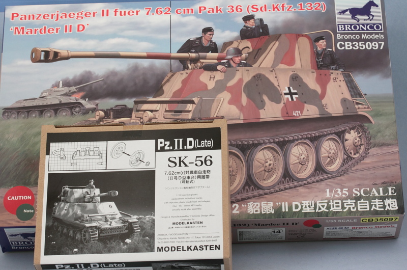
Time to clear the bench and get the next victim ready. This build log will feature Bronco's kit #35097 Panzerjager II 7.62cm Pak 36 (Sd.Kfz.132) Marder II D paired up with a set of Model Kasten SK-56 workable tracks.
-
Bill Plunk
- Posts: 1245
- Joined: Wed Sep 28, 2022 10:18 pm
Re: Bronco Panzerjaeger II fuer 7.62cm Pak 36 (Sdkfz 132) Marder II D (2013)
Time to clear the bench and get the next victim ready. This build log will feature Bronco's kit #35097 Panzerjager II 7.62cm Pak 36 (Sd.Kfz.132) Marder II D paired up with a set of Model Kasten SK-56 workable tracks.
-
Bill Plunk
- Posts: 1245
- Joined: Wed Sep 28, 2022 10:18 pm
WIP 05-18-2013
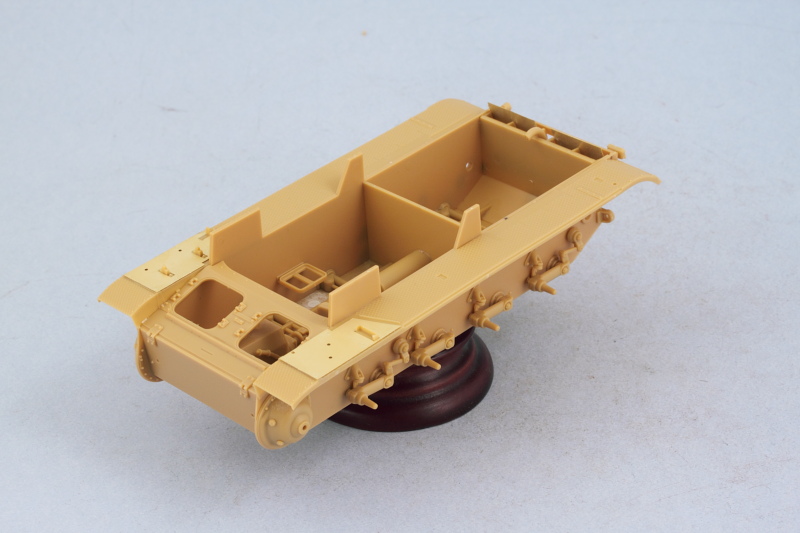
Because Bronco's kit design uses a panel arrangement to construct the lower hull, work began there instead of the usual 'remove and clean-up the road wheels' that typically is the first step for an armor build. Rest assured that will be coming soon, but the first order of business was to construct the lower hull. This is done in the first three steps of the instructions and it pays to study them first and do some test fits as there's a lot that has to go into a relatively small space and play nice with each other in the process.
Step 1 is straightforward, it installs the driver's seat and the torsion bar interior details for the suspension. Ejector marks that would be visible later on where filled with putty and sanded down prior to installing the torsion bar part. This step also calls for attaching the front hull nose armor plate, C18, but I held off doing that until later to make sure it fit just right with the hull side plates.

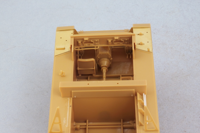
Step 2 has you work on components for the transmission, drive shaft, and brake drums as sub-assemblies to be used in Step 3. I did things a little differently here than in the instructions to make it easier to handle the components and install them into the hull. I installed the drive sprocket shafts, parts J10, to the transmission box directly instead of the to the brake hubs to make it easier to position the transmission box at the right spot in the hull.
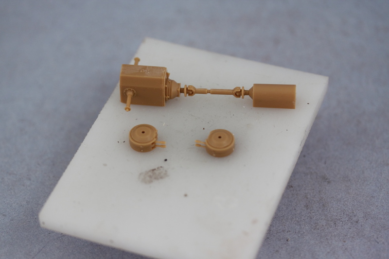
Rather than attach the brake hubs to the transmission box, I installed them directly to the hull sides after doing a test fit to make sure the driver's side hub wouldn't interfere with the driver's seat. Doing things this way gave me some flexibility with the drive shafts in terms of getting things to meet up and do any adjustments when installing the hull sides into position. The base of the loader's seat was also installed but I left the cushion off for now so it could be detailed and installed later on separately.
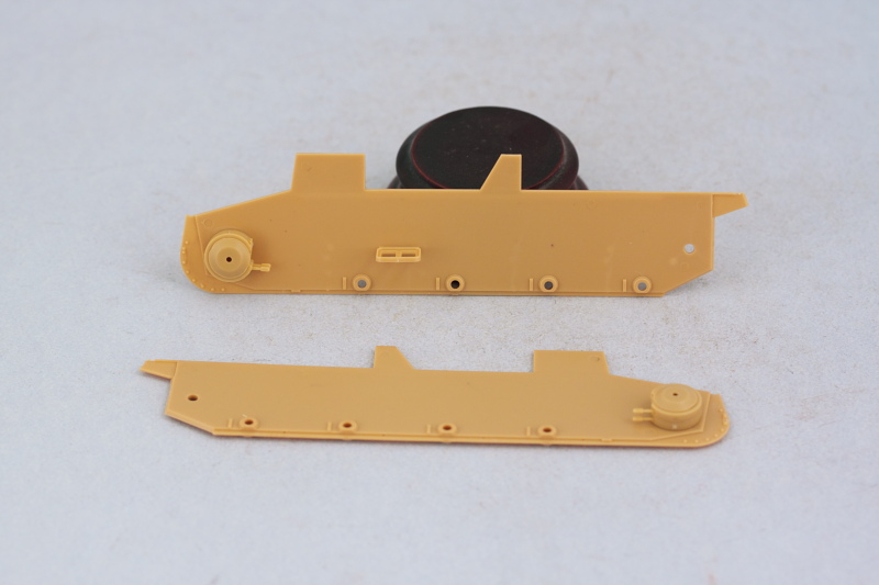
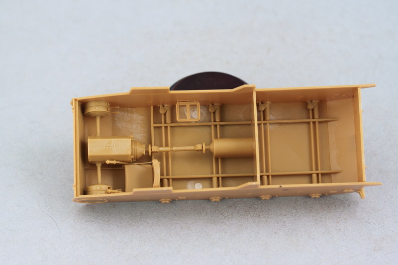
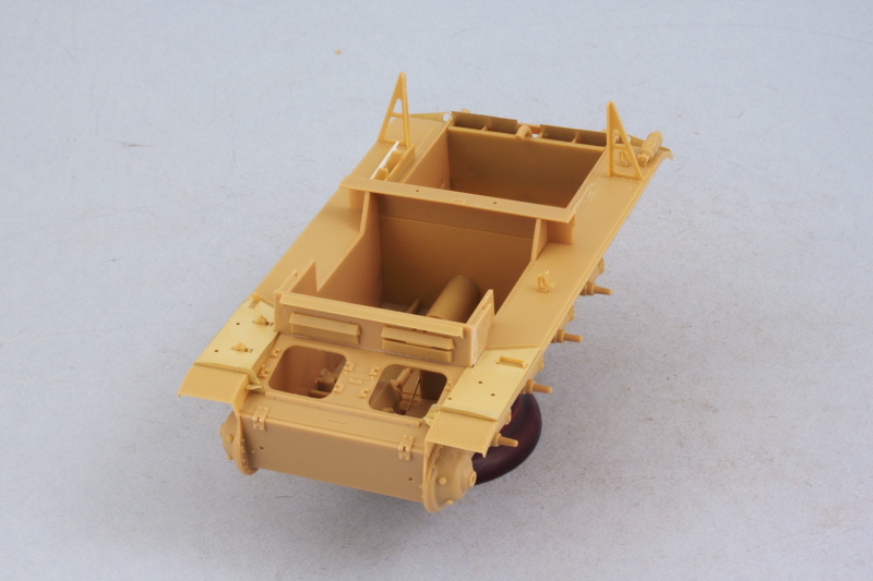
Step 3 brings all the hull components together. Bronco designed the side panels well in terms of how the meet up with the lower hull. There's a small tab at the front that helps keep things lined up and the suspension bar part is also designed to help provide alignment and rigidity at the base. The engine compartment firewall also helps but it fits loosely, so the key to getting it lined up are the slot tabs on its base along with the transmission components that attach to it. That's another reason why I opted for the alternate method of installing the components mentioned earlier after doing some test-fits. The front nose plate was added along with the rear plate. The rear plate's fit required a little finger pressure help to get it to line up properly but otherwise the hull assembled without any major issues.
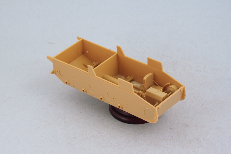
Next up will begin work on the suspension components.
Step 1 is straightforward, it installs the driver's seat and the torsion bar interior details for the suspension. Ejector marks that would be visible later on where filled with putty and sanded down prior to installing the torsion bar part. This step also calls for attaching the front hull nose armor plate, C18, but I held off doing that until later to make sure it fit just right with the hull side plates.
Step 2 has you work on components for the transmission, drive shaft, and brake drums as sub-assemblies to be used in Step 3. I did things a little differently here than in the instructions to make it easier to handle the components and install them into the hull. I installed the drive sprocket shafts, parts J10, to the transmission box directly instead of the to the brake hubs to make it easier to position the transmission box at the right spot in the hull.
Rather than attach the brake hubs to the transmission box, I installed them directly to the hull sides after doing a test fit to make sure the driver's side hub wouldn't interfere with the driver's seat. Doing things this way gave me some flexibility with the drive shafts in terms of getting things to meet up and do any adjustments when installing the hull sides into position. The base of the loader's seat was also installed but I left the cushion off for now so it could be detailed and installed later on separately.
Step 3 brings all the hull components together. Bronco designed the side panels well in terms of how the meet up with the lower hull. There's a small tab at the front that helps keep things lined up and the suspension bar part is also designed to help provide alignment and rigidity at the base. The engine compartment firewall also helps but it fits loosely, so the key to getting it lined up are the slot tabs on its base along with the transmission components that attach to it. That's another reason why I opted for the alternate method of installing the components mentioned earlier after doing some test-fits. The front nose plate was added along with the rear plate. The rear plate's fit required a little finger pressure help to get it to line up properly but otherwise the hull assembled without any major issues.
Next up will begin work on the suspension components.
-
Bill Plunk
- Posts: 1245
- Joined: Wed Sep 28, 2022 10:18 pm
WIP 05-19-2013
Work continued from yesterday's efforts with Steps 4 and 5 which deal with the suspension elements.
Step 4 adds a lot of little parts along with the suspension arms for the road wheels. The instructions direct you to remove 3.1mm from the portions of the arms that mount into the hull, so some surgery is required on all 8 arms. This is due to the fact that the addition of the torsion bar parts on the hull interior (presumably not present in Bronco's earlier Pz II-D kit) blocks off those openings in the hull sides. Easily done with a ruler to mark the cut line, then snip off with sprue cutters and sand down the ends where necessary. The arm bump stops, parts B40, have mount pins on their backs but the pins are too long for them to fit flush, so some sanding is necessary there as well. The idler mount arms were dry-fit only as I need them to remain movable to allow for the workable track tensioning down the road.
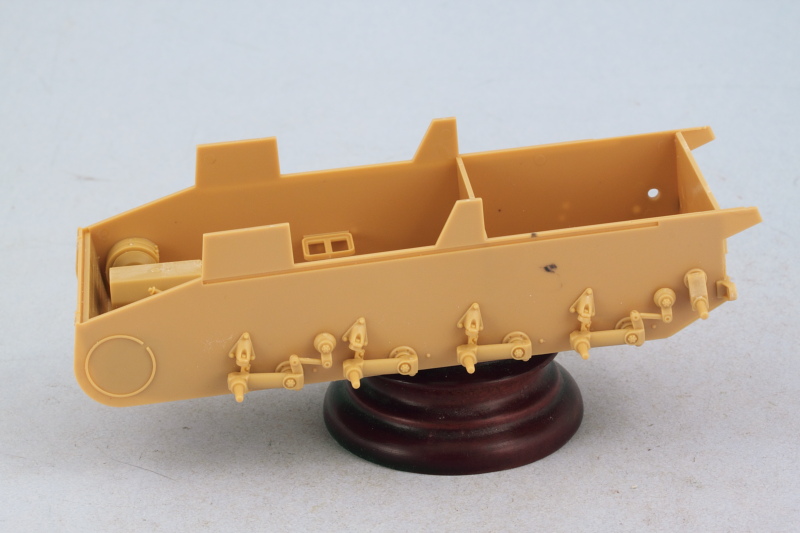
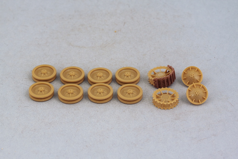
Step 5 deals with the assembly of the road wheels, sprockets, and idlers. The road wheels are separate halves with separate rubber rims as well...and each part has 4 attachment points to be cleaned up. The wheel hubs also had some flash on their inner surfaces that had to be removed, so quite a bit of clean up effort involved with them as a result. The rubber rims fit tightly with a friction fit, so they can be removed easily later on for separate painting but care will be needed to avoid any paint on the insides of the rims and the hubs causing a disruption.
The sprockets assembled easily and I used a run of 10 links from the MK set to ensure the sprocket teeth lined up correctly and would play nice with the tracks later on. That same run was used to test the gap fit on the road wheels as well as the idlers. On the idlers, the front half has small tabs that are supposed to fit into the back halves but the tabs are too tall and have to be trimmed down to all the front half to fit flush at the right gap interval.
Bronco designed the idlers to have a small insert (B21) that's meant to help create a friction fit with the idler swing arm. It's the same part that goes inside each of the road wheels but the difference with the idler arm is that it isn't tapered like the road wheel arms...so it won't fit. It's a good thing I tested that before committing to glue on the idler hub caps, otherwise it would've been harder to fix. The solution is to taper the points of the idler mount arms to match the taper on the road wheel suspension arms with careful trimming/sanding. Don't add part B23 (the idler tension bolt) at this stage unless you're sure about the position you need for the idler...I'm not, so that will get added later.
A test fit with all the parts from Step 5 was carried out to make sure everything lined up properly. Installation will occur later on after painting.
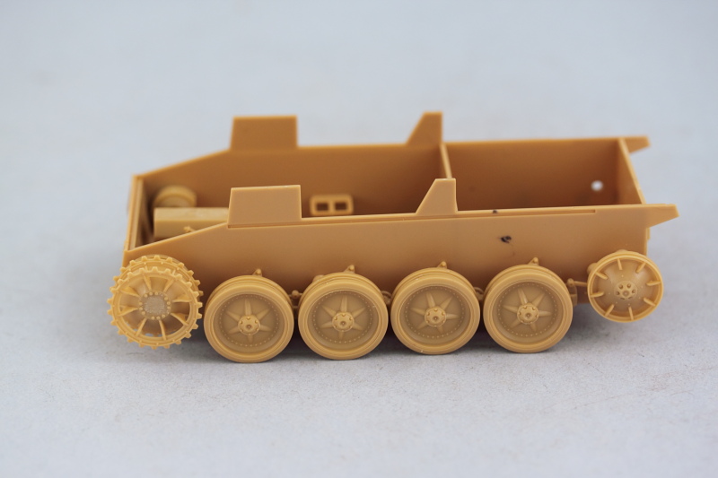
Next up will be working on the rear hull details and then on to the fenders.
Step 4 adds a lot of little parts along with the suspension arms for the road wheels. The instructions direct you to remove 3.1mm from the portions of the arms that mount into the hull, so some surgery is required on all 8 arms. This is due to the fact that the addition of the torsion bar parts on the hull interior (presumably not present in Bronco's earlier Pz II-D kit) blocks off those openings in the hull sides. Easily done with a ruler to mark the cut line, then snip off with sprue cutters and sand down the ends where necessary. The arm bump stops, parts B40, have mount pins on their backs but the pins are too long for them to fit flush, so some sanding is necessary there as well. The idler mount arms were dry-fit only as I need them to remain movable to allow for the workable track tensioning down the road.
Step 5 deals with the assembly of the road wheels, sprockets, and idlers. The road wheels are separate halves with separate rubber rims as well...and each part has 4 attachment points to be cleaned up. The wheel hubs also had some flash on their inner surfaces that had to be removed, so quite a bit of clean up effort involved with them as a result. The rubber rims fit tightly with a friction fit, so they can be removed easily later on for separate painting but care will be needed to avoid any paint on the insides of the rims and the hubs causing a disruption.
The sprockets assembled easily and I used a run of 10 links from the MK set to ensure the sprocket teeth lined up correctly and would play nice with the tracks later on. That same run was used to test the gap fit on the road wheels as well as the idlers. On the idlers, the front half has small tabs that are supposed to fit into the back halves but the tabs are too tall and have to be trimmed down to all the front half to fit flush at the right gap interval.
Bronco designed the idlers to have a small insert (B21) that's meant to help create a friction fit with the idler swing arm. It's the same part that goes inside each of the road wheels but the difference with the idler arm is that it isn't tapered like the road wheel arms...so it won't fit. It's a good thing I tested that before committing to glue on the idler hub caps, otherwise it would've been harder to fix. The solution is to taper the points of the idler mount arms to match the taper on the road wheel suspension arms with careful trimming/sanding. Don't add part B23 (the idler tension bolt) at this stage unless you're sure about the position you need for the idler...I'm not, so that will get added later.
A test fit with all the parts from Step 5 was carried out to make sure everything lined up properly. Installation will occur later on after painting.
Next up will be working on the rear hull details and then on to the fenders.
-
Bill Plunk
- Posts: 1245
- Joined: Wed Sep 28, 2022 10:18 pm
WIP 05-25-2013
Taking full advantage of the Memorial Day extended holiday (and of course taking time to also remember and honor all of those who have died in service to their country!), work continued with the focus shifting to the upper hull and fenders.
Steps 6 and 7 deal with the rear hull details with Step 6 assembling the air exhaust deflectors, the muffler and heat shield, and the tow hitch. The heat shield was annealed over the gas burner flame on my kitchen stove, then curved to shape using the metal handle of my Xacto knife to get it close to the required curve and the muffler itself served as the former to get it curved the rest of the way. I drilled out the muffler exhaust pipe since the kit supplied part just had a molded depression for its mouth.
These parts were installed in Step 7 along with the rear hull overhang plate that includes the Notek rear light and standard brake lights. The engine exhaust extension pipe was installed as well to round things out.
Step 8 is a simple step, it installs the driver's instrument panel under the hull glacis plate as well as the driver's long grab handle, part E19. I added the grab handle later on after realizing as I wrote this that I had neglected to install it. The glacis plate was added to the front hull and fit beautifully, no clearance issues at all with the instrument panel and the transmission.
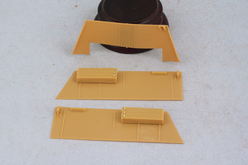
Steps 9 to 11 deal with the fenders and while the instructions have you put all the details on the fenders first and then install them, that's generally not a good idea so I switched things around a little bit. Both fenders were added after receiving their kit-supplied PE blanking plates for the tool mounts.
Next up will be adding all the various details (except the tools) to the fenders and starting work on the gun base mount.
Steps 6 and 7 deal with the rear hull details with Step 6 assembling the air exhaust deflectors, the muffler and heat shield, and the tow hitch. The heat shield was annealed over the gas burner flame on my kitchen stove, then curved to shape using the metal handle of my Xacto knife to get it close to the required curve and the muffler itself served as the former to get it curved the rest of the way. I drilled out the muffler exhaust pipe since the kit supplied part just had a molded depression for its mouth.
These parts were installed in Step 7 along with the rear hull overhang plate that includes the Notek rear light and standard brake lights. The engine exhaust extension pipe was installed as well to round things out.
Step 8 is a simple step, it installs the driver's instrument panel under the hull glacis plate as well as the driver's long grab handle, part E19. I added the grab handle later on after realizing as I wrote this that I had neglected to install it. The glacis plate was added to the front hull and fit beautifully, no clearance issues at all with the instrument panel and the transmission.
Steps 9 to 11 deal with the fenders and while the instructions have you put all the details on the fenders first and then install them, that's generally not a good idea so I switched things around a little bit. Both fenders were added after receiving their kit-supplied PE blanking plates for the tool mounts.
Next up will be adding all the various details (except the tools) to the fenders and starting work on the gun base mount.
-
Bill Plunk
- Posts: 1245
- Joined: Wed Sep 28, 2022 10:18 pm
WIP 05-26-2013
More progress to report today so let's get right down to it!
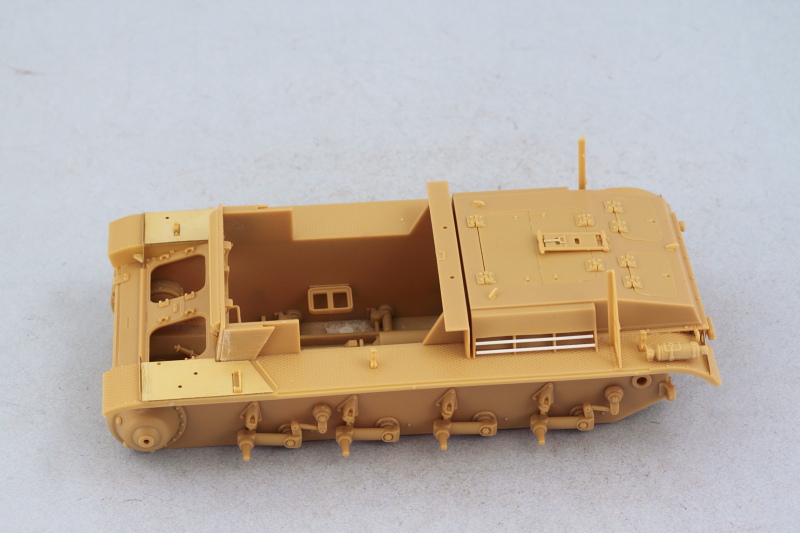
Work continued on the fenders with the addition of many of the details called for in Steps 9-11. The right side received the engine air intake and I replaced the flimsy kit supplied PE bars with rod styrene. Turns out later on in the build that this area is completely hidden away so it's not that critical either way. What is critical is the placement of the intakes and after placing the first one and doing some test fits with the rear engine deck, I realized it's actually much easier to install the intakes into the engine deck vs. trying to place them precisely on the fenders...so that's why only one is installed in the pic below.

You do need to be sure you choose the correct engine deck as there are two in the kit. I mistakenly did my test fits with the standard deck used on the II-D instead of the slightly modified one for the Marder II. Fortunately they are the same dimensions with the same placement so not a huge deal. Here you can see how the intakes fit into the deck vs. trying to place them on the fenders. I also had to modify the kit-supplied fire extinguisher by removing the rear mount pin and sanding down that area as the kit would have you leave the pin just hanging in mid-air over the fender and looking very out of place in the process.

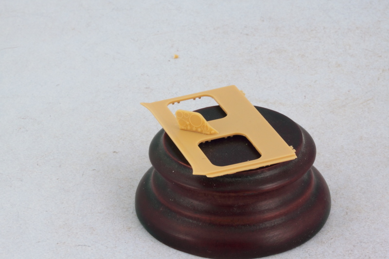
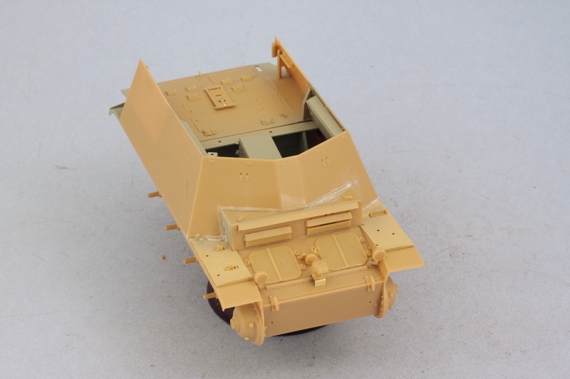
Step 12 deals with the front hull driver's plate and provides the option of installing the visors either open or closed. I closed the right side since there isn't a crew member in that position regardless but posed the driver's side visor open. The rear portion of the gun mount also installed over the firewall to round things out in this step.
There's a lot of very nice detail provided on the interior side of the plate, but no armored glass blocks.
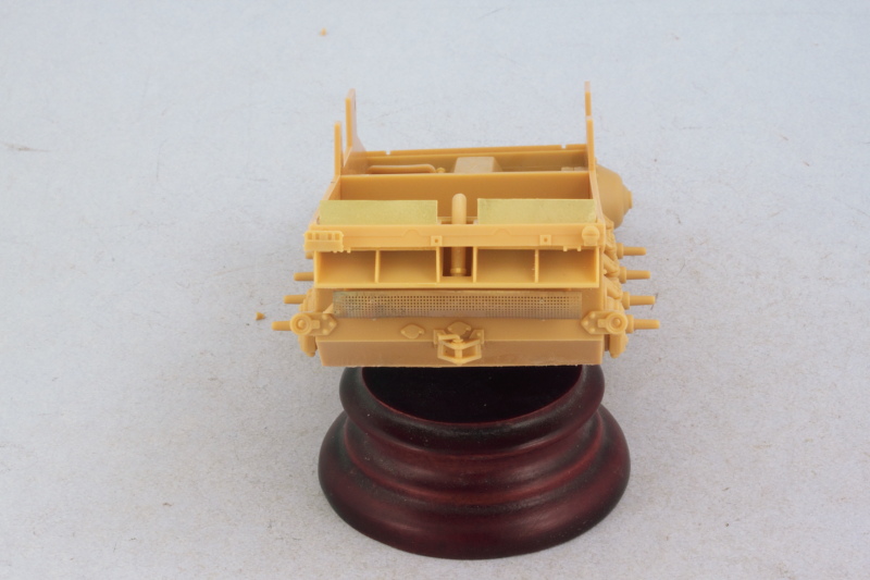
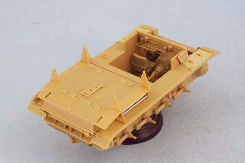
Skipping ahead a bit, I went to Step 15 to work on the rear engine deck (using the correct part this time!) and installed that in position on the hull. Once that had set up, I added all the access hatches, hinges, and lifting hooks. Bronco likes to do a lot of little parts with some of the assemblies and the rear travel lock for the main gun has this tiny little hinge trap part with tiny little pins on the lock itself. I suppose if you were really careful it could remain movable but I chose to lock it down in the stowed position.
Again skipping a bit, I proceeded to Step 17 to install the rear fighting platform extensions. It's these extensions that render the previous intake work virtually unseen and the tolerances here are tight. They are designed to fit tightly over the triangular brace supports added earlier and fit flush against the hull, so if your placement of either the fenders or the braces is just a touch off, you'll have to use some elbow grease to get everything back into proper alignment. I found the little PE bracing struts for the extension to be too tall to sit properly so didn't use them as this area is practically hidden from view regardless once the fighting compartment side armor is fitted and the mesh screens in place.
After giving it some careful thought in terms of how best to tackle the interior painting and detailing work, I decided to leave the driver's roof plate off and keep the large 8-round ammo box and gun mount base parts separate. The roof plate received its details as called for in Steps 13-14 and the gun mount base was assembled per Step 18. The vehicle's radio receiver unit was installed into the PE frame and then in position under the roof with a small hole drilled with a #76 finger drill to take the antenna wiring later on when it's installed.
The large ammo box is taken care of in Step 16. Here again is Bronco's small part tendency on display, the box is made up of two large parts but 8 tiny PE handles and another 8 tiny plastic wing nuts to get it assembled. The PE is extremely fragile and the handles are all connected together on the PE fret, making it a delicate job to remove them cleanly without bending or distorting their shapes in the process.
Next up will begin work on the fighting compartment side panels.
Work continued on the fenders with the addition of many of the details called for in Steps 9-11. The right side received the engine air intake and I replaced the flimsy kit supplied PE bars with rod styrene. Turns out later on in the build that this area is completely hidden away so it's not that critical either way. What is critical is the placement of the intakes and after placing the first one and doing some test fits with the rear engine deck, I realized it's actually much easier to install the intakes into the engine deck vs. trying to place them precisely on the fenders...so that's why only one is installed in the pic below.
You do need to be sure you choose the correct engine deck as there are two in the kit. I mistakenly did my test fits with the standard deck used on the II-D instead of the slightly modified one for the Marder II. Fortunately they are the same dimensions with the same placement so not a huge deal. Here you can see how the intakes fit into the deck vs. trying to place them on the fenders. I also had to modify the kit-supplied fire extinguisher by removing the rear mount pin and sanding down that area as the kit would have you leave the pin just hanging in mid-air over the fender and looking very out of place in the process.
Step 12 deals with the front hull driver's plate and provides the option of installing the visors either open or closed. I closed the right side since there isn't a crew member in that position regardless but posed the driver's side visor open. The rear portion of the gun mount also installed over the firewall to round things out in this step.
There's a lot of very nice detail provided on the interior side of the plate, but no armored glass blocks.
Skipping ahead a bit, I went to Step 15 to work on the rear engine deck (using the correct part this time!) and installed that in position on the hull. Once that had set up, I added all the access hatches, hinges, and lifting hooks. Bronco likes to do a lot of little parts with some of the assemblies and the rear travel lock for the main gun has this tiny little hinge trap part with tiny little pins on the lock itself. I suppose if you were really careful it could remain movable but I chose to lock it down in the stowed position.
Again skipping a bit, I proceeded to Step 17 to install the rear fighting platform extensions. It's these extensions that render the previous intake work virtually unseen and the tolerances here are tight. They are designed to fit tightly over the triangular brace supports added earlier and fit flush against the hull, so if your placement of either the fenders or the braces is just a touch off, you'll have to use some elbow grease to get everything back into proper alignment. I found the little PE bracing struts for the extension to be too tall to sit properly so didn't use them as this area is practically hidden from view regardless once the fighting compartment side armor is fitted and the mesh screens in place.
After giving it some careful thought in terms of how best to tackle the interior painting and detailing work, I decided to leave the driver's roof plate off and keep the large 8-round ammo box and gun mount base parts separate. The roof plate received its details as called for in Steps 13-14 and the gun mount base was assembled per Step 18. The vehicle's radio receiver unit was installed into the PE frame and then in position under the roof with a small hole drilled with a #76 finger drill to take the antenna wiring later on when it's installed.
The large ammo box is taken care of in Step 16. Here again is Bronco's small part tendency on display, the box is made up of two large parts but 8 tiny PE handles and another 8 tiny plastic wing nuts to get it assembled. The PE is extremely fragile and the handles are all connected together on the PE fret, making it a delicate job to remove them cleanly without bending or distorting their shapes in the process.
Next up will begin work on the fighting compartment side panels.
-
Bill Plunk
- Posts: 1245
- Joined: Wed Sep 28, 2022 10:18 pm
WIP 05-27-2013
Had a blast watching Star Trek: Into Darkness so that took up a good chunk of the day but also got in some more time as part of the 3-day weekend on the Marder.
My original plan was to install the front portion of the fighting compartment to the driver's roof plate and use that as a single unit for painting and detailing. That was shelved when I discovered that the front compartment plate had a slight warp to it that will have to be dealt with when it is installed along with the side plates later on, so it's left separate for now. I did add the base of the antenna mount to it and also worked on the side plates as called for in Steps 21-23. The three-round ammo boxes were assembled (each is a 10 part assembly including the PE details) and installed as were the mount plates for the crew seats and the base of the tarp support rails.
Rounding out the day's efforts, I returned to the previous steps and installed the remaining front hull details. The front hatches were installed along with the main headlights, the Notek light, and the siren.
Next weekend should see some paint and detailing work done on the lower hull interior as well as more progress on the fighting compartment elements.
-
Bill Plunk
- Posts: 1245
- Joined: Wed Sep 28, 2022 10:18 pm
WIP 06-02-2013
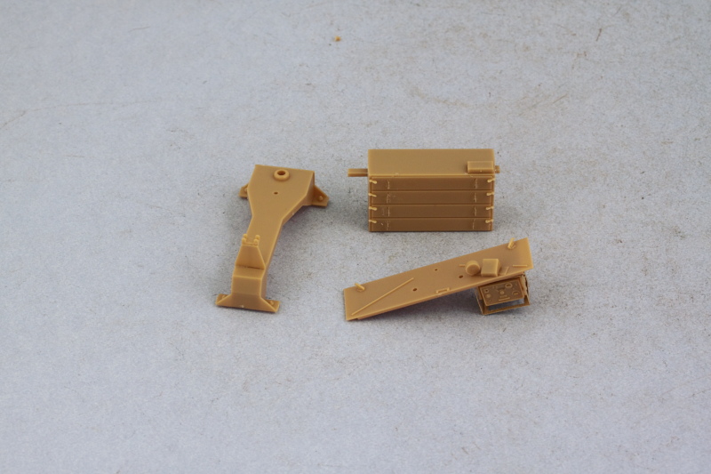
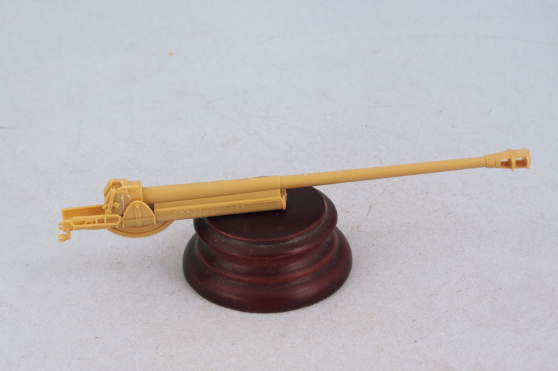
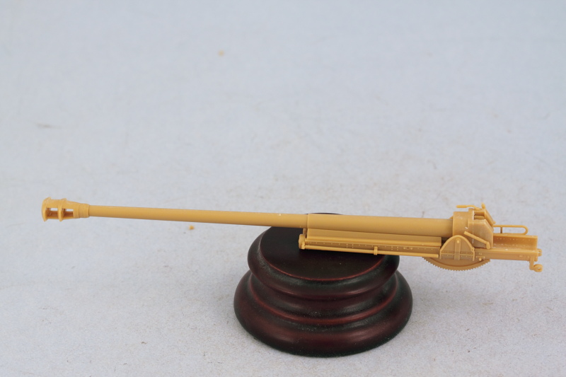
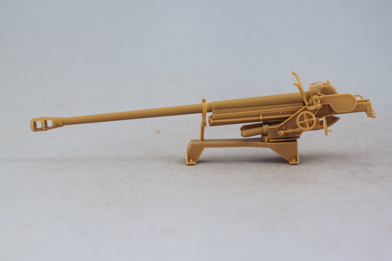
I didn't get a solid enough block of time to do paint work so instead focused my efforts on the Pak 36(r) main gun. Step 28 assembles the breech, the recoil tray, the gun barrel and muzzle brake, and the recoil sled as a multi-sub-assembly process. Lots of parts involved in this step, 23 in total. Some putty and sanding work was necessary on the breech to get a seamless result, but otherwise everything else went together smoothly. The gun barrel is one piece with separate multiple pieces for the muzzle brake with the barrel having only a very fine seam that is easily sanded away. I left the recoil sled unglued as directed in the instructions as this will make it much easier to paint and detail things later on.
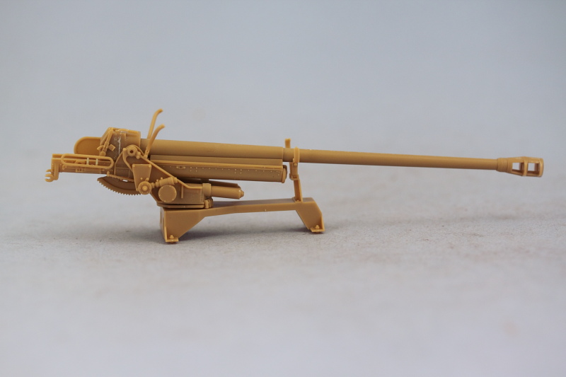
Step 29 addresses the gun mount and various details for the sides of the mounts. The instructions would have you attach all the fine/delicate parts to the mount sides first and then join the sides together along with the work done in Step 28 but that's not really a good idea given just how tiny/fragile some of those details are. This step has 28 parts so a lot going on here as well including separate tiny knobs for the elevation and traverse wheels. If done with care, the gun will remain able to elevate. I left off the gunner's sight for now as it will be detailed later. There is a small error in the instructions, the little diagram showing how G12 attaches to G52 has G52 upside down vs. how it really should be and is shown correctly in the main diagram in the step. I also looked ahead at Step 33 and added the small parts F23 and F26 at this stage and also installed the mount base plate F5 to the base frame assembled previously in Step 18 along with the front travel lock parts in the open position. The gun itself is dry fit only to the base frame to allow for flexibility in the paint and detail areas.
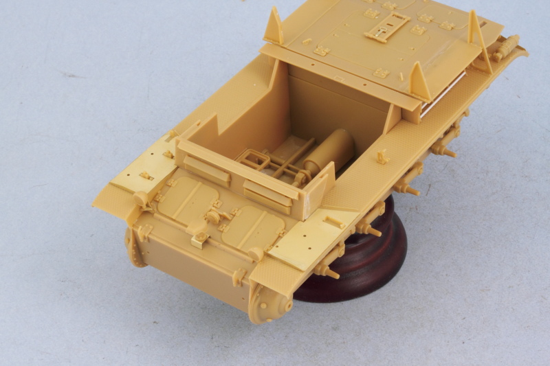
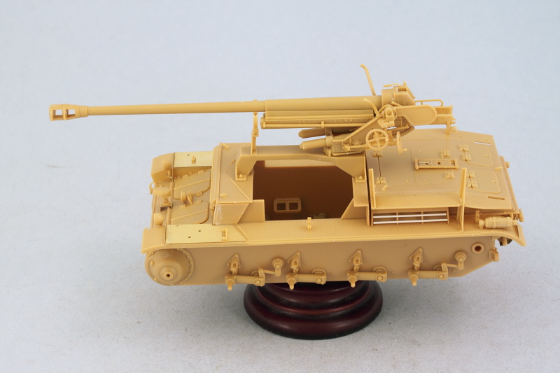
Just to make sure everything was playing nice, I did a test fit with the driver's roof plate and the main hull.
Next up will be working on the splinter shield and its details to get it ready for paint.
Step 29 addresses the gun mount and various details for the sides of the mounts. The instructions would have you attach all the fine/delicate parts to the mount sides first and then join the sides together along with the work done in Step 28 but that's not really a good idea given just how tiny/fragile some of those details are. This step has 28 parts so a lot going on here as well including separate tiny knobs for the elevation and traverse wheels. If done with care, the gun will remain able to elevate. I left off the gunner's sight for now as it will be detailed later. There is a small error in the instructions, the little diagram showing how G12 attaches to G52 has G52 upside down vs. how it really should be and is shown correctly in the main diagram in the step. I also looked ahead at Step 33 and added the small parts F23 and F26 at this stage and also installed the mount base plate F5 to the base frame assembled previously in Step 18 along with the front travel lock parts in the open position. The gun itself is dry fit only to the base frame to allow for flexibility in the paint and detail areas.
Just to make sure everything was playing nice, I did a test fit with the driver's roof plate and the main hull.
Next up will be working on the splinter shield and its details to get it ready for paint.
-
Bill Plunk
- Posts: 1245
- Joined: Wed Sep 28, 2022 10:18 pm
WIP 06-09-2013
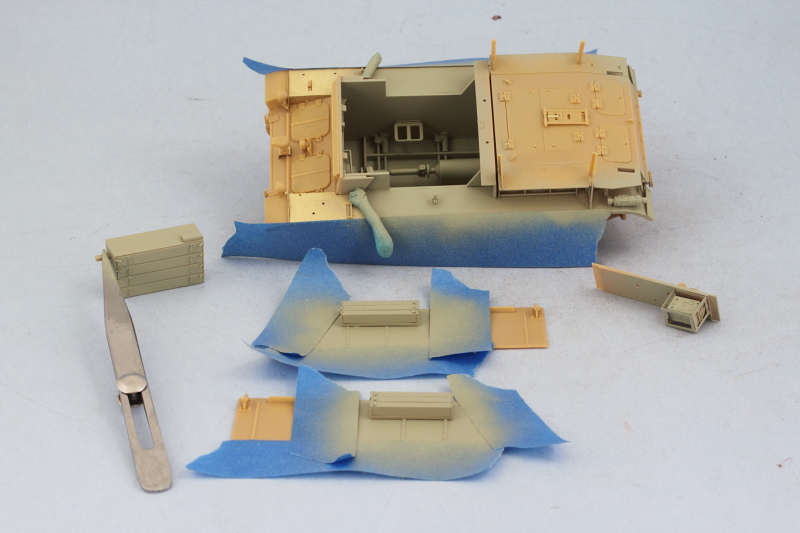
After some careful thought, I decided to go ahead and paint and detail the lower interior of the fighting compartment before doing any more work on the gun and splinter shield. The vast majority of the interior is hidden away once the gun is mounted and the splinter shield in place so I was selective in terms of what was painted and detailed and what wasn't as a result.
First up, I airbrushed a 50-50 mix of Model Master enamel Light Gray/Panzer Dunkelgelb over the various interior components from previous steps. Strips of blue painter's tape were used to mask off the critical join points on the compartment sides and on the fenders to avoid having to scrape paint and ensure a good join was possible down the road.
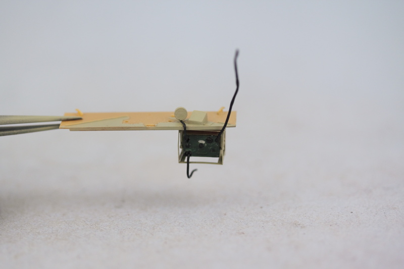
Next I spent some time on the radio, adding wiring for the loud speaker, a power plug that disappears into the driver's compartment, and the cable for the antenna. 0.5mm solder was used for the wiring and carefully bent to shape as needed and then glued into place with CA gel.
The driver's roof panel was installed into place and some light wear/scuffing added to the interior by stippling some enamel Burnt Umber in various spots. The radio operator's seat was also detailed and added at this point as were the gun cleaning rods.
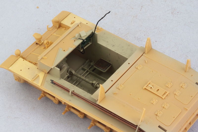
With that out of the way, I installed the large ammo bin that sits under the gun mount and installed the compartment side walls. This was essential due to the warped condition of the angled front compartment plate as the side panels were going to help provide some much needed leverage to get it into the correct position. I used regular glue at the bottoms and liquid glue along the angled braces and hull side extension plates to ensure they were solid and lined up correctly.
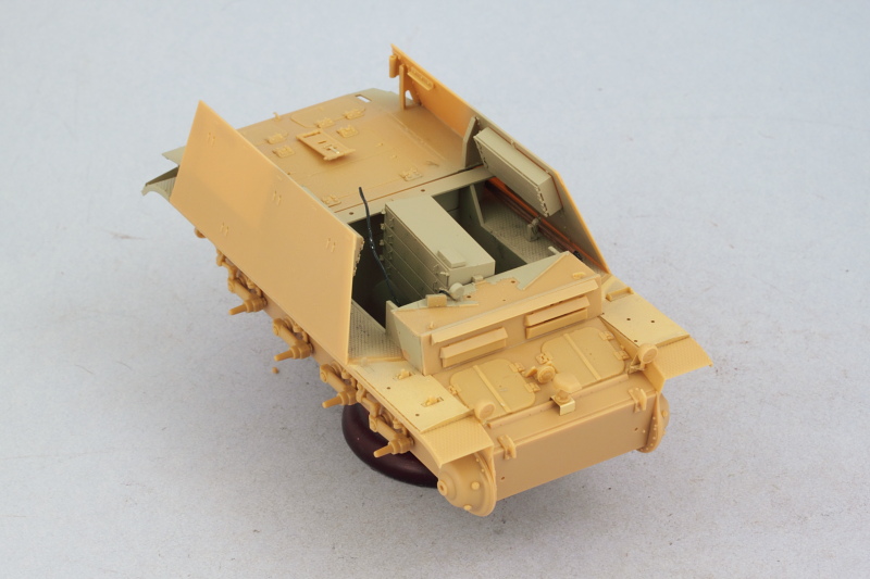
Last but not least for the day, the front panel was installed. It's a thin panel to begin with which is why I think it had the slight warp to begin with so care was necessary when installing it not to create a distortion from one side to the other with finger pressure. Prior to installing it, I airbrushed the same 50/50 mix from earlier on it's interior side as my original plan of painting it in place post-install turned out to be less than ideal due to the space constraints. After the glue had set, some small amounts of putty and sanding were needed at the base in various places to fill small gaps that couldn't be closed otherwise.
Next up will be getting the rest of the compartment painted and detailed and then return to working on the gun components.
First up, I airbrushed a 50-50 mix of Model Master enamel Light Gray/Panzer Dunkelgelb over the various interior components from previous steps. Strips of blue painter's tape were used to mask off the critical join points on the compartment sides and on the fenders to avoid having to scrape paint and ensure a good join was possible down the road.
Next I spent some time on the radio, adding wiring for the loud speaker, a power plug that disappears into the driver's compartment, and the cable for the antenna. 0.5mm solder was used for the wiring and carefully bent to shape as needed and then glued into place with CA gel.
The driver's roof panel was installed into place and some light wear/scuffing added to the interior by stippling some enamel Burnt Umber in various spots. The radio operator's seat was also detailed and added at this point as were the gun cleaning rods.
With that out of the way, I installed the large ammo bin that sits under the gun mount and installed the compartment side walls. This was essential due to the warped condition of the angled front compartment plate as the side panels were going to help provide some much needed leverage to get it into the correct position. I used regular glue at the bottoms and liquid glue along the angled braces and hull side extension plates to ensure they were solid and lined up correctly.
Last but not least for the day, the front panel was installed. It's a thin panel to begin with which is why I think it had the slight warp to begin with so care was necessary when installing it not to create a distortion from one side to the other with finger pressure. Prior to installing it, I airbrushed the same 50/50 mix from earlier on it's interior side as my original plan of painting it in place post-install turned out to be less than ideal due to the space constraints. After the glue had set, some small amounts of putty and sanding were needed at the base in various places to fill small gaps that couldn't be closed otherwise.
Next up will be getting the rest of the compartment painted and detailed and then return to working on the gun components.
-
Bill Plunk
- Posts: 1245
- Joined: Wed Sep 28, 2022 10:18 pm
WIP 06-15-2013
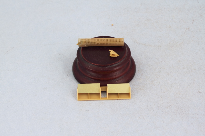
Got some time in today on the Marder and it was a 'fun with PE' day in more ways than one. The entire rear 'cage' of the fighting compartment is assembled out of PE and the frame consists of a single large piece of PE on the fret that requires multiple bends to get it formed properly. It's also necessary to remove a lot of other PE parts that are positioned on the fret inside the frame, creating lots of little nubs for cleanup in the process, so it's necessary to go slow and use a sharp knife to remove everything without damage.
All of the bends went smoothly right up until the last one involving the top portion of the frame that bends outward to from the top angle. I use different bending tools including an Etch Mate, a Fender Bender, and various flat pliers and tweezers when I work with PE and this complex piece required all of them in various places to get it shaped correctly. The last bend though resulted in some buckling of the middle frames and very nearly represented a disaster in the making and I halted the bend before it was at 90 degrees when I saw what was happening.

This very nearly derailed the entire effort but I resolved to try to salvage it and using the tweezers, pliers, and careful back and forth straightening, was able to get it back into shape and create the necessary bend. I used CA gel to install the base to the rear hull as well as attach the edges where they mate up with the solid plates of the fighting compartment sides.
It's worth noting at this point that the instruction diagram contains an error...the small tab on the far left side of the frame is meant to be a support for the fire extinguisher (now I know why the mount pin was left on it in the previous diagrams, that pin is supposed to go into the tab) and not attach to the compartment floor extension as the arrow indicates. It is also necessary to get the bend angle on the side 'wing' portions of the frame at the correct angle and remove one of the raised bolts on the rear fender to allow the frame to sit at the correct height and orientation to the compartment sides.

Next came the addition of the PE mesh to the frame. The attachment points of the mesh to the frame are tiny, so I decided to use Future as the glue of choice to secure the screens in place instead of CA to avoid potential mess and glue accumulations. Future was brushed on the frames and the mesh positioned and carefully held in place until the Future grabbed hold. Then I carefully rolled a wooden toothpick along the edges of the mesh to ensure they conformed to the frame and didn't produce any tension. Additional Future was used where needed along with direct pressure to tack down the screen edges.
This was the first time I'd used Future as a glue even though I'd read about other builders using it for small/delicate parts. Once it had dried, it held the mesh even when I tested it from the inside of the frame by pushing gently on it with a brush handle end. I needed to be sure the mesh wouldn't go flying when subjected to the air pressure from the airbrush during painting and the brush handle test showed it would stay put, so that's a technique I'll definitely be using again in the 'future'!
Last but not least, I added the exterior frame ribs over the mesh as directed in the instructions and placed the rear bracket for the crow bar mount to round things out for the day.

Next up will be laying down some paint on the interior so it can get ready for its finishing details and weathering.
All of the bends went smoothly right up until the last one involving the top portion of the frame that bends outward to from the top angle. I use different bending tools including an Etch Mate, a Fender Bender, and various flat pliers and tweezers when I work with PE and this complex piece required all of them in various places to get it shaped correctly. The last bend though resulted in some buckling of the middle frames and very nearly represented a disaster in the making and I halted the bend before it was at 90 degrees when I saw what was happening.
This very nearly derailed the entire effort but I resolved to try to salvage it and using the tweezers, pliers, and careful back and forth straightening, was able to get it back into shape and create the necessary bend. I used CA gel to install the base to the rear hull as well as attach the edges where they mate up with the solid plates of the fighting compartment sides.
It's worth noting at this point that the instruction diagram contains an error...the small tab on the far left side of the frame is meant to be a support for the fire extinguisher (now I know why the mount pin was left on it in the previous diagrams, that pin is supposed to go into the tab) and not attach to the compartment floor extension as the arrow indicates. It is also necessary to get the bend angle on the side 'wing' portions of the frame at the correct angle and remove one of the raised bolts on the rear fender to allow the frame to sit at the correct height and orientation to the compartment sides.
Next came the addition of the PE mesh to the frame. The attachment points of the mesh to the frame are tiny, so I decided to use Future as the glue of choice to secure the screens in place instead of CA to avoid potential mess and glue accumulations. Future was brushed on the frames and the mesh positioned and carefully held in place until the Future grabbed hold. Then I carefully rolled a wooden toothpick along the edges of the mesh to ensure they conformed to the frame and didn't produce any tension. Additional Future was used where needed along with direct pressure to tack down the screen edges.
This was the first time I'd used Future as a glue even though I'd read about other builders using it for small/delicate parts. Once it had dried, it held the mesh even when I tested it from the inside of the frame by pushing gently on it with a brush handle end. I needed to be sure the mesh wouldn't go flying when subjected to the air pressure from the airbrush during painting and the brush handle test showed it would stay put, so that's a technique I'll definitely be using again in the 'future'!
Last but not least, I added the exterior frame ribs over the mesh as directed in the instructions and placed the rear bracket for the crow bar mount to round things out for the day.
Next up will be laying down some paint on the interior so it can get ready for its finishing details and weathering.