Dragon Neubau-Fahrzeug Nr. 3-5 (2013)

Bill Plunk
Posts: 1245
Joined: Wed Sep 28, 2022 10:18 pm

Dragon Neubau-Fahrzeug Nr. 3-5 (2013)

Post by Bill Plunk »

Build log for DML's kit #6690, Neubau-Fahrzeug Nr. 3-5 Rheinmetall-Fahrestall und Krupp-Turm Geanderte MG-Turme (try saying that 3x fast!) :)

Build will be done OOB.

Image
Bill Plunk
Posts: 1245
Joined: Wed Sep 28, 2022 10:18 pm

WIP 12-16-2012

Post by Bill Plunk »

Got this one off and rolling with the usual hurdle coming first in the form of the road wheels. The Germans were suckers for lots of wheels and the Neubau doesn't disappoint in that area. Beginning with Step 1, I cleaned up the mold seams on each of the wheel halves with a sanding stick and assembled the pairs. 11 main wheels per side plus 1 idler pair plus 4 return rollers made for no less than 32 wheels per side or 64 in total. The sprockets were also assembled at this point to go with everything else.

Image

Those wheels will need to be painted prior to installation into the suspension due to the way the suspension is designed which is what is addressed in Step 2. The vast majority of parts in the kit are devoted to the suspension (and tracks) due to the vehicle's design. This step calls for the construction of the wheel pairs and their installation into the long plates that go into the hull sponsons. I checked to see if it's possible to add the plates without the wheel pairs installed and the design doesn't allow for that, so the plates were left uninstalled until after the wheel pairs are painted and installed. I did assemble the bogey halves, the instructions contain an error in that the parts should be paired up with D11 going with D23 and D12 going with D24. I also added the mount halves for the large idler wheel that support the 11th wheel on either side.

Image

Step 2 also adds the sprockets and their capture plates as well as a couple of hatches for the sponson sides. Step 3 adds the hull belly plate to the large one-piece hull and also adds the rear plate and some other small details like the access hatch, brake light, and tow points.

Image

Image

That's as far as things got for this round, next up will be doing the paint work and detailing on the suspension.
Bill Plunk
Posts: 1245
Joined: Wed Sep 28, 2022 10:18 pm

WIP 12-23-2012

Post by Bill Plunk »

After studying the rest of the hull construction steps and wanting to avoid having to do multiple paint-work sessions, I decided to go ahead and install as much as possible on the hull first before starting to paint.

So of course that lead me to continue on from the last update and add the details from Step 5. This includes all the driver's area hatches and the left side hull hatches as well as the front headlight. The option is given to pose it raised or lowered and since the kit provides a clear lens, I opted to pose it raised. The grab handle for the driver's hood hatch needed a little bit of putty help as the holes provided are slightly larger than the handle bases. The track installation called for in this step was skipped for now.

Image

Steps 6-8 deal with the fenders and also adds details to the right hull side that more or less mirror what was already on on the left hull side. One little difference is the need to drill out a hole in the turret ring base to take the 2nd width indicator light, this is a little tricky as you have to guesstimate where the hole should go and you should NOT drill the hole all the way through the hull in order for the light to sit at the right depth to match the other side. I used a #76 finger drill for that purpose.

Image

I cleaned up the fenders and did a test fit with some poster putty to see how they would sit and whether or not I could add the front mud flaps or not and still be able to install them over the tracks and idlers when those are added. The answer to that is no, so the front flaps had to be kept off for now. The fender tools and details will get added later after painting.

Image

I went ahead and assembled the main twin muffler/exhausts for the right fender side. The exhaust ends only have depressions to represent their openings so I drilled them out to give them more depth. I also added the curved extension pipe that connects into the engine deck, the fit here needs to be precise to avoid issues with the fender and exhaust sitting correctly, so the dry-fit with the fender helped ensure that occurred. The full exhaust is removable for easier painting and detailing off the fender as a result.

Image

Step 9 deals only with the front mud flaps. Those were assembled and set off to the side for separate painting.

Image

Completing things for the hull is Step 10 which adds the details to the rear engine deck. I opted for the styrene air intake grill slats as the PE option was pretty fragile to work with and didn't offer much of a gain in the looks department. It's also worth noting that the diagram shows the grills (both the styrene and PE option) installing upside down, so be careful to get the orientation right prior to committing to glue on that part.

Image

Next up will be working on the turrets.
Bill Plunk
Posts: 1245
Joined: Wed Sep 28, 2022 10:18 pm

WIP 12-25-2012

Post by Bill Plunk »

A special Merry Christmas update is in order for this project considering it is, after all, a Christmas present build! :)

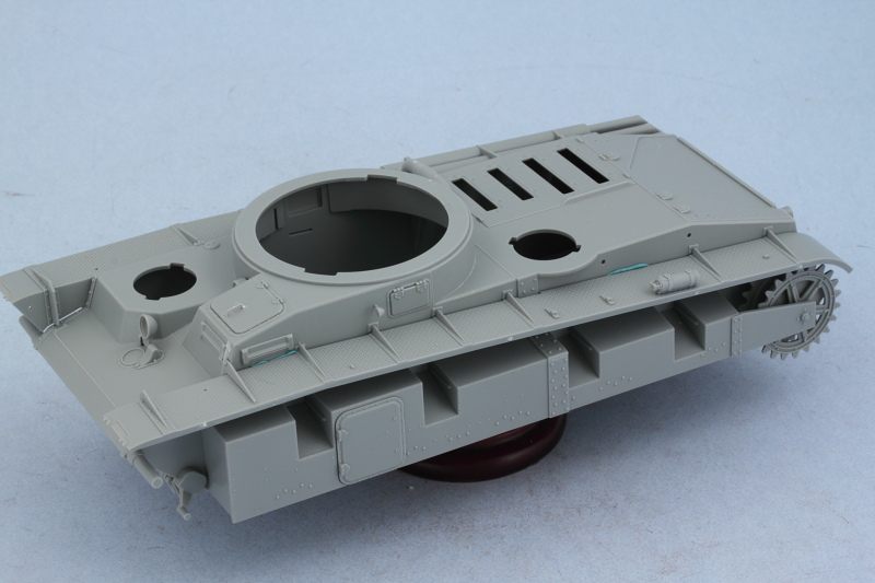
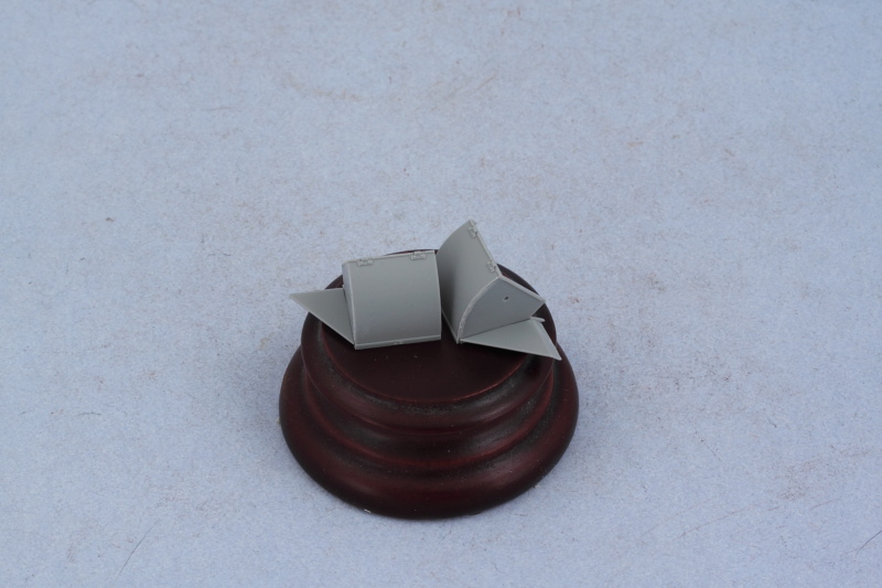
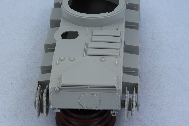
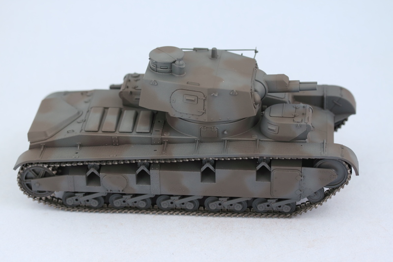
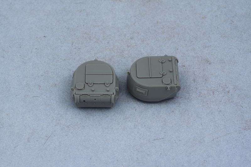
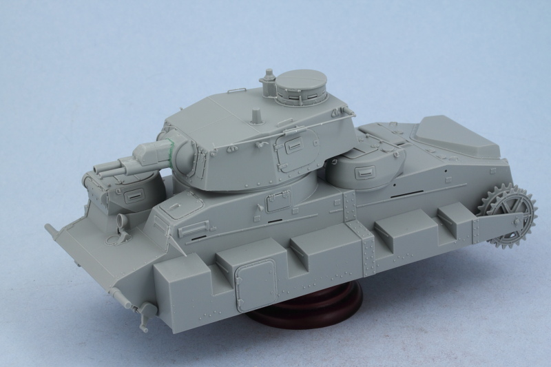
Continuing on with the turrets, Step 11 addresses the twin MG turrets that are cousins of the type seen on the Pz I. I had no desire to display any of the view flaps in the open position so skipped the use of the interior parts and installed them all in the closed position. Curiously DML provides clear armored glass inserts for only the flat side flaps and not the curved flaps...for whatever reason, the curved flaps get an ordinary gray styrene insert. I opted for the hexagonal style of lifting hooks, parts D52, as those are the type commonly seen in the Nr. 3-5 vehicles based on the available reference photos. The MG13s were left off for now and will be installed later after painting. With care during assembly by avoiding getting any glue on part D16, the mantlets can be left movable although their range of movement/positioning is restricted by the turret design.

Image

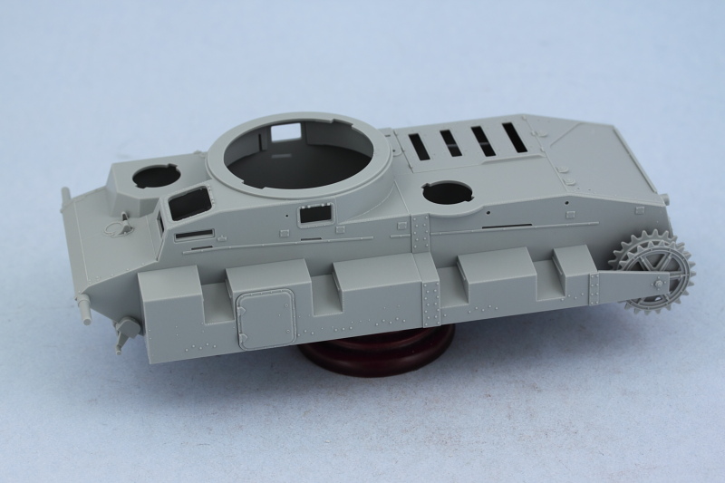
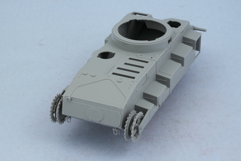
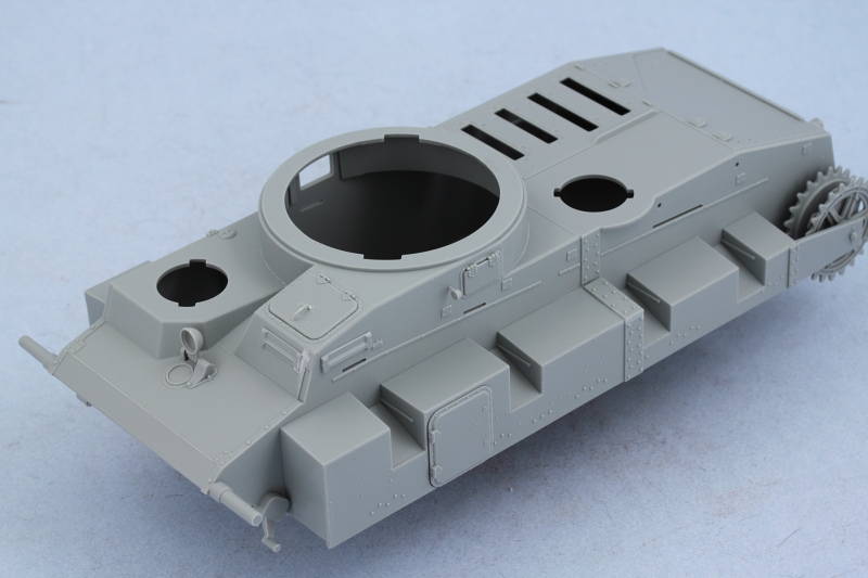
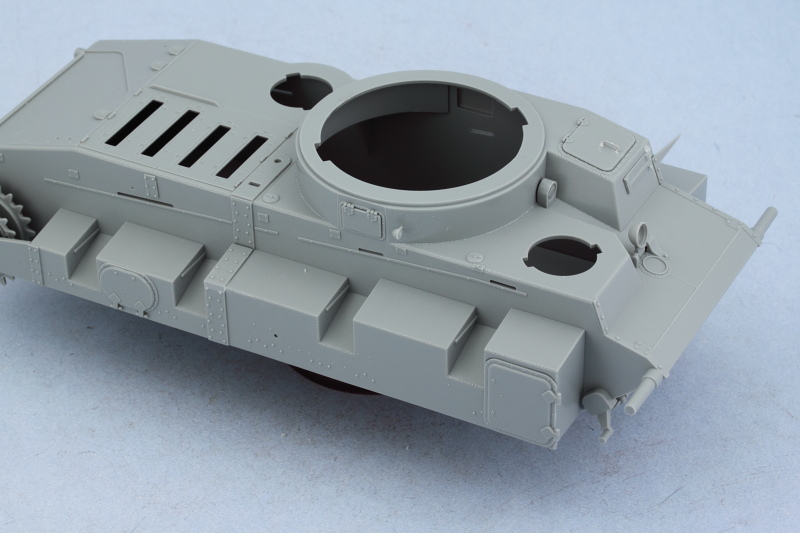
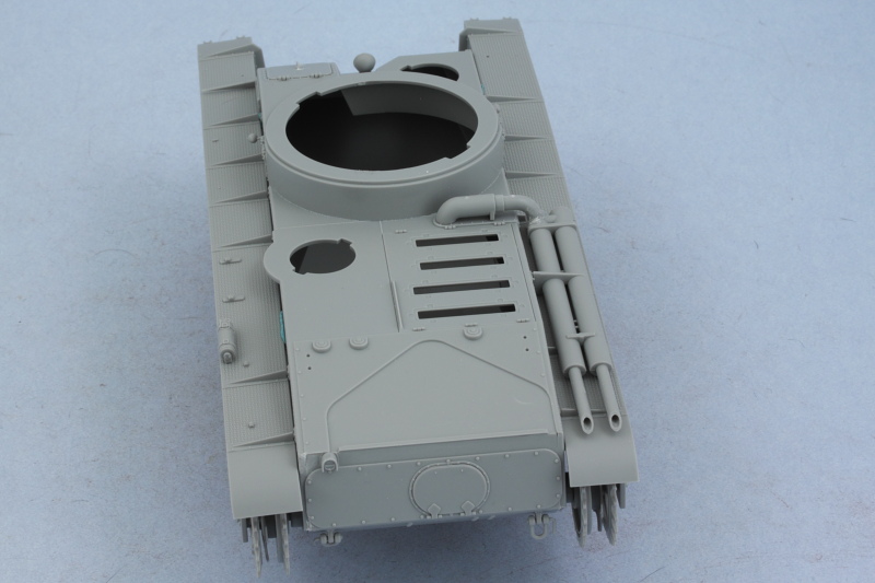
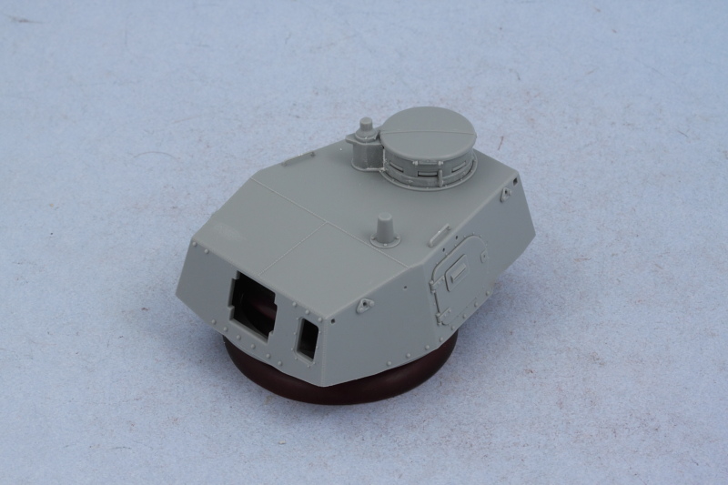
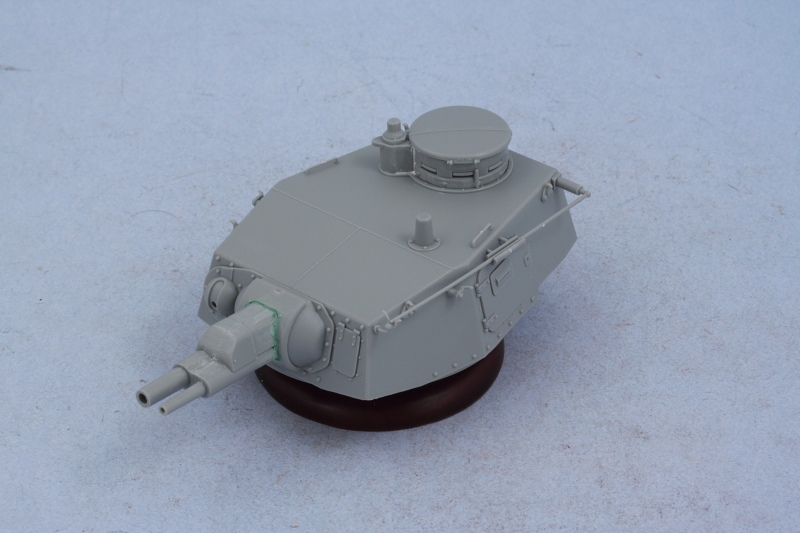
Step 12 begins work on the large main turret and attaches the base of the turret to the top, adds the side hatches, and installs the commander's cupola. The side hatches here also receive ordinary gray styrene vision blocks instead of clear parts and without any kind of interior provided, there's not much point to posing the doors open unless you're going to stuff a figure in there...so mine were closed up. The commander's cupola assembles as a 'stack' of multiple parts and some putty was needed to fill the gap between the cupola and the signal flag port extension that attaches to it.

Image

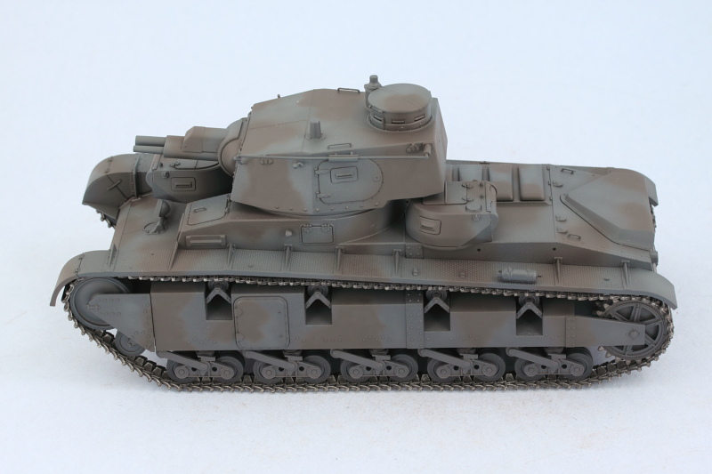
Step 13 adds a lot of delicate detail to the turret side so I bypassed it momentarily to work on Step 14 which assembles and adds the side-by-side main armament. The smaller 3.7cm antitank gun barrel was drilled out slightly to give the barrel a more in-scale diameter and thickness for the muzzle opening. The two guns are paired up in the mantlet as halves, so the resulting join seam needed to be carefully sanded away to create a seamless part. The base of the mantlet is a separate part and shouldn't have a gap, so some Squadron Green putty thinned with liquid glue was used to correct that issue. While the instructions don't indicate it, if you're careful with the assembly and get the alignment of the mantlet base plate and the swivel hub that attaches to it (part B4) correct, it will 'trap' the part sufficiently to allow the main armament to elevate and hold it's position.

Image

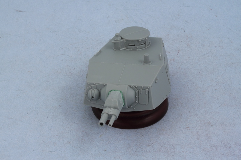
Returning to Step 13, I added the lifting eyes, the antenna and holding tray, and the turret hatch latches. Two different styles of latch are offered and parts B45/44 are the correct style for Nr. 3-5 so those were installed accordingly.

Image

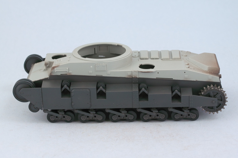
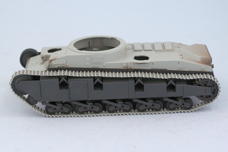
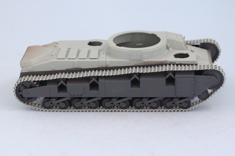
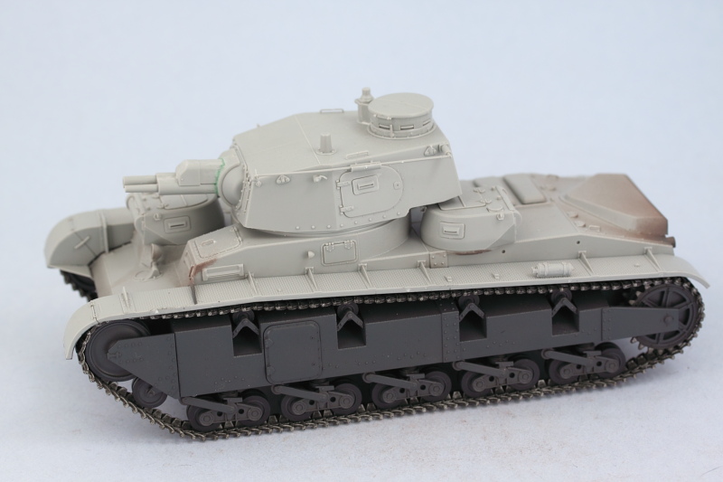
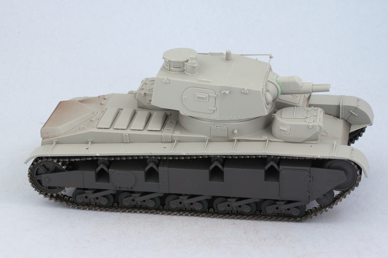
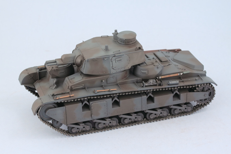
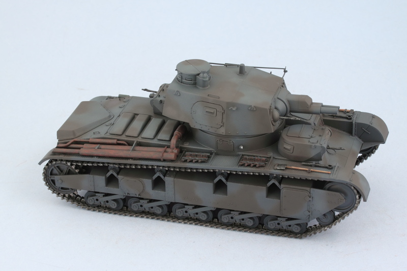
Last but not least, Step 15 adds the turrets to the hull so a sample shot of them in place was called for!

Image

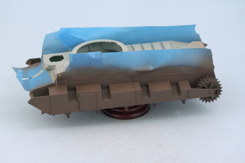
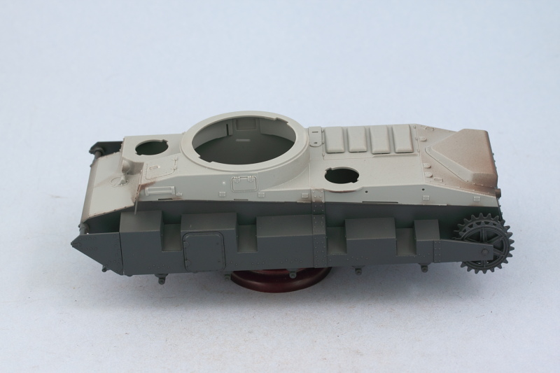
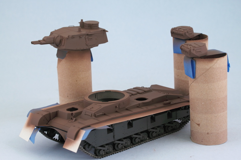
That concludes all the major construction so paint work will be up next!
Bill Plunk
Posts: 1245
Joined: Wed Sep 28, 2022 10:18 pm

WIP 12-30-2012

Post by Bill Plunk »

One of the downsides of the holiday season is that it's also cold season! I've been sidelined with a cold the last few days and that ruled out any possibility of painting, so I made use of the available time to take care of one of the less-glamorous-but-necessary tasks...cleaning up the tracks for this beast.

The kit supplies the individual links on sprues of 40 links with three attachment points per link.

Image

The instructions call for 124 links per side so I removed and cleaned up a total of 250 links just to have a couple handy when the time comes to assemble the track runs. The links aren't handed so I only separated them into two bags in terms of the split of links necessary for each run.

Image

Doing this kind of thing while listening or watching a football game makes the repetition less onerous...and I'm glad to have it out of the way! Hopefully next weekend will afford some time to get things back on track for the paintwork that needs to happen for the build to progress.
Bill Plunk
Posts: 1245
Joined: Wed Sep 28, 2022 10:18 pm

WIP 03-16-2013

Post by Bill Plunk »

Life has a way of getting in the way at times in terms of building models but for the first time in a long time I was able to get back to the bench and make some much-needed progress on this build.

I had done all the major construction with the initial plan of painting everything and then adding the suspension, tracks, and fenders but I decided to go a slightly different route instead. After looking at how the fenders install, I'm going to put in the suspension and tracks and then add the fenders and do the paint work for the vehicle in two stages. The first stage involves the lower hull, so I masked off the glue-line for the fenders so they will have a clean surface to mate up with for installation. I used MM Italian Dark Brown to lay down a primer coat by airbrush.

Image

After primer, the base coat of MM enamel Panzer Schwarzgrau was applied by airbrush. One of the little side lights came off in the process, will add that back later on when it has less of a chance of getting knocked off again. The little sponson extensions that trap the idler were held in place with blue-tack and have not yet been glued in position. Camo pattern and some post-shading on the panzer gray will be done later when the rest of the hull is painted.

Image

At the same time as I worked on the hull, I did all of the suspension components as well including the numerous road wheels. They were primered just like the hull and I airbrushed MM enamel Gunmetal for the rubber portions. Using a draftsman's circle template, the hubs were airbrushed with the Schwarzgrau to round things out.

Image

Next up will be the fun of putting all the suspension components together and making sure it all sits level before tackling the tracks.
Bill Plunk
Posts: 1245
Joined: Wed Sep 28, 2022 10:18 pm

WIP 03-24-2013

Post by Bill Plunk »

Work continued in the latest session on the lower hull and suspension. The design on this vehicle is a bit tricky and Dragon used a modular approach with a separate plate for the trucks to install to with the plate installing into the hull sponsons. The real challenge in this approach is getting all 10 wheels lined up correctly on either side by trapping them between the truck mounts. I made an attempt to leave the wheels able to rotate but found it necessary to glue them in place on their mount pins as the truck halves didn't have enough natural tension to keep them from popping out otherwise. Both sides were assembled and allowed to dry thoroughly before proceeding.

Image

As already mentioned, the suspension on this vehicle is a complex design. After studying things for a bit, I determined the best route was to install the front idlers, tension wheels, and support plates first to ensure I had a straight alignment between them, the drive sprockets, and the return rollers that would install along the top run. The return rollers are similar to the road wheel trucks in that they trap the roller between two mount halves. The installation of the roller mounts into the sponsons must be precise as all four have to align perfectly for the track runs to come. Dragon molded a small step on either side of the sponson openings to help with the positioning and the fit tolerance here is tight. It was necessary to scrape paint with a needle file to get the right fit and the position of the outer half of the mount is the key since it has a small stop in its base to prevent it from sliding in too far on the position step. After I had installed the rollers on both sides, some light touch-up with the panzer gray used earlier tied everything together. I also took the opportunity to create the sprocket teeth wear using some MM non-buffing Metalizer Steel and dry-brushed enamel Burnt Umber since this is the last time it would be easily accessible.

Image

The next step was to assemble the track runs and test them for fit and sag. The instructions call for 124 links per side and that worked out perfectly for the right side but the left needed 1 more link to get things in shape. Each track side consists of 4 parts of 30-35 links that can be separated for painting and weathering off the vehicle. The runs will be allowed to set up thoroughly for 24 hours before moving on to the next phase.

Image

Image
Bill Plunk
Posts: 1245
Joined: Wed Sep 28, 2022 10:18 pm

WIP 03-28-2013

Post by Bill Plunk »

The track saga continues with some more progress to report. After letting the 4 runs per side thoroughly set up for at least 24 hours, I carefully removed them from the suspension for painting. Since the two sides are not identical, it was essential to avoid any mix-ups between them, so I used an old MK track box with a divider and handy post-it note labels to keep things separate. I airbrushed a base coat of MM Burnt Umber as the foundation and let that cure for 24 hours before moving on to the next phase.

Image

The track runs were further detailed by dry-brushing MM enamel Steel with a large round 0 sable brush followed by a light wash of MM enamel Raw Umber to tone down the Steel and tie things together. Once the wash had dried, the track runs were knitted together on both sides and installed.

Image

Image


Next up will be adding the fenders and continuing the paint work for the top side.
Bill Plunk
Posts: 1245
Joined: Wed Sep 28, 2022 10:18 pm

WIP 03-31-2013

Post by Bill Plunk »

First off, Happy Easter to those who observe/celebrate the holiday!

Lots of progress to report so we'll get right to it. First order of business was to install the fenders. I used a combination of regular glue on the tab slots and liquid glue along the edges to get a good and level join. I also reinstalled the little side hull lights that had gotten knocked off earlier. While not visible in the photo, I took advantage of that opportunity to drill out their solid faces with a pin vise to allow for greater detail later on.

Image

Image

Prior to painting, I masked off the lower hull and tracks using a combination of thin strips of sheet styrene inserted under the fenders and blue painter's tape. Primer coat of Italian Dark Brown was applied by airbrush as the foundation. Three cardboard tubes and painter's tape created handles so I could easily paint the three turrets.

Image

Base coat of MM Panzer Schwarzgrau came next.

Image

Base coat highlights were added using an 80/20 mix of Schwarzgrau and Light Gray. Highlights were applied semi-randomly but with the main intent of creating a post-shade effect.

Image

Then came the fun part, applying the disruptive camo pattern suitable for a vehicle in Norway in 1940. I used MM enamel Schokoladenbraun and applied the pattern free-hand.

Image

Image

Paint will get the chance to cure thoroughly over the course of the next week and attention will shift to the remaining equipment and fender details.
Bill Plunk
Posts: 1245
Joined: Wed Sep 28, 2022 10:18 pm

WIP 04-07-2013

Post by Bill Plunk »

Latest round of effort focused on the details for the fenders. The Neubau has a lot of fender space for tools and such but doesn't use the 'normal' type of clamps for them, so I stayed with the kit-supplied clamps and made minor modifications in thinning a couple of the molded-on handles to be more in-scale. Reference pics showed that the crews added two sets of spare tracks to the right hand fender so I used some spare PE brass strip and some Lion Roar hex nuts to create some simple mounts along with two runs of 4 links from the left-over kit supplied tracks. I used a #76 finger drill to open up the pin holes on the first and last link for each spare run for added detail. Last but not least, using the same finger drill, I also opened up the threaded ends on the gun-cleaning rods and used a short length of white rod styrene to simulate the 'male' end of the rod with the cleaning swab.

All the tools were painted using various colors. Metal portions were base coated with MM non-buffing metalizer Gunmetal and lightly dry-brushed with MM Steel. Wood portions were given a base coat of 50/50 MM Dunkelgelb/Light Gray followed by a wash of MM Leather and then dusted with Burnt Umber artist pastels. For the mufflers, I applied a base coat of metalizer Gunmetal, followed by a wash of MM Leather, then stippled MM Rust to create a random pattern. This was followed up with some dry-brushed MM enamel Burnt Umber to blend things back together a bit and tone down the Rust.

Image

Then the tools were installed in place on the vehicle. It's worth noting that the small MG turrets need to be in place before doing this as the front turret in particular can't clear the track tensioning wrench once it's installed. The rear turret also has clearance issues with the jack mount but can still rotate enough in the opposite direction to allow it to be removed. The turret MGs were painted and detailed in the same fashion as the metal tools and glued into place in their respective mounts.

I also used the available time to add some subtle variation to the Schokoladenbraun camo pattern applied last time around. I used MM Italian Dark Brown via airbrush to create some slight lightening and shadows here and there as further prep for the weathering work to come.

Image

Image

Although not shown clearly in the above photos, I also used some regular enamel Silver to paint the interior faces of the small side lights and the large front headlight. Tamiya Clear Red was used for the rear brake light as well to round things out in the detail department.

Next up will be sealing everything and applying the markings.
Post Reply