Meng French FT-17 Light Tank (Rivetted Turret) (2014)
-
Bill Plunk
- Posts: 1245
- Joined: Wed Sep 28, 2022 10:18 pm
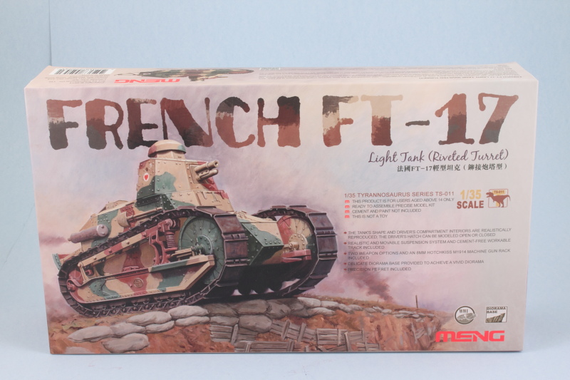
Meng French FT-17 Light Tank (Rivetted Turret) (2014)
Build log for Meng's 1/35 French FT-17 Light Tank (Rivetted Turret), kit# TS-011.
-
Bill Plunk
- Posts: 1245
- Joined: Wed Sep 28, 2022 10:18 pm
WIP 09-21-2014
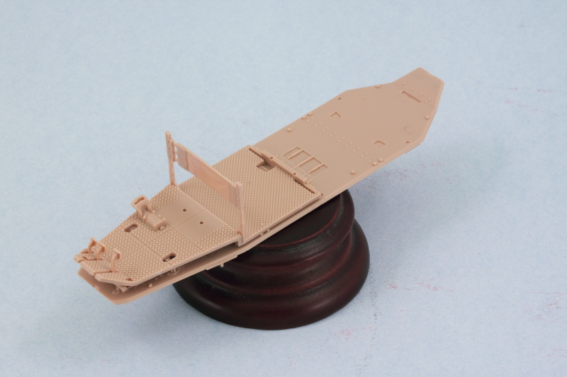
I started work on this little guy with Step 1 which deals with the hull floor plate and various elements of the driver's station and controls. As I'm contemplating painting the interior and leaving the access hatches open for this area, I left off the driver's seat cushion and control levers for the time being.
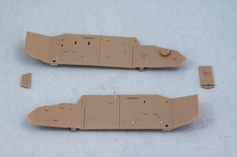
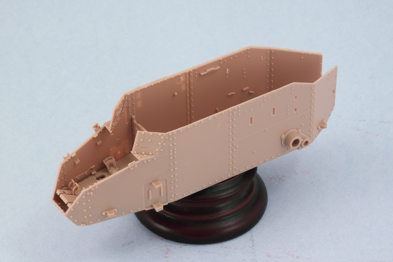
Next I cleaned up the hull sides and the nose and rear plates so I could get a good idea of how the hull would come together. Left side of the hull received the two-gauge instrument panel which was a little challenge to place since there aren't any locater marks or guides for where it should go beyond the one diagram in Step 2.
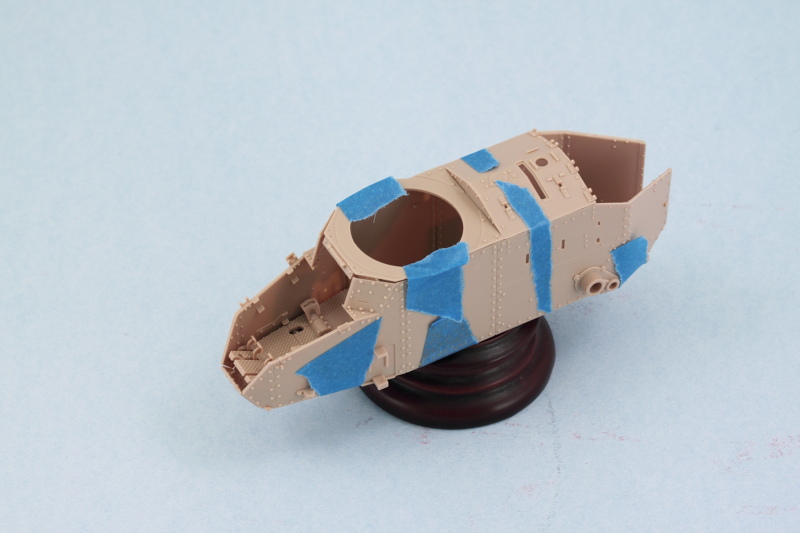
I assembled the hull roof plate as directed in Step 6 and added the angled side armor plates for the driver's view hatch outlined in Step 7. The nose plate, B8, was also installed on the hull floor. A quick check with some strips of masking tape let me mock up the hull and make sure that everything will fit together properly. The slight gap visible at the front of the hull roof is due to the limitations of the tape contact/tension in that area and not a fit flaw in the kit.
Skipping ahead a bit to Step 13, I cleaned up the driver's view hatch and the two access hatches and added their grab handles.
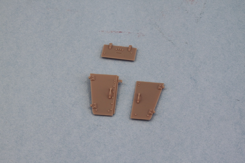
At this point I'm not 100% sure I will go ahead and leave the driver's area hatches open. This particular kit doesn't include any additional detail for the interior past the driver's seat back so I'm rethinking the notion. I may just pose the driver's vision hatch open instead...or just keep things simple and close it all up. Have to see how I feel about it and go from there I guess.
Next I cleaned up the hull sides and the nose and rear plates so I could get a good idea of how the hull would come together. Left side of the hull received the two-gauge instrument panel which was a little challenge to place since there aren't any locater marks or guides for where it should go beyond the one diagram in Step 2.
I assembled the hull roof plate as directed in Step 6 and added the angled side armor plates for the driver's view hatch outlined in Step 7. The nose plate, B8, was also installed on the hull floor. A quick check with some strips of masking tape let me mock up the hull and make sure that everything will fit together properly. The slight gap visible at the front of the hull roof is due to the limitations of the tape contact/tension in that area and not a fit flaw in the kit.
Skipping ahead a bit to Step 13, I cleaned up the driver's view hatch and the two access hatches and added their grab handles.
At this point I'm not 100% sure I will go ahead and leave the driver's area hatches open. This particular kit doesn't include any additional detail for the interior past the driver's seat back so I'm rethinking the notion. I may just pose the driver's vision hatch open instead...or just keep things simple and close it all up. Have to see how I feel about it and go from there I guess.
-
Bill Plunk
- Posts: 1245
- Joined: Wed Sep 28, 2022 10:18 pm
WIP 09-28-2014
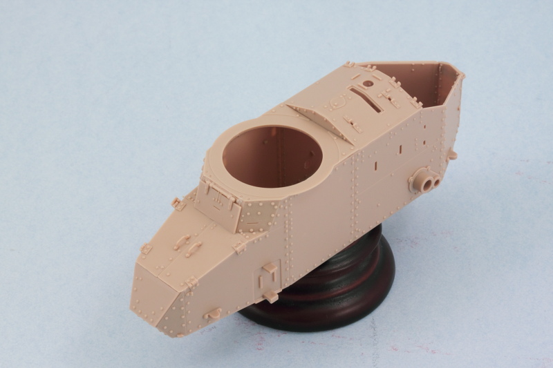
After some back and forth I decided ultimately to go ahead and button up this little guy and not display the driver's hatches open. So with that decided, I set about assembling the hull. Since it's all separate panels, I used regular glue on the hull sides so they could have some stability and then followed that up with careful applications of liquid glue where needed along the bottom edges.
Then I added the roof plate next so I could use it to get the hull sides lined up square and the small driver's area side plates lined up with the view port hatch hinge and the top edges of the roof plate. This all requires some careful use of finger pressure and glue as the areas involved are tiny and rubber bands or clamps can't do the job. Then I added the angled top plate for the nose and the driver's access hatches since all three need to line up just so with each other to avoid issues or gaps. Last but not least, I added the driver's visor in the closed position.
That got a chance to set up nice and solid overnight and attention turned to the engine deck area under Step 6. It's important to note (as the instructions do) that the sledgehammer is trapped in place by the little vent cover, B9, so that means it will have to be detailed in place later on. To help make that easier, I didn't glue the sledgehammer down, just placed it and am allowing B9 to hold it in place for now. In Step 7, the instructions would have you place part B11 and then add the engine bay hatches in Step 14. I found it easier to add them all together at the same time as B11 needs to be lined up very precisely in relation to the hatches for everything to play nice with each other here. This isn't a kit flaw or an engineering issue, quite the contrary...the engineering is very well done for these parts but since the vehicle itself is so small, fractions of a mm do matter in getting everything lined up correctly with all the plates/parts involved.
In preparation for working on the turret, I opted for the 37mm cannon version in Step 15. I assembled the gun as directed and used a drill bit to open up the cannon muzzle a bit more. The molding on the end of my barrel wasn't perfect, so some careful sanding and trimming was needed to get it into shape. I also installed it into the turret faceplate so that its all one module now and ready to go into the turret.
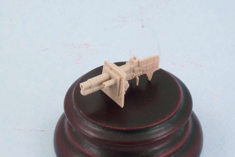
Since the turret assembles as a series of plates onto an octagonal base, that's going to require some careful attention to get all the plates together and lined up between the roof and base, so that will be what's on deck for the next round of effort.
Then I added the roof plate next so I could use it to get the hull sides lined up square and the small driver's area side plates lined up with the view port hatch hinge and the top edges of the roof plate. This all requires some careful use of finger pressure and glue as the areas involved are tiny and rubber bands or clamps can't do the job. Then I added the angled top plate for the nose and the driver's access hatches since all three need to line up just so with each other to avoid issues or gaps. Last but not least, I added the driver's visor in the closed position.
That got a chance to set up nice and solid overnight and attention turned to the engine deck area under Step 6. It's important to note (as the instructions do) that the sledgehammer is trapped in place by the little vent cover, B9, so that means it will have to be detailed in place later on. To help make that easier, I didn't glue the sledgehammer down, just placed it and am allowing B9 to hold it in place for now. In Step 7, the instructions would have you place part B11 and then add the engine bay hatches in Step 14. I found it easier to add them all together at the same time as B11 needs to be lined up very precisely in relation to the hatches for everything to play nice with each other here. This isn't a kit flaw or an engineering issue, quite the contrary...the engineering is very well done for these parts but since the vehicle itself is so small, fractions of a mm do matter in getting everything lined up correctly with all the plates/parts involved.
In preparation for working on the turret, I opted for the 37mm cannon version in Step 15. I assembled the gun as directed and used a drill bit to open up the cannon muzzle a bit more. The molding on the end of my barrel wasn't perfect, so some careful sanding and trimming was needed to get it into shape. I also installed it into the turret faceplate so that its all one module now and ready to go into the turret.
Since the turret assembles as a series of plates onto an octagonal base, that's going to require some careful attention to get all the plates together and lined up between the roof and base, so that will be what's on deck for the next round of effort.
-
Bill Plunk
- Posts: 1245
- Joined: Wed Sep 28, 2022 10:18 pm
WIP 10-03-2014
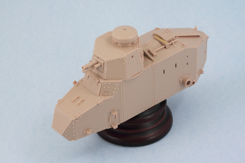
Made some great progress on this little guy in the turret department. Steps 16 and 17 cover the assembly and it's important to note that the base of the turret is an octagonal ring with notches for tabs at the bottoms of each of the plates. You can start wherever you want, but once you commit to the position of the front plate with the gun, you need to place all the other plates as the instructions point out. In anticipation of that, I removed each of the panels from the sprue, cleaned them up, and marked their part number on the inside face so I didn't accidentally place a plate in the wrong spot.
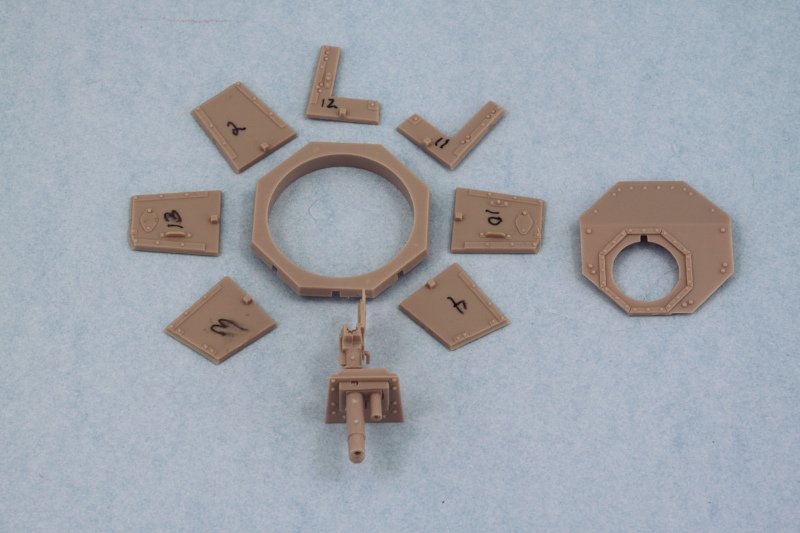
I opted for regular glue on the bases of the plates so they had a good grip, placed the front plate and gun first, then added the plates to either side, and so on until I had all the plates in position. I deliberately did not apply any glue to the areas where the plates met each other though until I was ready to install the turret roof plate. This made it possible for me to use the roof plate to help ensure all the side plates leaned in at the right angle and matched up as needed. I was impressed with the fit/engineering of all these parts...they all lined up nicely and only needed some slight finger pressure in a couple of spots to help the liquid glue grip and seal up the plate joins.
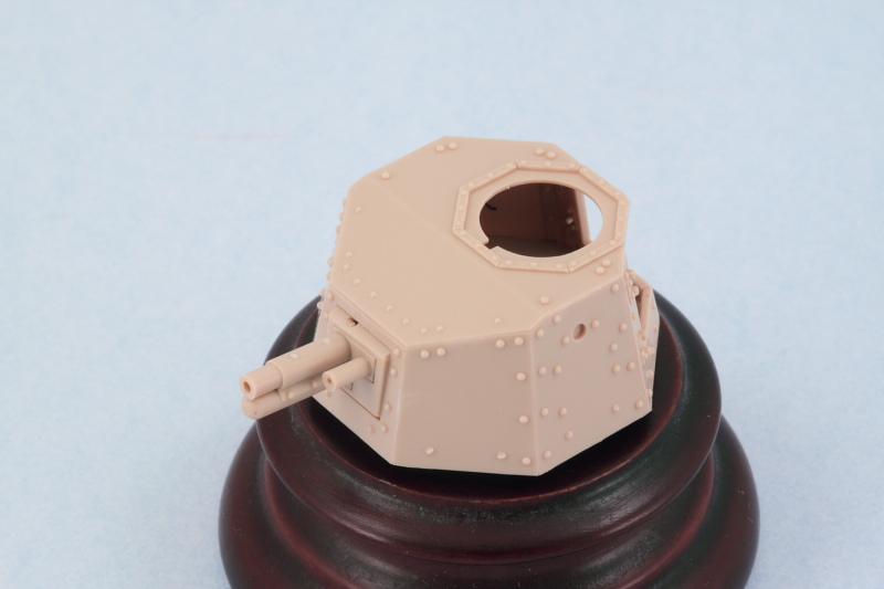
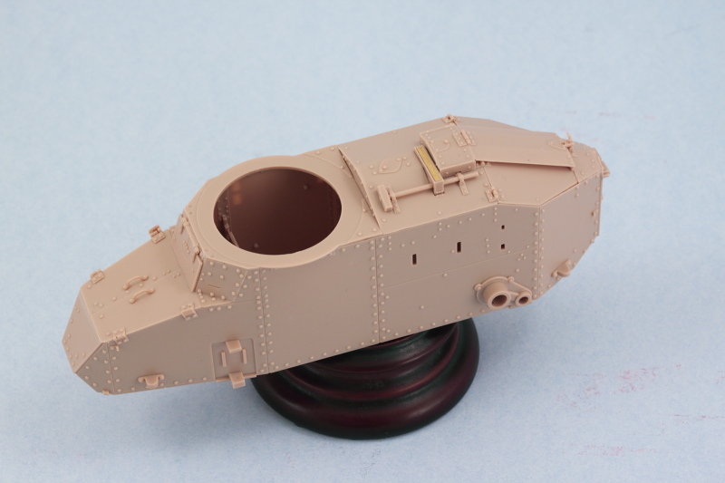
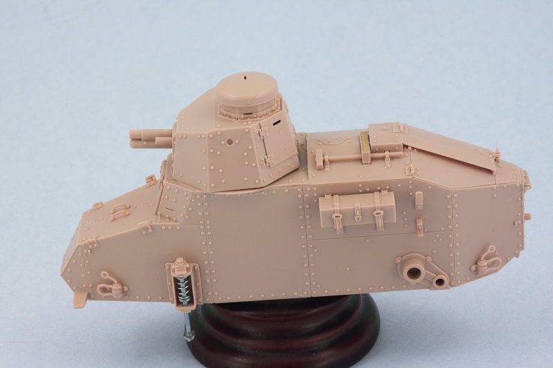
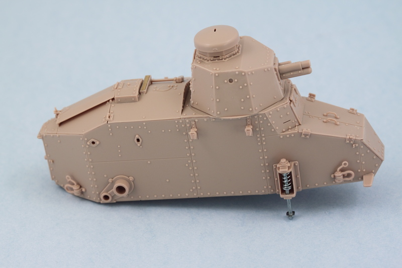
With all the plates in place, I added the rear turret hatches in the closed position. Then the three part cupola came next to round out things for the turret.
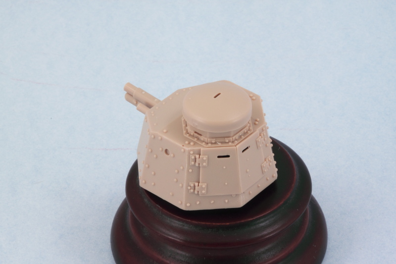
The turret base ring fits snugly into the hull roof opening, a nice friction fit that still allows the turret to rotate, so I'll have to be mindful of that when painting to ensure it stays that way.
Next up will be tackling the suspension components, lots of small parts there so will take my time there as well.
I opted for regular glue on the bases of the plates so they had a good grip, placed the front plate and gun first, then added the plates to either side, and so on until I had all the plates in position. I deliberately did not apply any glue to the areas where the plates met each other though until I was ready to install the turret roof plate. This made it possible for me to use the roof plate to help ensure all the side plates leaned in at the right angle and matched up as needed. I was impressed with the fit/engineering of all these parts...they all lined up nicely and only needed some slight finger pressure in a couple of spots to help the liquid glue grip and seal up the plate joins.
With all the plates in place, I added the rear turret hatches in the closed position. Then the three part cupola came next to round out things for the turret.
The turret base ring fits snugly into the hull roof opening, a nice friction fit that still allows the turret to rotate, so I'll have to be mindful of that when painting to ensure it stays that way.
Next up will be tackling the suspension components, lots of small parts there so will take my time there as well.
-
Bill Plunk
- Posts: 1245
- Joined: Wed Sep 28, 2022 10:18 pm
WIP 10-08-2014
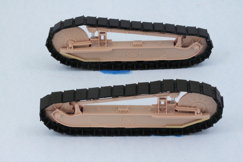
Made some more progress on the little FT-17, this time in the suspension department. I decided to build up the suspension units one side at a time since the elements that you construct in Step 8 are 'handed' between the left and right side and I didn't want to cause any confusion there. I started with the A and B components needed for the left side and also assembled the return roller frame. Lots of care is needed when gluing the frame halves together so that the rollers remain free to rotate. Adding the metal pin and frame supports at the front is also a little challenging but works out in the end with a little patience. When assembling the road wheel elements, I found it easiest to assemble the frame halves and wheels together first, then add the top support arm portion before the glue had set up. This way you could flex the tops open to accept the pins without having the whole thing come apart in the process. The biggest time-consuming element in this step is cleaning up the two sprue connection points per road wheel and return roller as they have very delicate rims that intersect with the connection points.
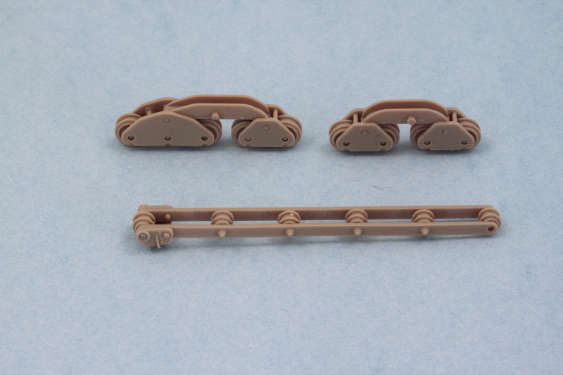
Step 9 assembles the full suspension unit using the components from the previous step. It's possible to assemble it and leave the suspension fully workable if you use the top part of the unit to help hold the sides together. Again, a very tricky assembly process that will leave you wishing you had another hand to help out but the end result produces a very nicely detailed assembly. Once the top and sides were firmly together, I added the support base for the return roller frame and used the kit-supplied steel spring and some CA glue to ensure it sat at the right height and angle to match up with the large idler.
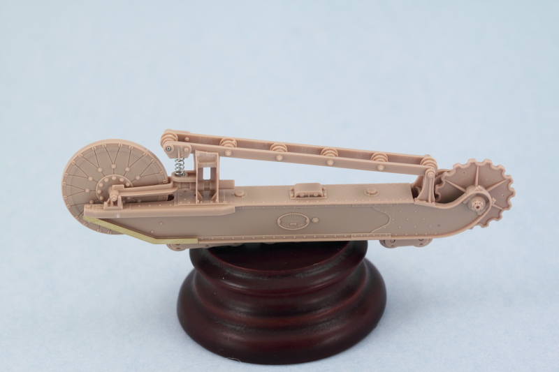
Once I'd figured out the little tricks and traps by doing the first unit, the second one for the right side took only half as long to pull it together.
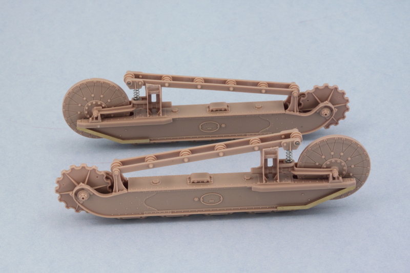
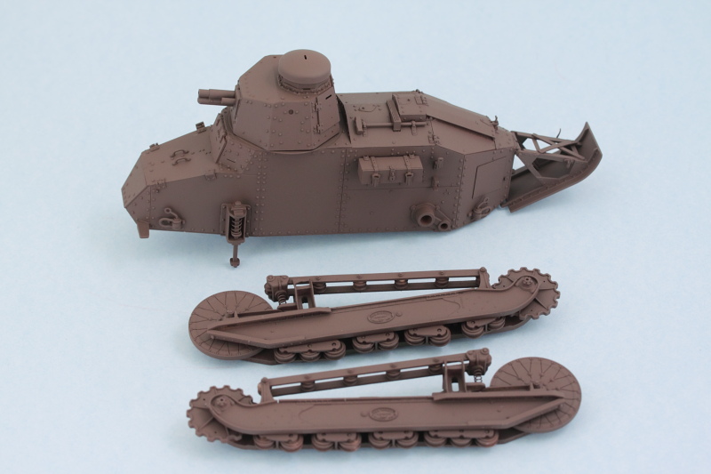
Given how complex this all is and how the suspension relates to the hull, I'm seriously considering leaving them separate for painting to make it easier to get everything covered and also make life simpler in terms of applying a camo pattern. Next up are the exterior details for the hull!
Step 9 assembles the full suspension unit using the components from the previous step. It's possible to assemble it and leave the suspension fully workable if you use the top part of the unit to help hold the sides together. Again, a very tricky assembly process that will leave you wishing you had another hand to help out but the end result produces a very nicely detailed assembly. Once the top and sides were firmly together, I added the support base for the return roller frame and used the kit-supplied steel spring and some CA glue to ensure it sat at the right height and angle to match up with the large idler.
Once I'd figured out the little tricks and traps by doing the first unit, the second one for the right side took only half as long to pull it together.
Given how complex this all is and how the suspension relates to the hull, I'm seriously considering leaving them separate for painting to make it easier to get everything covered and also make life simpler in terms of applying a camo pattern. Next up are the exterior details for the hull!
-
Bill Plunk
- Posts: 1245
- Joined: Wed Sep 28, 2022 10:18 pm
WIP 10-11-2014
Returning to the hull details, I went all the way back to Step 3 and added the details required for the left side of the hull. The kit includes a metal strut and spring for the front part of the suspension and the key to getting this in at the right height is the spring itself and the 'cap' styrene part that sits on top, D11. D11 doesn't sit snugly on top of the strut, so I glued the strut and spring into the housing with CA first and then added D11 to the top after to ensure it lined up correctly with the suspension module and wouldn't cause any fit issues along the way. Tow hooks and large box and rack were also added to round things out.
Process was repeated for the right side in Step 5 but I left off the exhaust muffler for the time being as that will be detailed and installed after painting.
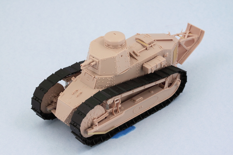
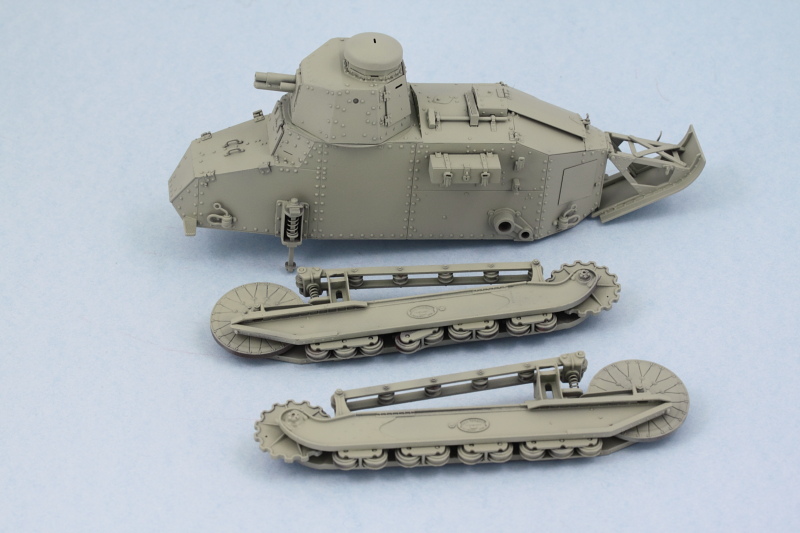
And just to be sure that 'stumpy' here would sit properly with the suspension modules in place, a dry-fit was in order! The test fit shows that when the time comes to glue the modules in place I'm going to have to be a little careful that they sit level as there's a slight tendency for the top to want to bow in slightly since there really isn't anything on the top side to prevent that by way of connection points.
The next item of interest were the tracks which are dealt with in Step 12. The kit provides click-able individual tracks that will produce workable tracks of 32 links per side. I found in the assembly process though that I had to keep a sharp eye out for tiny amounts of flash around the hinge points as if those weren't caught the links would fit together almost rigidly or require too much force that could snap off the small pins. Fortunately the kit provides plenty of extra links so it wasn't a huge deal when a couple got sacrificed in this learning step.
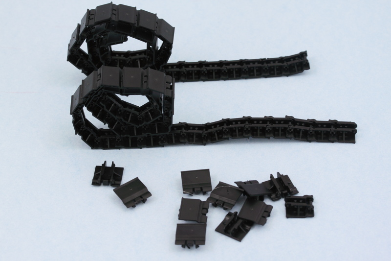
A quick test fit with the suspension modules showed everything playing nice and 32 links working out perfectly. Connecting up the ends of the runs once the tracks have been painted and weathered may be a little challenging...I may just remove one or both of the pins on those final links and just rely on gluing the links together to secure the runs, have to see when the time comes.
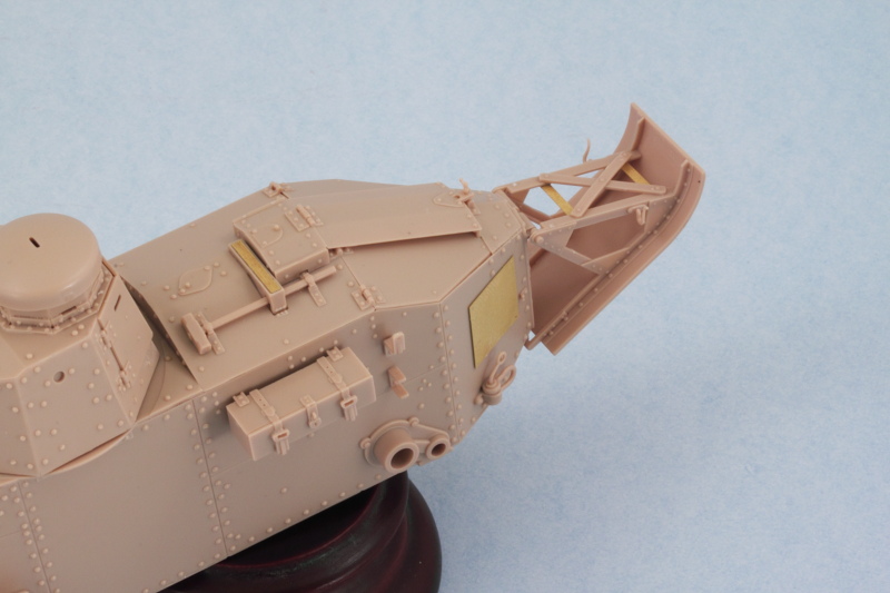
The last remaining area needing attention was the rear hull and the un-ditching tail covered in Step 11. I'm not 100% sure, but I think the PE placards (parts W5) should be placed only if you're doing the American WW1 version of this kit so be mindful of that as the instructions don't make any kind of distinction there. Since I am doing the American version, these were installed with Gator Grip glue so I could have some work time to get them properly positioned/straight relative to the areas they install into. The folded up tarp that installs over the X brace on the tail is left off for now and will be added after painting.
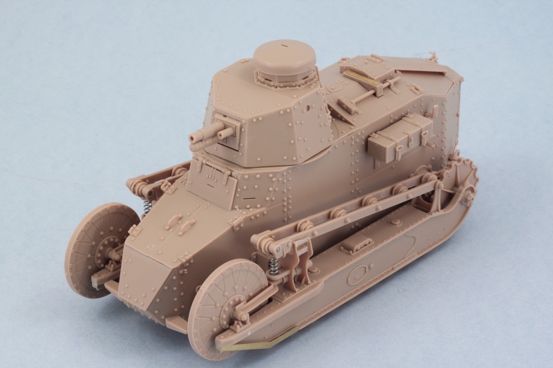
Just to satisfy my curiosity, I did a full mock-up with the suspension elements and tracks and I'm now 100% convinced that painting the suspension separately and installing after is the right way to go on this little guy.
Process was repeated for the right side in Step 5 but I left off the exhaust muffler for the time being as that will be detailed and installed after painting.
And just to be sure that 'stumpy' here would sit properly with the suspension modules in place, a dry-fit was in order! The test fit shows that when the time comes to glue the modules in place I'm going to have to be a little careful that they sit level as there's a slight tendency for the top to want to bow in slightly since there really isn't anything on the top side to prevent that by way of connection points.
The next item of interest were the tracks which are dealt with in Step 12. The kit provides click-able individual tracks that will produce workable tracks of 32 links per side. I found in the assembly process though that I had to keep a sharp eye out for tiny amounts of flash around the hinge points as if those weren't caught the links would fit together almost rigidly or require too much force that could snap off the small pins. Fortunately the kit provides plenty of extra links so it wasn't a huge deal when a couple got sacrificed in this learning step.
A quick test fit with the suspension modules showed everything playing nice and 32 links working out perfectly. Connecting up the ends of the runs once the tracks have been painted and weathered may be a little challenging...I may just remove one or both of the pins on those final links and just rely on gluing the links together to secure the runs, have to see when the time comes.
The last remaining area needing attention was the rear hull and the un-ditching tail covered in Step 11. I'm not 100% sure, but I think the PE placards (parts W5) should be placed only if you're doing the American WW1 version of this kit so be mindful of that as the instructions don't make any kind of distinction there. Since I am doing the American version, these were installed with Gator Grip glue so I could have some work time to get them properly positioned/straight relative to the areas they install into. The folded up tarp that installs over the X brace on the tail is left off for now and will be added after painting.
Just to satisfy my curiosity, I did a full mock-up with the suspension elements and tracks and I'm now 100% convinced that painting the suspension separately and installing after is the right way to go on this little guy.
-
Bill Plunk
- Posts: 1245
- Joined: Wed Sep 28, 2022 10:18 pm
WIP 10-15-2014
I've started in on the painting process and the first order of business was laying down a primer coat of Testors Model Master enamel Italian Dark Brown via airbrush.
I let that set up overnight and then, since I'm applying a three tone camo and the yellow part of the pattern seems to be the most dominant, I applied the yellow portion as a base coat to work off of. I used a 50-50 mix of MM enamel Dunkelgelb/Light Gray as it will not doubt darken during the weathering process.
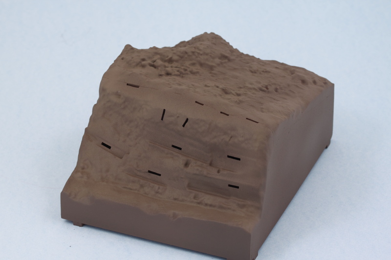
This will get the chance to set up just like the primer as I don't want to take any chances with paint lifting when I mask off the areas for the brown and green areas of the scheme. In the meantime, I decided to give the kit-included base a try. It assembles pretty easily and has a nice cross brace at the bottom that helps hold everything together and give it some rigidity. I did have to employ small amounts of putty in a couple of spots on some of the joins and of course sanding was called for to smooth everything down on all four sides but nothing major.
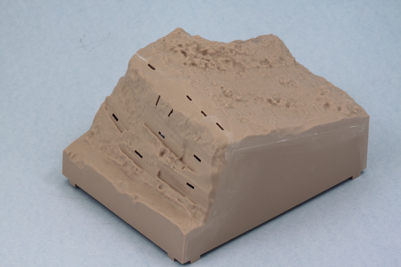
Since I had the airbrush out, I decided to also paint the base. A primer coat of Italian Dark Brown came first, then some highlights using MM enamel Afrikabraun, and an overall filter/mist coat of MM enamel Raw Sienna. It's a little hard for the camera to pick up all the subtleties but it produced a nice starting point to work from that will get further refinement with pigments and dry brushing later on. I will admit to a sudden craving for chocolate cake though...can't imagine why!
That's where things stand at the moment, next up of course will be getting that camo pattern on the vehicle and then finalizing the suspension installation.
I let that set up overnight and then, since I'm applying a three tone camo and the yellow part of the pattern seems to be the most dominant, I applied the yellow portion as a base coat to work off of. I used a 50-50 mix of MM enamel Dunkelgelb/Light Gray as it will not doubt darken during the weathering process.
This will get the chance to set up just like the primer as I don't want to take any chances with paint lifting when I mask off the areas for the brown and green areas of the scheme. In the meantime, I decided to give the kit-included base a try. It assembles pretty easily and has a nice cross brace at the bottom that helps hold everything together and give it some rigidity. I did have to employ small amounts of putty in a couple of spots on some of the joins and of course sanding was called for to smooth everything down on all four sides but nothing major.
Since I had the airbrush out, I decided to also paint the base. A primer coat of Italian Dark Brown came first, then some highlights using MM enamel Afrikabraun, and an overall filter/mist coat of MM enamel Raw Sienna. It's a little hard for the camera to pick up all the subtleties but it produced a nice starting point to work from that will get further refinement with pigments and dry brushing later on. I will admit to a sudden craving for chocolate cake though...can't imagine why!
That's where things stand at the moment, next up of course will be getting that camo pattern on the vehicle and then finalizing the suspension installation.
-
Bill Plunk
- Posts: 1245
- Joined: Wed Sep 28, 2022 10:18 pm
WIP 10-16-2014
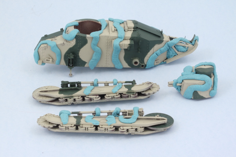
First stage in applying the camo pattern is complete! I'm using the kit's finishing guide for an American tank at Verdun in October 1918 that sports a hard-edged three-tone scheme, so the first order of business was marking out the green areas. I used some 'worms' of poster blue tack putty rolled out and pressed down with a wooden toothpick to create the masks.
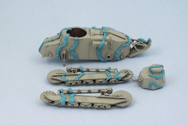
Some Model Master enamel Khaki was airbrushed at low pressure using a fine detail tip. After sitting for a couple of hours to touch dry, I removed the blue-tack to see how it turned out.
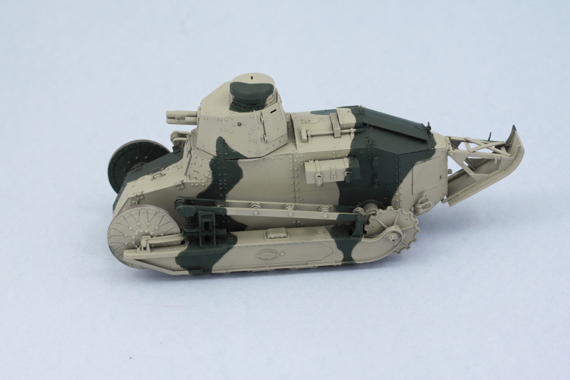
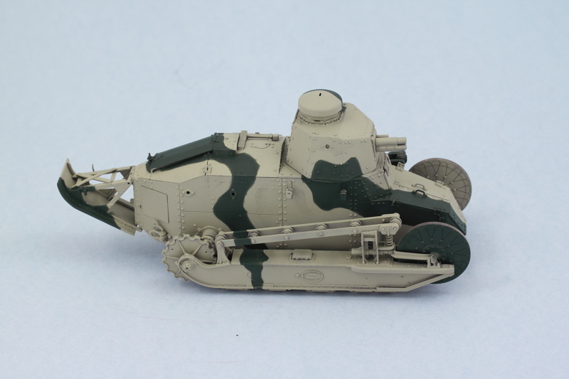
So far, so good, just some tiny areas that might need touch-up later on. Next up will be the red-brown portion.
Some Model Master enamel Khaki was airbrushed at low pressure using a fine detail tip. After sitting for a couple of hours to touch dry, I removed the blue-tack to see how it turned out.
So far, so good, just some tiny areas that might need touch-up later on. Next up will be the red-brown portion.
-
Bill Plunk
- Posts: 1245
- Joined: Wed Sep 28, 2022 10:18 pm
WIP 10-17-2014
Got the rest of the camo pattern on today with the red-brown portions. Same drill as with the green, I used the blue-tack approach to mask off the appropriate areas first.
Out with the airbrush and a mix of 50-50 MM enamel Military Brown and Leather did the trick in no time.

After doing some light touch-ups here and there with the base coat, I sprayed a mist/filter coat of heavily thinned base coat color to tie the scheme all together and fade the scheme a bit.
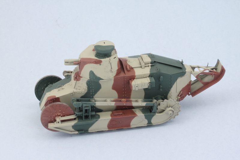
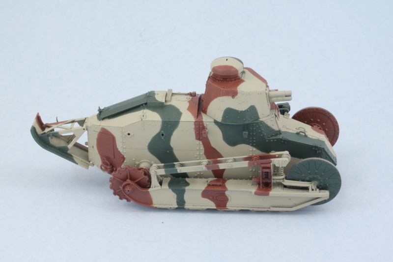
Once the tracks are on it will help break up the pattern some as well and provide some additional visual contrast.
Out with the airbrush and a mix of 50-50 MM enamel Military Brown and Leather did the trick in no time.
After doing some light touch-ups here and there with the base coat, I sprayed a mist/filter coat of heavily thinned base coat color to tie the scheme all together and fade the scheme a bit.
Once the tracks are on it will help break up the pattern some as well and provide some additional visual contrast.
-
Bill Plunk
- Posts: 1245
- Joined: Wed Sep 28, 2022 10:18 pm
WIP 10-18-2014
Just a quick little update albeit an important one. Tracks received their base coat treatment by airbrushing some MM enamel Burnt Umber over the black plastic and will get some additional detailing/weathering attention later on. That doesn't mean they aren't still useful as it was time to go ahead and permanently fix the suspension elements in place to the hull. It was necessary to scrape some paint that had accumulated inside the drive sprocket and final drive mount holes as well as the mount pins themselves as the fit was too tight otherwise...something I had thought to prevent by masking those areas off with blue tack but forgot to do until it was too late. Liquid glue did the trick for those areas along with some CA for the metal struts at the front of the hull. The track runs were dry fit once more to ensure I had a level set top and bottom for the suspensions on both sides.
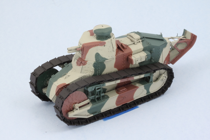
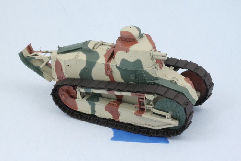
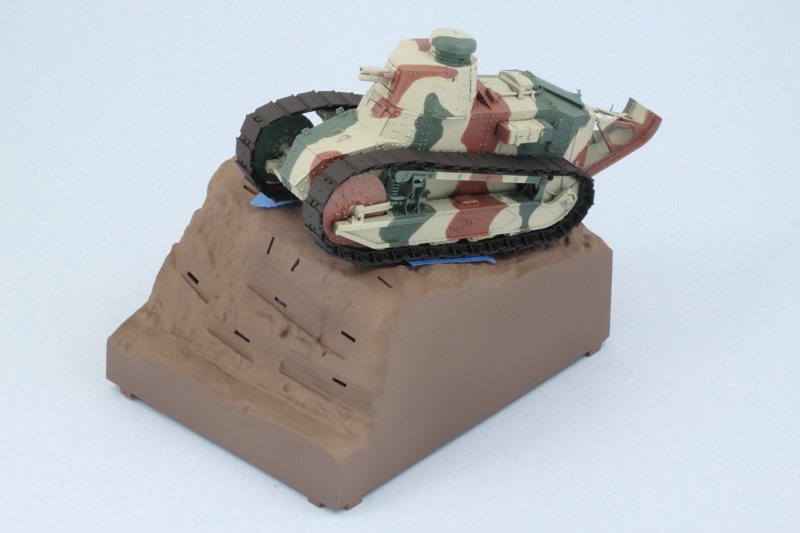
As you can see, having the tracks on totally changes the visual perception of the camo pattern as well, so that works out nicely. Just for fun, I also checked to see how it would look on the kit's dio base.
I'll let the suspension set up nice and solid before the next steps deal with the remaining details prior to getting the weathering process started.