Dragon Pzkpfw VI Ausf. E Sdkfz 181 Tiger I Late Production 3-in-1 (2013)
-
Bill Plunk
- Posts: 1245
- Joined: Wed Sep 28, 2022 10:18 pm
Dragon Pzkpfw VI Ausf. E Sdkfz 181 Tiger I Late Production 3-in-1 (2013)
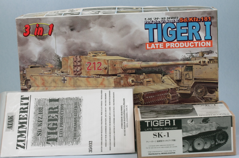
Build log for Dragon's kit #6253 Tiger I Late 3-in-1 in combination with Atak zimmerit and MK workable tracks.
-
Bill Plunk
- Posts: 1245
- Joined: Wed Sep 28, 2022 10:18 pm
WIP 09-29-2013
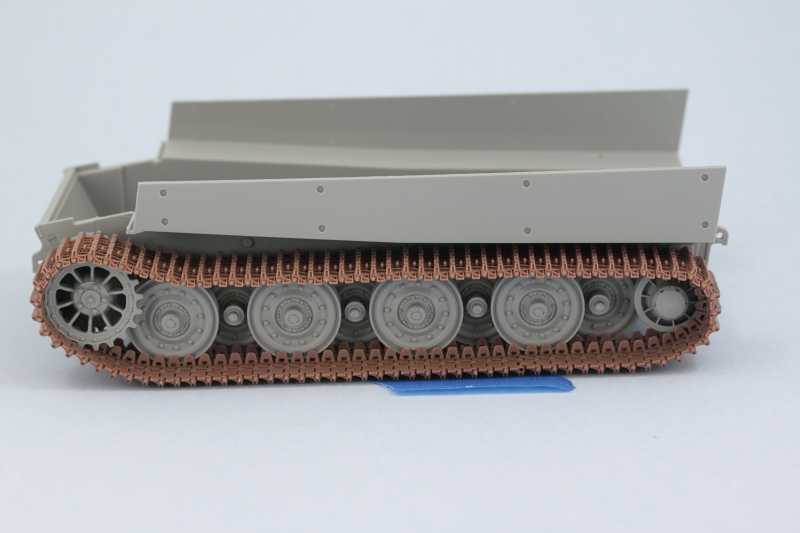
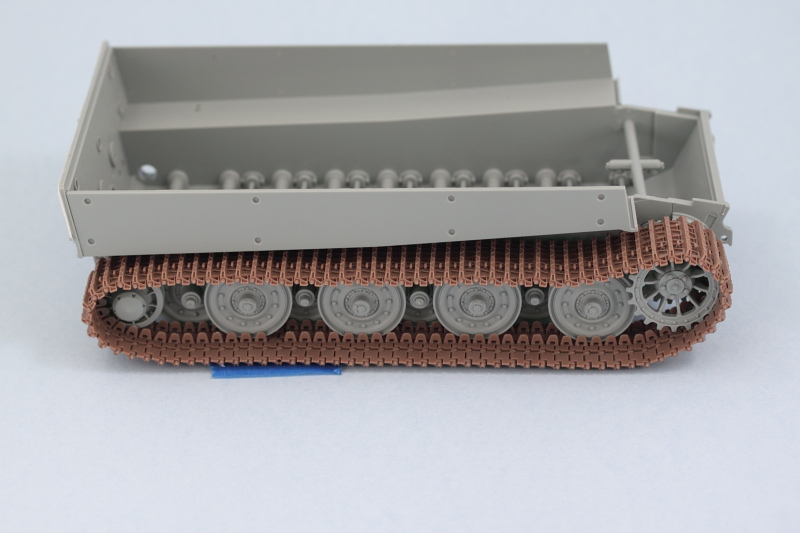
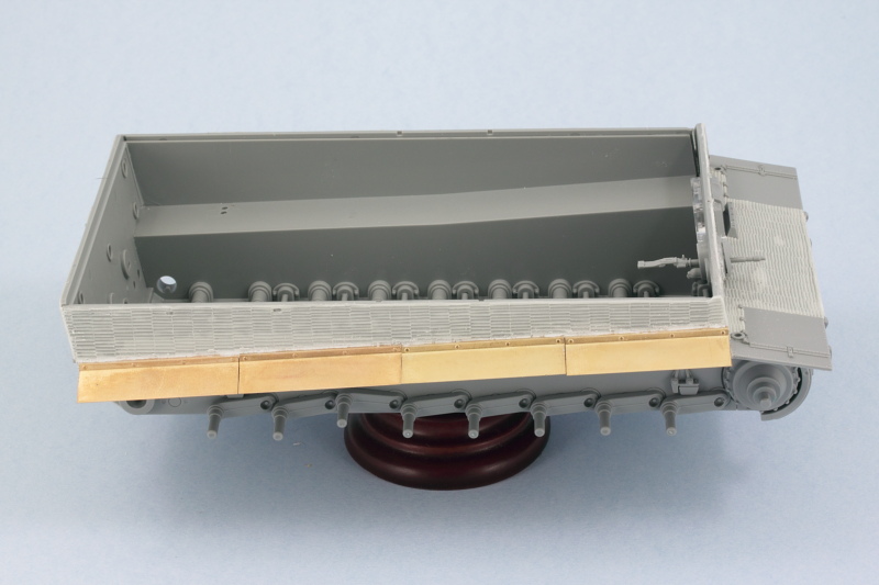
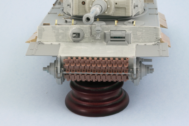
Off and rolling with the usual bane of German tank models, the road wheels! Following the instructions in Steps 1 and 3, the road wheels, sprockets, and idlers were assembled. I opted for the G5 style of wheel appropriate to a standard Late Tiger I as well as the small idler wheels consisting of parts B2-B3 as those are the correct type vs. the larger idler wheel option of G8-G7. I also assembled a short run of 10 of the MK workable links to ensure the sprockets would fit and were spaced properly as well as to test the fit of the paired road wheels.
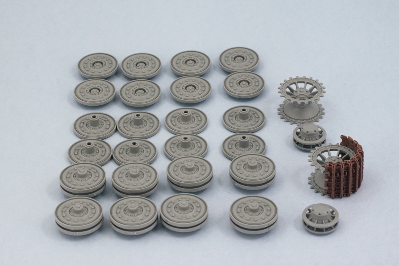
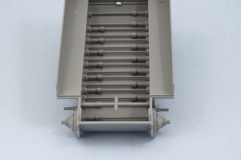
Step 2 involves the installation of the workable torsion bar suspension, so the first order of business was removing the 16 bars from the sprue and cleaning up their three attachment points.

The bars were installed with glue used only on the square ends of the bars to allow them to remain workable. The road wheels were used to ensure the bars and suspension arms sat at the right height with no floaters and the glue allowed to set up.
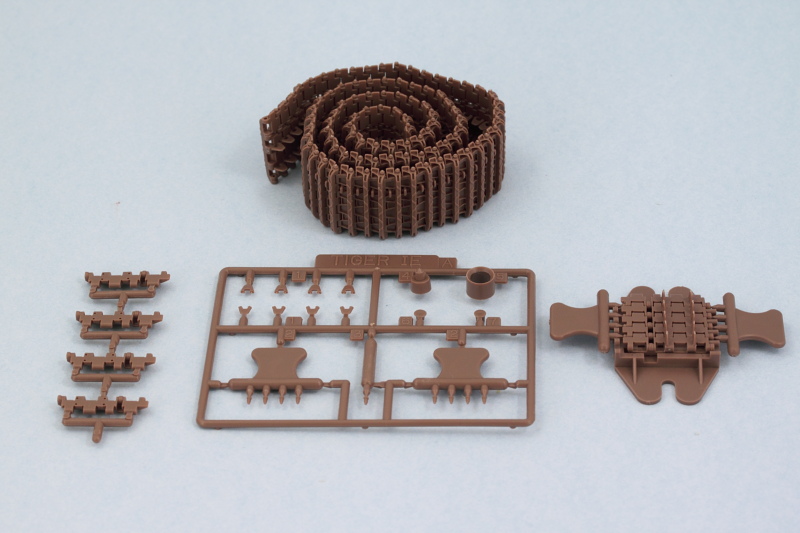
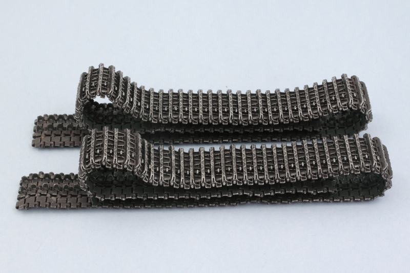
Sunday's are the perfect days for working on tracks as I've found that football games make for great background noise and help break up the tedium of track assembly. Today had some good games on and I had the house to myself, so I started in on the MK workables. The set provides a jig for assembling 5 links at a time and the guide horns are separate. Both the MK instructions and the Dragon instructions call for 95 links for the full track run, but that works with the larger idler...the smaller idler doesn't need as many. I initially assembled 90 links and then a test fit revealed that another 3 were needed for 93 total on the left side. The right side may need one more due to the offset of the torsion bar system but I won't be sure until I build that track run next.
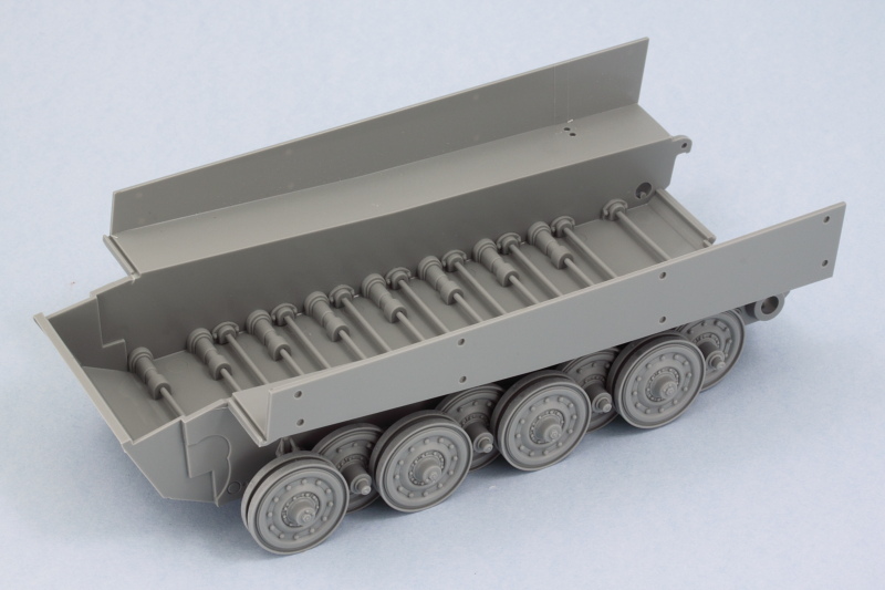
Test fit of the first track run with the movable idler and the sprocket held in place with blue tack showed everything playing nice so far.
Next will be finishing up the 2nd track and beginning work on the rest of the lower hull.
Step 2 involves the installation of the workable torsion bar suspension, so the first order of business was removing the 16 bars from the sprue and cleaning up their three attachment points.
The bars were installed with glue used only on the square ends of the bars to allow them to remain workable. The road wheels were used to ensure the bars and suspension arms sat at the right height with no floaters and the glue allowed to set up.
Sunday's are the perfect days for working on tracks as I've found that football games make for great background noise and help break up the tedium of track assembly. Today had some good games on and I had the house to myself, so I started in on the MK workables. The set provides a jig for assembling 5 links at a time and the guide horns are separate. Both the MK instructions and the Dragon instructions call for 95 links for the full track run, but that works with the larger idler...the smaller idler doesn't need as many. I initially assembled 90 links and then a test fit revealed that another 3 were needed for 93 total on the left side. The right side may need one more due to the offset of the torsion bar system but I won't be sure until I build that track run next.
Test fit of the first track run with the movable idler and the sprocket held in place with blue tack showed everything playing nice so far.
Next will be finishing up the 2nd track and beginning work on the rest of the lower hull.
-
Bill Plunk
- Posts: 1245
- Joined: Wed Sep 28, 2022 10:18 pm
WIP 10-06-2013
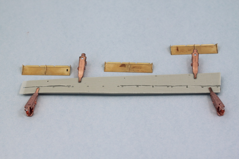
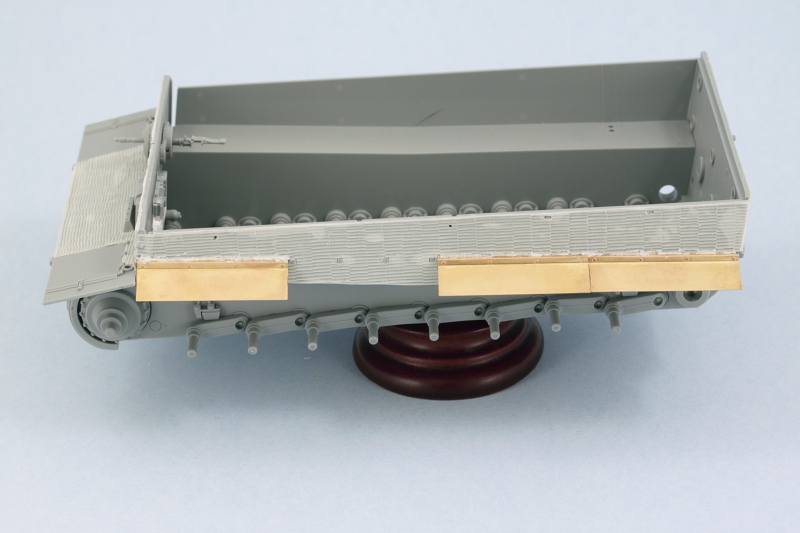
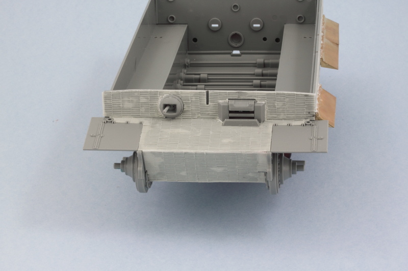
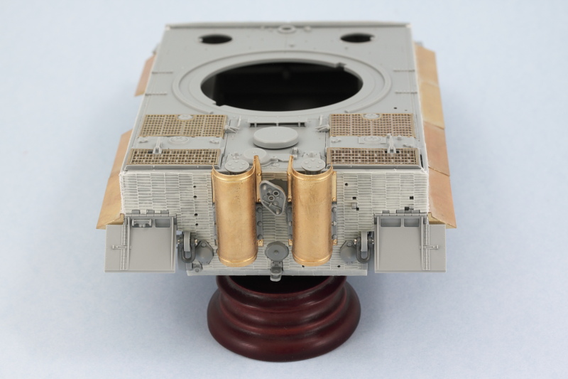
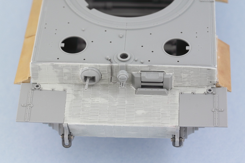
Another weekend means another update! Work continued on the Tiger with attention given to the rear hull plate. The kit part received the corresponding Atak zim panels using a combination of Gator Grip glue to position them and then running liquid glue under the panels to tack down the edges and ensure the panels bonded to the part underneath.
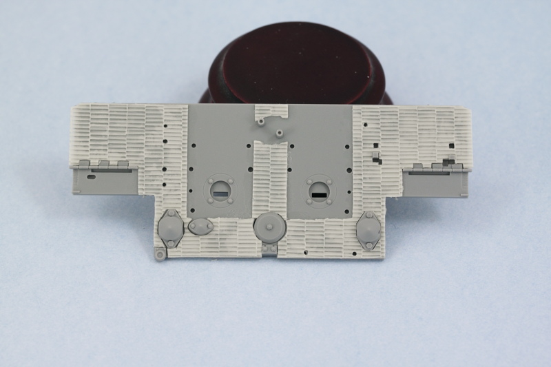
Dragon deliberately molded the hull with a slight warp in the hull tub as a design intended to allow for a snug fit with the plates. The rear plate is big enough and strong enough to force the hull sides into the proper alignment using just regular glue. Once the plate was in place the lower-most zim panel was added around the base of the tow hitch to round things out.
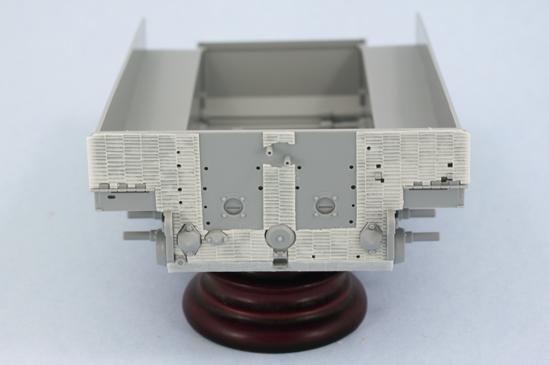
The front of the hull however needs a little help to overcome the warp, so a piece of sprue was cut down to the necessary size and glued in place to brace the hull and help it hold its shape better.
I dry-fitted the glacis plate along with the hull roof and the front plate of the fighting compartment. This not only ensured that the bracing length of sprue was providing the right level of correction, it also ensured that the brace held its position correctly while the glue set.
Then I sat down to deal with the remaining 2nd track. 2 football games and 93 links later, the second one was completed.
Next up will be more work on the hull side panels and other similar details.
Dragon deliberately molded the hull with a slight warp in the hull tub as a design intended to allow for a snug fit with the plates. The rear plate is big enough and strong enough to force the hull sides into the proper alignment using just regular glue. Once the plate was in place the lower-most zim panel was added around the base of the tow hitch to round things out.
The front of the hull however needs a little help to overcome the warp, so a piece of sprue was cut down to the necessary size and glued in place to brace the hull and help it hold its shape better.
I dry-fitted the glacis plate along with the hull roof and the front plate of the fighting compartment. This not only ensured that the bracing length of sprue was providing the right level of correction, it also ensured that the brace held its position correctly while the glue set.
Then I sat down to deal with the remaining 2nd track. 2 football games and 93 links later, the second one was completed.
Next up will be more work on the hull side panels and other similar details.
-
Bill Plunk
- Posts: 1245
- Joined: Wed Sep 28, 2022 10:18 pm
WIP 10-13-2013
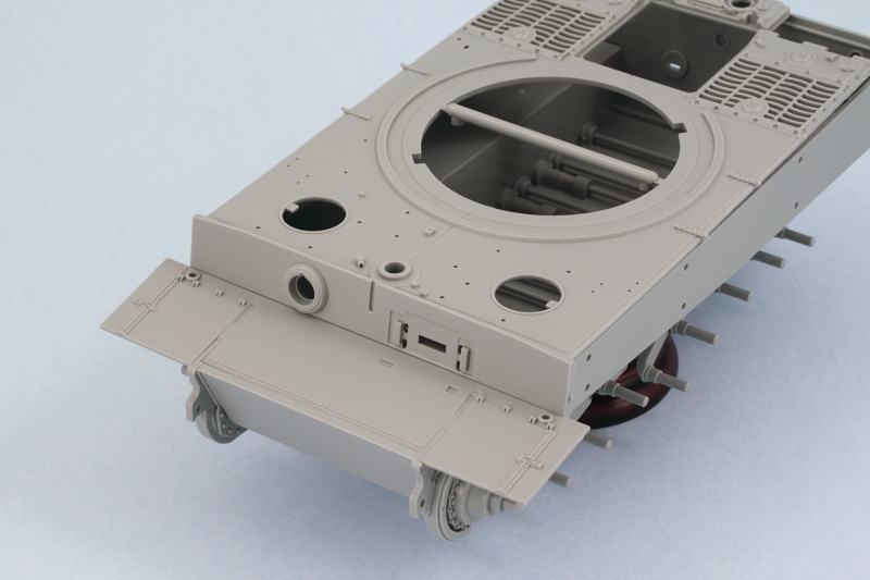
This round of effort focused on getting the remaining zim work done on the hull. First up was the left side. The kit includes pre-formed brass fenders with PE braces that need to be added to them to construct each fender portion. Dragon designed them to sit on the little mount tabs and the Atak zim set sits flush around them, so it's necessary to cut the Atak panels to allow the fenders to sit correctly. I decided to leave one of the fenders off on this side to show the detail and the zim extending down the full hull side for a little variety.
Because the hull side integrates with the front plate, I went ahead and installed it along with the glacis plate so I could get everything lined up. The three fenders were installed and some Squadron White putty used to fill back in the gaps on the zim panels where needed.
The front hull plates received their zim panels as well and the ball MG mount installed along with the driver's visor. Just a little bit of putty was needed to match things up with the zim and fill a couple of gaps.
Then the right hull side received its zim and fenders using the same approach as on the left side.
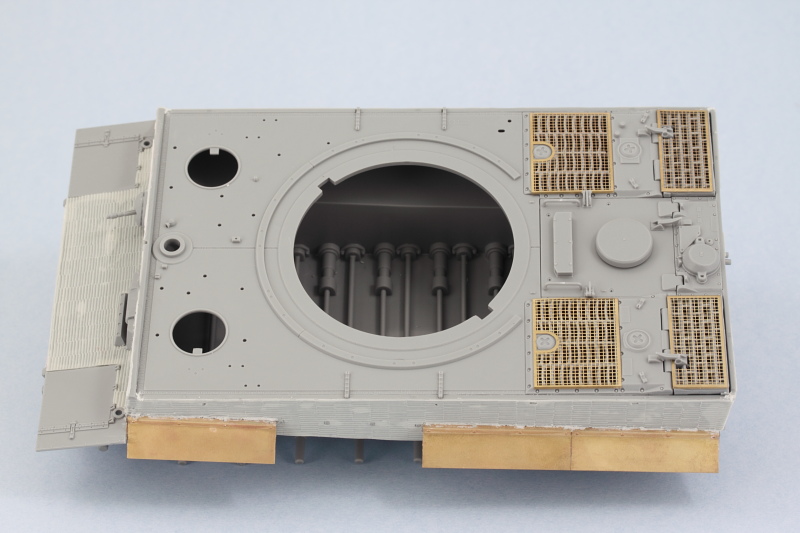
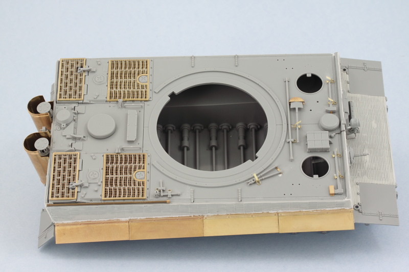
Next came the details for the engine compartment as called out in Step 7. The kit provided PE frames for the fans are a very tight fit into the space available and they also make it impossible to fit the radiator hoses (parts G13), which isn't a big deal for me since all of this disappears under the hatches and screens regardless.
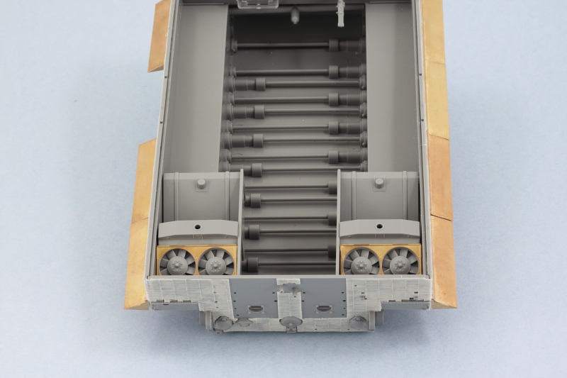
I installed the roof plate for the hull next, working at the front using liquid glue and moving slowly toward the rear to get the hull to close up properly along the edges. The engine compartment hatches were assembled and installed. It's worth noting that the part numbers in Step 11 for the fan hatches are reversed in terms of which side they belong to but nothing that isn't easily figured out with a test fit. The kit supplied larger intake PE screens were bent so some careful straightening with pliers was required before they were installed.
Rounding things out for the day, I added most of the rear hull details outlined in Steps 5 and 6. The tools and other remaining gear will be installed later on after painting.
Still more work to do on the hull before heading over to the turret.
Because the hull side integrates with the front plate, I went ahead and installed it along with the glacis plate so I could get everything lined up. The three fenders were installed and some Squadron White putty used to fill back in the gaps on the zim panels where needed.
The front hull plates received their zim panels as well and the ball MG mount installed along with the driver's visor. Just a little bit of putty was needed to match things up with the zim and fill a couple of gaps.
Then the right hull side received its zim and fenders using the same approach as on the left side.
Next came the details for the engine compartment as called out in Step 7. The kit provided PE frames for the fans are a very tight fit into the space available and they also make it impossible to fit the radiator hoses (parts G13), which isn't a big deal for me since all of this disappears under the hatches and screens regardless.
I installed the roof plate for the hull next, working at the front using liquid glue and moving slowly toward the rear to get the hull to close up properly along the edges. The engine compartment hatches were assembled and installed. It's worth noting that the part numbers in Step 11 for the fan hatches are reversed in terms of which side they belong to but nothing that isn't easily figured out with a test fit. The kit supplied larger intake PE screens were bent so some careful straightening with pliers was required before they were installed.
Rounding things out for the day, I added most of the rear hull details outlined in Steps 5 and 6. The tools and other remaining gear will be installed later on after painting.
Still more work to do on the hull before heading over to the turret.
-
Bill Plunk
- Posts: 1245
- Joined: Wed Sep 28, 2022 10:18 pm
WIP 10-20-2013
More progress in the hull details in this session. First up was the front Bosch headlight and platform. The kit part doesn't accommodate the addition of zim, so the little tab on the back needed to be notched at the top for it to sit properly. The kit-supplied pre-bent steel wire for its conduit falls into the same trap, so I replaced it with 0.5mm solder bent to shape and installed with CA gel.
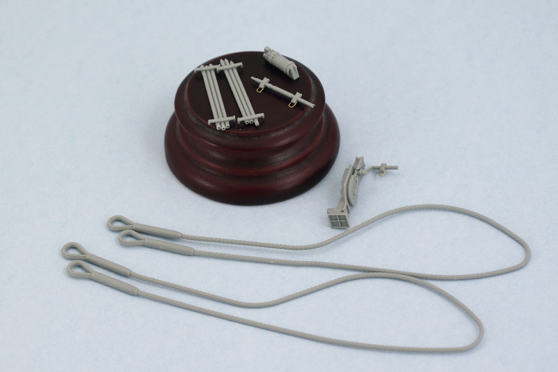
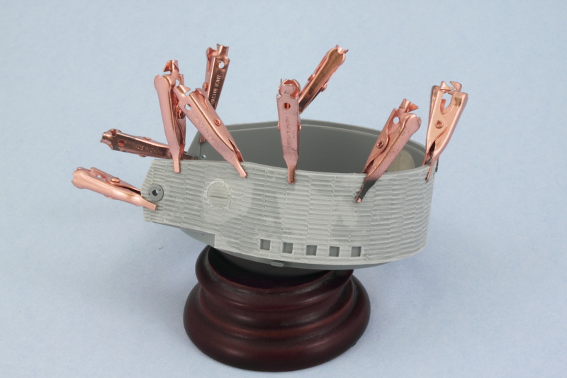
Then it was time to work on the tools. I used the kit-supplied 'clean' tools for the most part, the only one that wasn't usable was the pry bar, TA2. That's because this is a generic tool set sprue and the pry bar there is a much shorter bar than the one used on the Tiger. Griffon PE clamps were used in place of the kit clamps because I find them easier to work with. For those tools with molded-on tool clamps, I removed their thick handles and replaced them with Griffon handles. The kit-supplied brass tube antenna holder was attached with CA gel to round things out.
The tools that attach to the rear hull were also dealt with, receiving Griffon PE handle replacements. The jack is a multi-part assembly and beautifully detailed but the handle has to be placed just so to line-up properly with the mount hole in the rear. I also cleaned up the large tow cables and prepped the cleaning rods. The rods had their solid ends drilled out with a #76 finger drill to create the 'female' ends where appropriate.
Next up will begin work on the turret.
-
Bill Plunk
- Posts: 1245
- Joined: Wed Sep 28, 2022 10:18 pm
WIP 10-27-2013
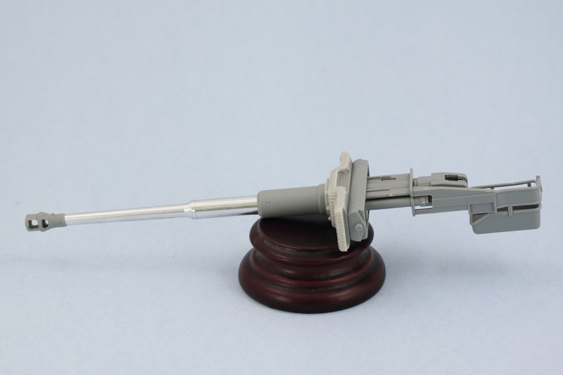
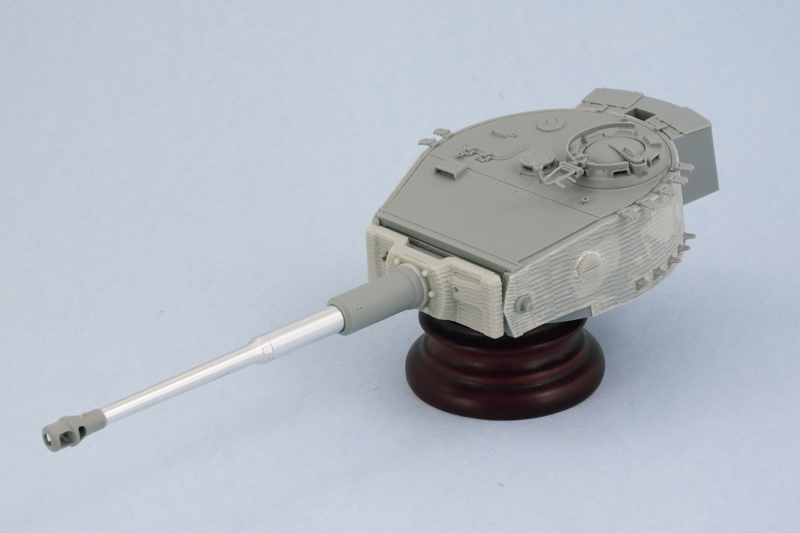
Work moved on to the turret in the latest round with efforts focused on Steps 13 and 14 to build up the main gun and mantlet. The kit includes a metal spring to allow for 'recoil' but it's not essential and I left it out deliberately. I opted for the kit-included turned aluminum barrel. The small locking piece that secures the base of the barrel into the breech and recoil housing, part A9, is shown in the instructions installing upside down. The 'open' end installs down and not up, otherwise you can't get the recoil housing halves together.
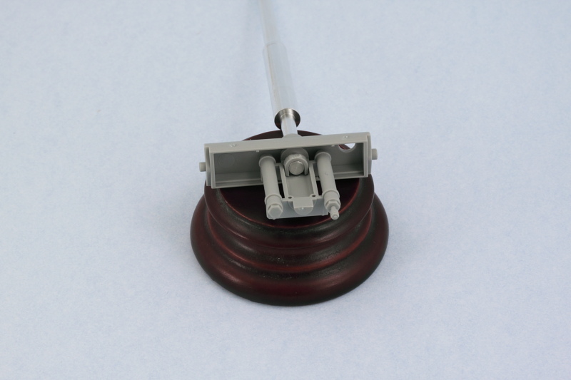
The Atak set includes two different resin replacement mantlets that have the zim pattern, The 'monocular' sight version was introduced in April '44 so I went with that one. I replaced the kit coaxial MG34 barrel with a turned brass item from JB Models. I used a small amount of ApoxieSculpt putty to provide something for the brass barrel to hold onto and also blank off the open port since the JB barrel's base diameter was smaller than that of the kit part.
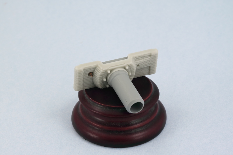
The rest of the gun was assembled per the instructions. The kit provides a choice of muzzle brakes but has the part numbers backward on the instruction diagrams. Parts A11-A17-A18 construct the larger type brake used before April '44 while parts E7-E10-E11 construct the smaller type seen after that date. I used the smaller type to match with the mantlet type selected previously. The brake has a 'D' shaped opening that has to be opened up to a full round opening to mate up with the aluminum barrel, so that was carefully drilled out with a small drill pit and pin vise.
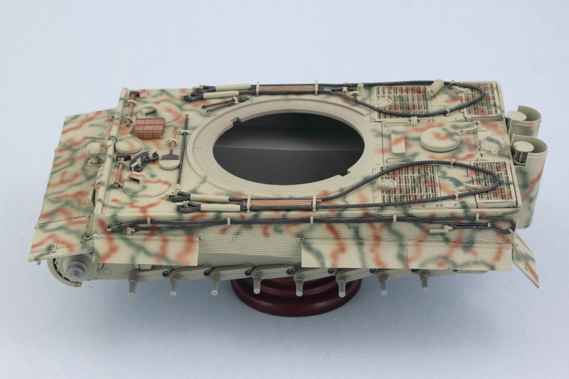
Step 15 adds interior details that I skipped since I'm not showing any of the turret hatches open. Step 16 addresses the turret roof, I chose the roof style used after June '44 and added the hatches and other details. The clear periscopes were left out for now since they can be installed into their spots from the turret underside later after painting.
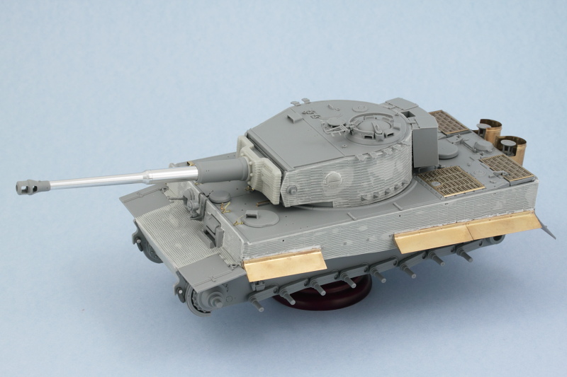
Step 17 assembles the turret but before I could do that, I needed to add the zim. The Atak set includes the choice of small or large ridge patterns panels and I opted for the larger patterns often seen on Tiger turrets vs. the smaller pattern used on the hull. Panels were added using a combination of CA gel and liquid glue since the curves of the turret put a little more stress on the panels in terms of the surfaces they needed to conform to. Strategic use of some smooth-jaw clips helped get everything to stay put until the glue set. The Atak set provides a replacement resin escape hatch as well as zimmed parts for the view ports on the turret sides. The view port parts aren't the same size as what is molded on the turret, so the turret ports were carefully sanded down until the resin parts sat flush with the zim panel. Then just a little bit of white putty to join everything up to round it out.
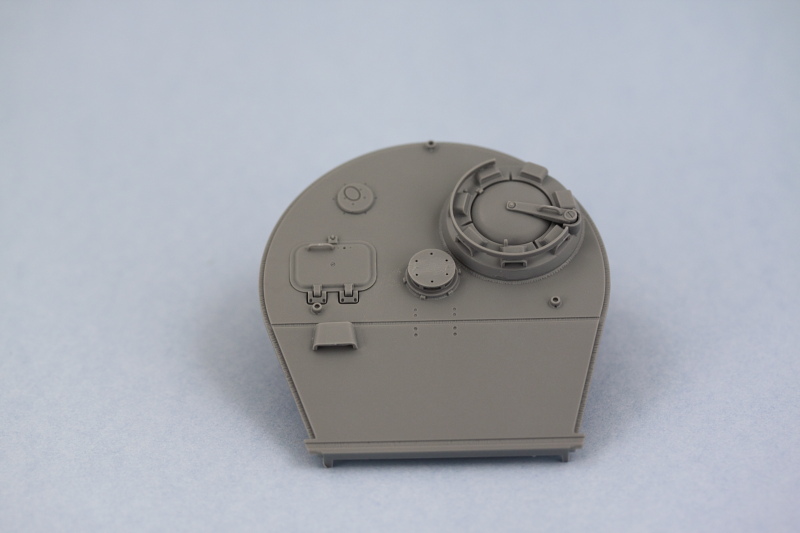
Turret roof was then installed in place and the rest of the details added in the form of the spare track holders, the rear turret bin, and the MG AA mount.
Test fit with the hull showed that I needed to adjust the placement of the shovel clamp installed earlier to allow it to clear the bottom of the mantlet. Otherwise everything else played nice.
Next up will be starting the paint work.
The Atak set includes two different resin replacement mantlets that have the zim pattern, The 'monocular' sight version was introduced in April '44 so I went with that one. I replaced the kit coaxial MG34 barrel with a turned brass item from JB Models. I used a small amount of ApoxieSculpt putty to provide something for the brass barrel to hold onto and also blank off the open port since the JB barrel's base diameter was smaller than that of the kit part.
The rest of the gun was assembled per the instructions. The kit provides a choice of muzzle brakes but has the part numbers backward on the instruction diagrams. Parts A11-A17-A18 construct the larger type brake used before April '44 while parts E7-E10-E11 construct the smaller type seen after that date. I used the smaller type to match with the mantlet type selected previously. The brake has a 'D' shaped opening that has to be opened up to a full round opening to mate up with the aluminum barrel, so that was carefully drilled out with a small drill pit and pin vise.
Step 15 adds interior details that I skipped since I'm not showing any of the turret hatches open. Step 16 addresses the turret roof, I chose the roof style used after June '44 and added the hatches and other details. The clear periscopes were left out for now since they can be installed into their spots from the turret underside later after painting.
Step 17 assembles the turret but before I could do that, I needed to add the zim. The Atak set includes the choice of small or large ridge patterns panels and I opted for the larger patterns often seen on Tiger turrets vs. the smaller pattern used on the hull. Panels were added using a combination of CA gel and liquid glue since the curves of the turret put a little more stress on the panels in terms of the surfaces they needed to conform to. Strategic use of some smooth-jaw clips helped get everything to stay put until the glue set. The Atak set provides a replacement resin escape hatch as well as zimmed parts for the view ports on the turret sides. The view port parts aren't the same size as what is molded on the turret, so the turret ports were carefully sanded down until the resin parts sat flush with the zim panel. Then just a little bit of white putty to join everything up to round it out.
Turret roof was then installed in place and the rest of the details added in the form of the spare track holders, the rear turret bin, and the MG AA mount.
Test fit with the hull showed that I needed to adjust the placement of the shovel clamp installed earlier to allow it to clear the bottom of the mantlet. Otherwise everything else played nice.
Next up will be starting the paint work.
-
Bill Plunk
- Posts: 1245
- Joined: Wed Sep 28, 2022 10:18 pm
WIP 11-03-2013
I had a couple of small details to attend to on the build before paint work could begin. Those details involved the spare tracks. The 7 links that mount to the turret were missing their individual pin details so I used some 0.8mm diameter styrene rod to recreate the pins on each link. I also drilled out the exposed end of each link to show the empty pin hole at the top that's exposed once they are mounted in their holders.
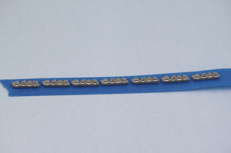
For the front spare track run, I used the remaining links I had from the MK set for the 12 links required there. There weren't enough links left over in the MK set to do this and the turret links and since the workables are better suited here, that's where they got used. The instructions for this little addition are in Step 12 but they parts callout for the support bar is wrong, it should be K3 and not C15.
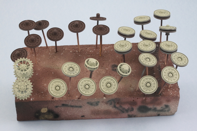
With that done, I prepped the vehicle for painting by masking off all the suspension arm mount points with blue-tack to prevent paint build-up from causing an issue with the wheel fit later on. I also mounted all the wheels, sprockets, and idlers on toothpicks with blue tack to make it easier to deal with them, fitted a temporary handle to the turret in the form of a cardboard toilet-paper cylinder cut down to size and let the paint fly.
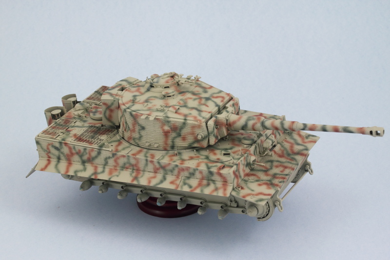
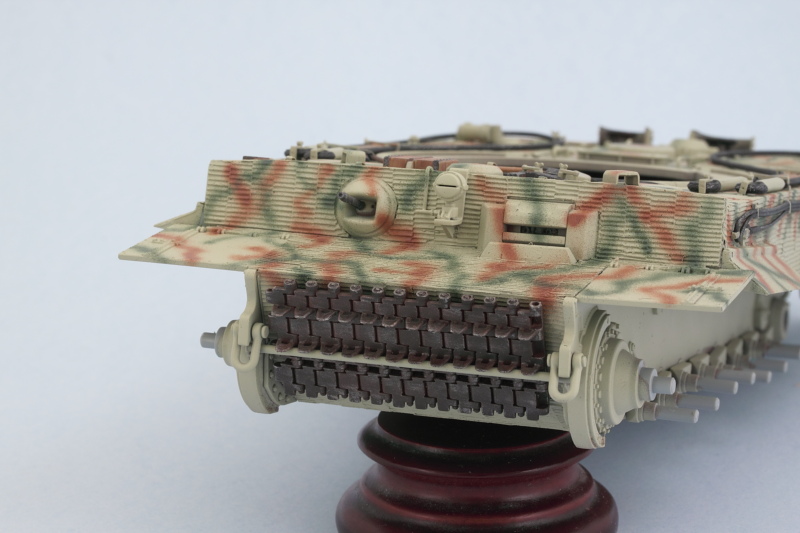
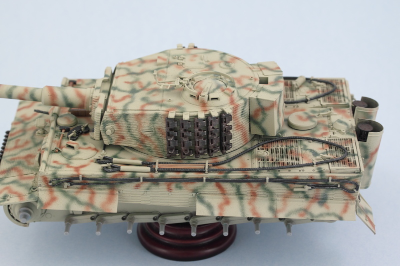
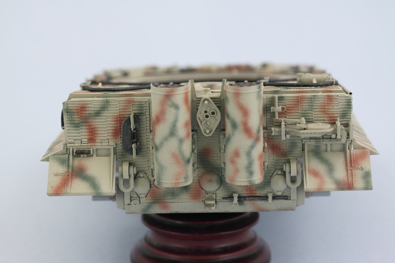
First up was an overall primer treatment using MM enamel Italian Dark Brown. The zimmed surfaces exponentially increase the surface area so more paint than usual was required to get complete coverage.
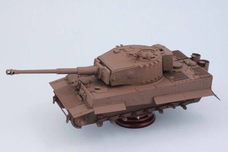
Next came the base coat using a custom mix of 50/50 MM enamel Panzer Dunkelgelb and enamel Light Gray.

Same treatment was applied to the road wheels, sprockets, and idlers. Since everything's all steel wheels, that sped up the process here a little bit but I still have to paint and detail the contact surfaces for them before they are fully detailed.
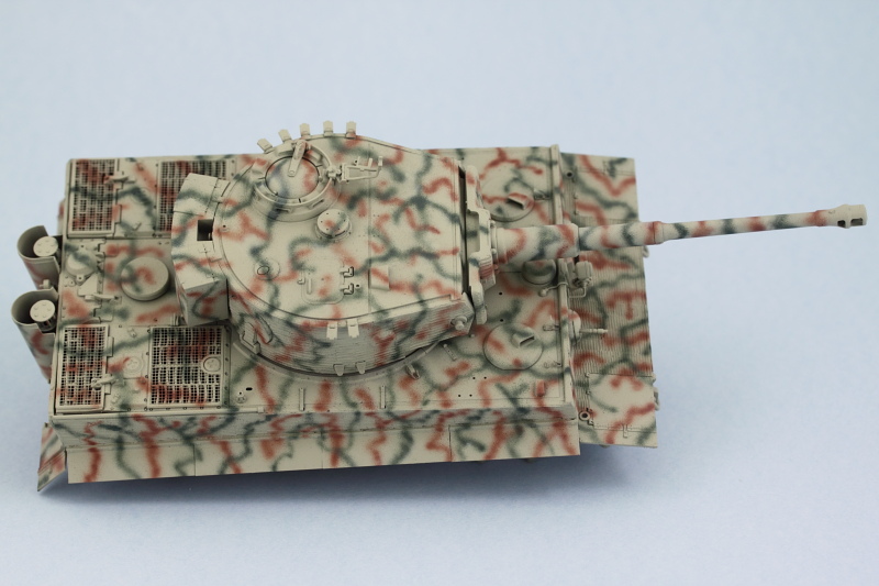
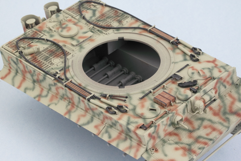
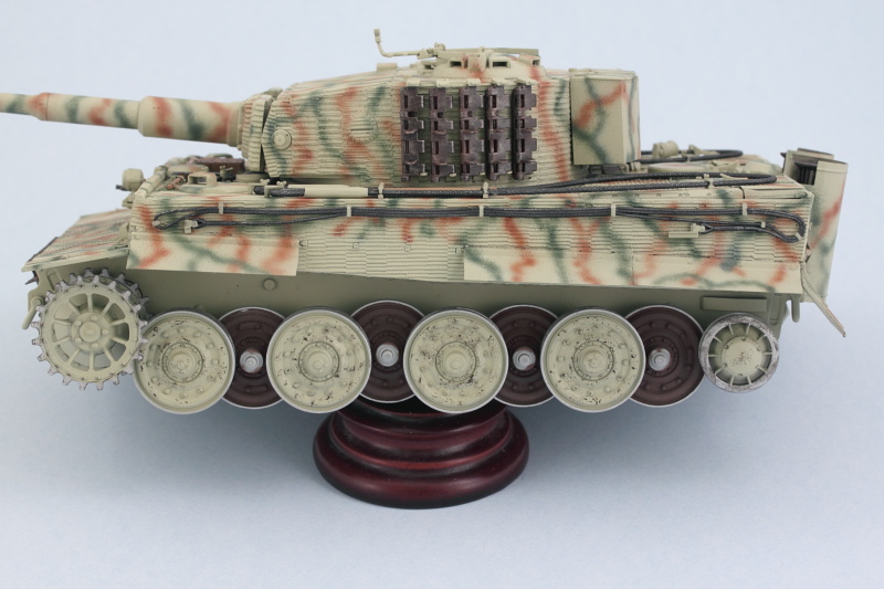
Then the real fun began with the application of the camo pattern. First I applied the rot-braun elements using a custom mix of 50/50 MM enamel Military Brown and Leather and then the olivgrun elements using MM enamel Khaki. Final step involved spraying a mist coat/filter of the original base coat highly thinned from a distance of about 12 inches to help tie everything together.
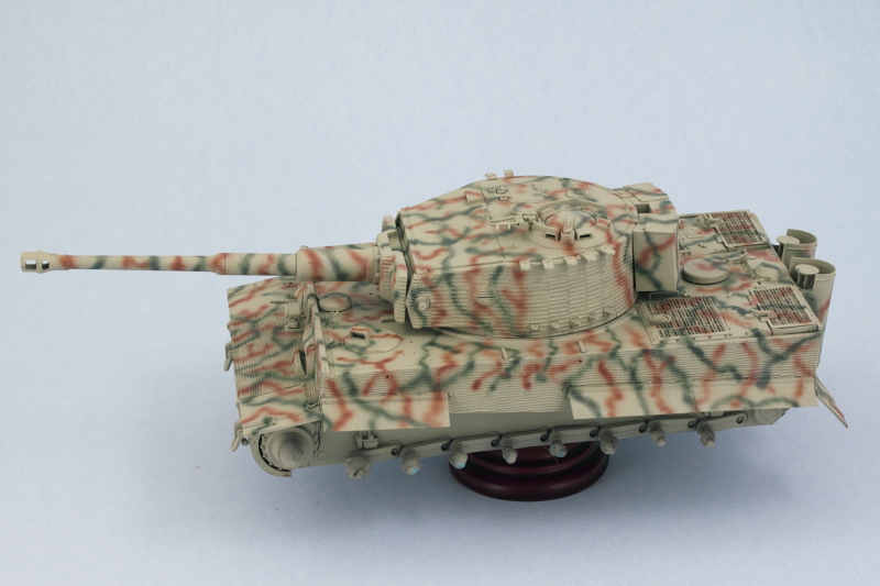
Top down view shows what it would've looked like from the air.
This will get a chance to sit and cure up thoroughly before moving on to the next phases. Still a lot of work to do in the details department as well with the tools and suspension.
For the front spare track run, I used the remaining links I had from the MK set for the 12 links required there. There weren't enough links left over in the MK set to do this and the turret links and since the workables are better suited here, that's where they got used. The instructions for this little addition are in Step 12 but they parts callout for the support bar is wrong, it should be K3 and not C15.
With that done, I prepped the vehicle for painting by masking off all the suspension arm mount points with blue-tack to prevent paint build-up from causing an issue with the wheel fit later on. I also mounted all the wheels, sprockets, and idlers on toothpicks with blue tack to make it easier to deal with them, fitted a temporary handle to the turret in the form of a cardboard toilet-paper cylinder cut down to size and let the paint fly.
First up was an overall primer treatment using MM enamel Italian Dark Brown. The zimmed surfaces exponentially increase the surface area so more paint than usual was required to get complete coverage.
Next came the base coat using a custom mix of 50/50 MM enamel Panzer Dunkelgelb and enamel Light Gray.
Same treatment was applied to the road wheels, sprockets, and idlers. Since everything's all steel wheels, that sped up the process here a little bit but I still have to paint and detail the contact surfaces for them before they are fully detailed.
Then the real fun began with the application of the camo pattern. First I applied the rot-braun elements using a custom mix of 50/50 MM enamel Military Brown and Leather and then the olivgrun elements using MM enamel Khaki. Final step involved spraying a mist coat/filter of the original base coat highly thinned from a distance of about 12 inches to help tie everything together.
Top down view shows what it would've looked like from the air.
This will get a chance to sit and cure up thoroughly before moving on to the next phases. Still a lot of work to do in the details department as well with the tools and suspension.
-
Bill Plunk
- Posts: 1245
- Joined: Wed Sep 28, 2022 10:18 pm
WIP 11-10-2013
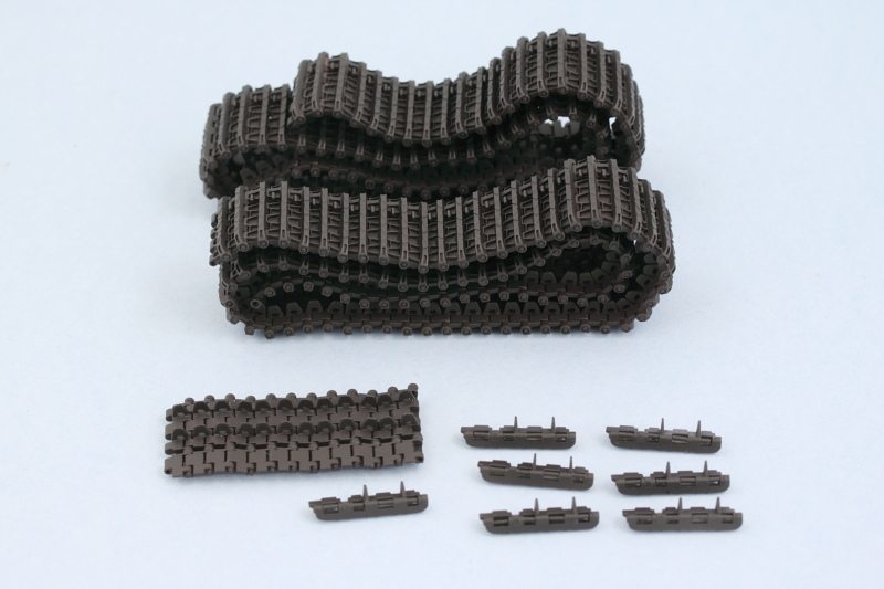
Not a lot of photos in this update round but definitely a lot of progress. I got the tracks ready for more work later on by airbrushing a base coat of MM enamel Burnt Umber. This is just the first step in their finishing and weathering process of course.
Attention then shifted to the details for the hull. All of the tools and tow cables that I'd cleaned up earlier were now hand detailed and installed. The larger tow cables proved more of a challenge than I expected as they kept wanting to lift up out of their mounts on the rear deck. Some finger pressure and liquid glue provided the necessary persuasion to get them to ultimately settle down.
Next up will be continuing work on the remaining hull and turret details before moving on to the suspension and tracks.
-
Bill Plunk
- Posts: 1245
- Joined: Wed Sep 28, 2022 10:18 pm
WIP 11-17-2013
More progress to report in the details department. Following on from last week's efforts, I turned my attention to the remaining hull details first. The spare track run for the front hull and the turret individual links were given a light dry-brush of MM enamel Steel followed by a wash of MM enamel Rust. Then some burnt orange and raw umber artist pastels were worked into their finish to add some additional depth/layering. I also detailed the hull MG and coaxial MG in the turret using a base coat of MM non-buffing Metalizer Gunmetal followed by a light dry-brush of Steel. Rounding things out, I also detailed the exhausts using a base of metalizer Gunmetal followed by a heavy wash of enamel Rust and then some artist pastels using the same colors as the tracks as well as black for some soot staining.

The rear hull also received some attention. The tools were installed in their respective positions and the rear Notek convoy light added. I used Tamiya Clear Smoke for the light's body
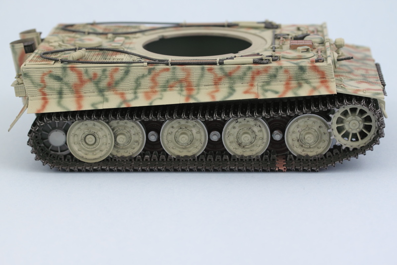
Efforts shifted back to the suspension and I detailed the road wheels using MM non-buffing Metalizer Steel for the wheels contact surfaces as well as the idlers and sprocket teeth. Some enamel Burnt Umber was stippled on the wheels to simulate scuffing/wear in anticipation of more weathering to come. The innermost wheels were left in primer since they get hidden away and the middle wheel pairs were installed in place while the outer wheels were left off for now to make it easier to weather them separately prior to their installation. Sprockets and idlers are dry-fit only at this point as well.
Tracks also received some attention as well. Dry brush pass with MM enamel Steel followed by a wash of MM enamel Raw Umber to tone things down and get them ready for the pigment weathering later on.
Next up will be dealing with the markings!
The rear hull also received some attention. The tools were installed in their respective positions and the rear Notek convoy light added. I used Tamiya Clear Smoke for the light's body
Efforts shifted back to the suspension and I detailed the road wheels using MM non-buffing Metalizer Steel for the wheels contact surfaces as well as the idlers and sprocket teeth. Some enamel Burnt Umber was stippled on the wheels to simulate scuffing/wear in anticipation of more weathering to come. The innermost wheels were left in primer since they get hidden away and the middle wheel pairs were installed in place while the outer wheels were left off for now to make it easier to weather them separately prior to their installation. Sprockets and idlers are dry-fit only at this point as well.
Tracks also received some attention as well. Dry brush pass with MM enamel Steel followed by a wash of MM enamel Raw Umber to tone things down and get them ready for the pigment weathering later on.
Next up will be dealing with the markings!
-
Bill Plunk
- Posts: 1245
- Joined: Wed Sep 28, 2022 10:18 pm
WIP 11-23-2013
A minor mishap occurred in the Tiger's progress today. It seems that one of the idlers managed to go missing and as I was searching for it, my 75 lb. Boxer named Brenda found it before I did. Here's all that was left after her adventure!

Thankfully the kit includes the larger idlers as additional parts but doesn't provide additional mount arms. Old kits in the closet to the rescue! I salvaged a mount arm off a previously built Tamiya Tiger and made some slight modifications to it so it would fit the Dragon parts. Installed the rear-most outer wheel to help serve as a guide for the idler's placement and did a test-fit with the MK track run. As expected 1 more link was needed due to the larger idler. Once that was added, the idler was glued permanently into position and left to set up and will get painted later to match the rest of the suspension. So now my Tiger has a little extra character courtesy of Brenda's 'assistance'!
Now back to work and what was actually scheduled for today...the markings.