Cyber Hobby Pzkpfw VI Ausf. E Sdkfz 181 Gruppe Fehrmann Tiger I (2016)
-
Bill Plunk
- Posts: 1245
- Joined: Wed Sep 28, 2022 10:18 pm
Cyber Hobby Pzkpfw VI Ausf. E Sdkfz 181 Gruppe Fehrmann Tiger I (2016)
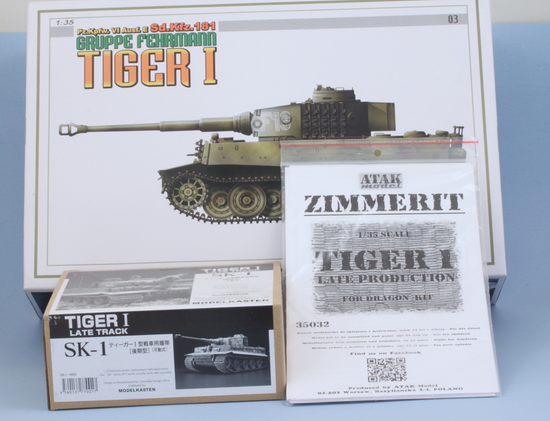
Build log for Cyber Hobby (Dragon) kit #6335 with Atak Zimmerit and Model Kasten workable tracks.
-
Bill Plunk
- Posts: 1245
- Joined: Wed Sep 28, 2022 10:18 pm
References
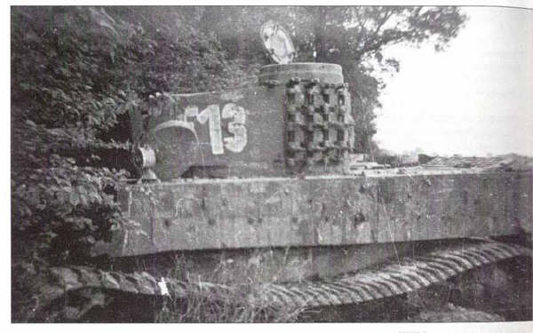
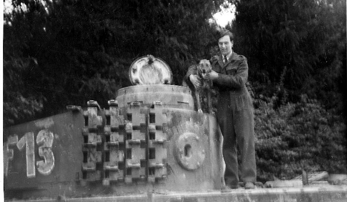
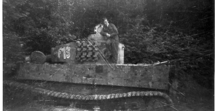
F13 is a kind of one-off oddball tank that was thrown together with other vehicles into a makeshift unit, Gruppe Fehrmann, in April 1945. Not much is available in terms of photo references as a result but these three photos of it knocked out in the Ruhr area will help pull it all together. 
-
Bill Plunk
- Posts: 1245
- Joined: Wed Sep 28, 2022 10:18 pm
WIP 01-02-2016
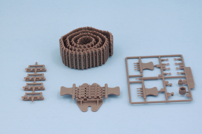
Every build has to start somewhere and usually with a German tank that usually involves the road wheels. Since I'm replacing the one-piece DS tracks with the workable MK tracks, I built up a short section of 10 links on the MK tracks to use as a fit gauge to make sure everything would play nice in this department. The MK set includes a jig that holds 5 links at a time and the guide horns are separate parts, so it's important to get things to line up properly to avoid problems down the road.
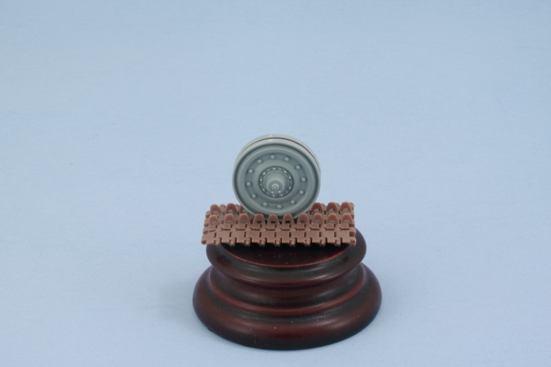
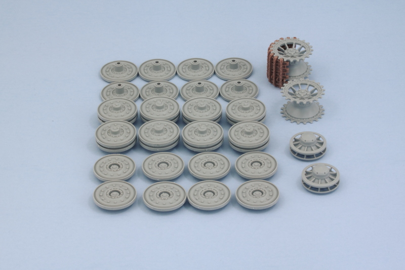
Then the 32 road wheel parts were removed from the sprues, cleaned up, and their mold seams removed with a sanding stick. The middle wheel halves were assembled together while the inner and outer wheels were left separate for obvious reasons for now. Two different styles of wheels are provided in the kit, I went with the G2-G6 combo because I had to pick one so it was a coin flip decision. The sprockets and idlers were also cleaned up and assembled to round out the day's efforts.
Next up will be adding the suspension bars into the lower hull.
Then the 32 road wheel parts were removed from the sprues, cleaned up, and their mold seams removed with a sanding stick. The middle wheel halves were assembled together while the inner and outer wheels were left separate for obvious reasons for now. Two different styles of wheels are provided in the kit, I went with the G2-G6 combo because I had to pick one so it was a coin flip decision.
Next up will be adding the suspension bars into the lower hull.
-
Bill Plunk
- Posts: 1245
- Joined: Wed Sep 28, 2022 10:18 pm
WIP 01-07-2016
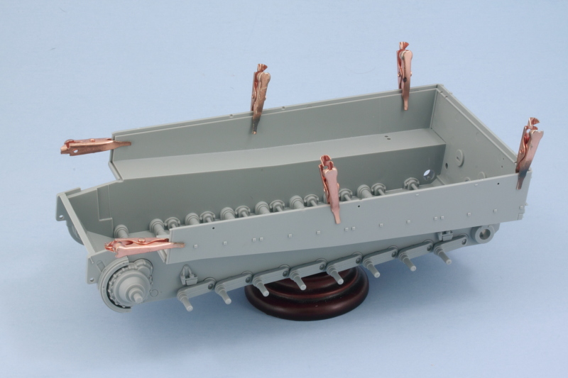
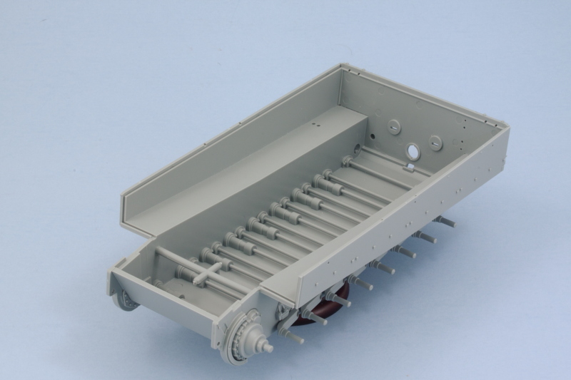
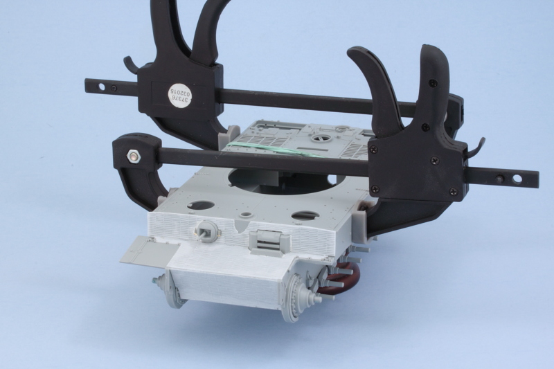
Finished off the remaining work on the first 3 steps in the instructions that deal with the suspension. First order of business was installing all of the torsion bars and their locking parts. That involved another 32 pieces but produces a nicely working suspension in the process so it's worth it. I used a pair of smooth copper clamps to ensure the final drive housings sat flush. Dragon designed the hull to flex inward at the top to help with the fit with the top hull and that will need a sprue spreader to correct but I'll deal with that later when I'm ready to construct that part.
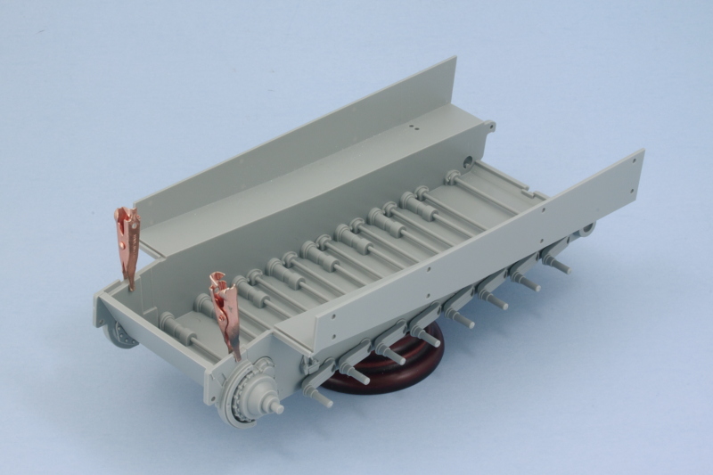
I applied some careful amounts of liquid glue to the ends of the torsion bars that go into the locking parts inside the hull and dry fit the road wheels to make sure everything would set level.
That sets things up beautifully for the NFL playoffs as those kinds of games make for a great opportunity to build tracks in my experience while the game is on in the background.
-
Bill Plunk
- Posts: 1245
- Joined: Wed Sep 28, 2022 10:18 pm
WIP 01-11-2016
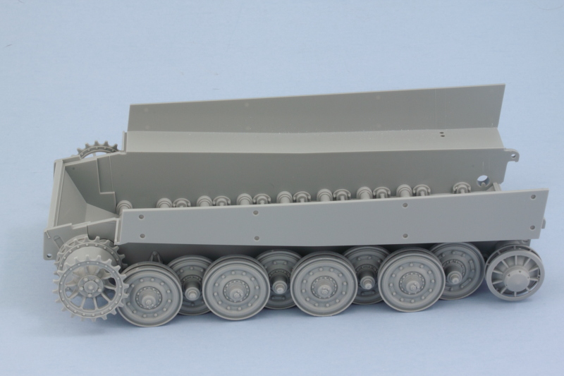
Wild Card weekend was as good a time as any to begin the time-consuming job of tackling the tracks. Between the 4 games I managed to get the first track built. The MK set calls for 95 links per side but I found that only 94 did the trick nicely for the first one. Test fits with the sprocket and idler held in place with some blue-tack shows the sag produced using the large idler wheel option on the suspension.
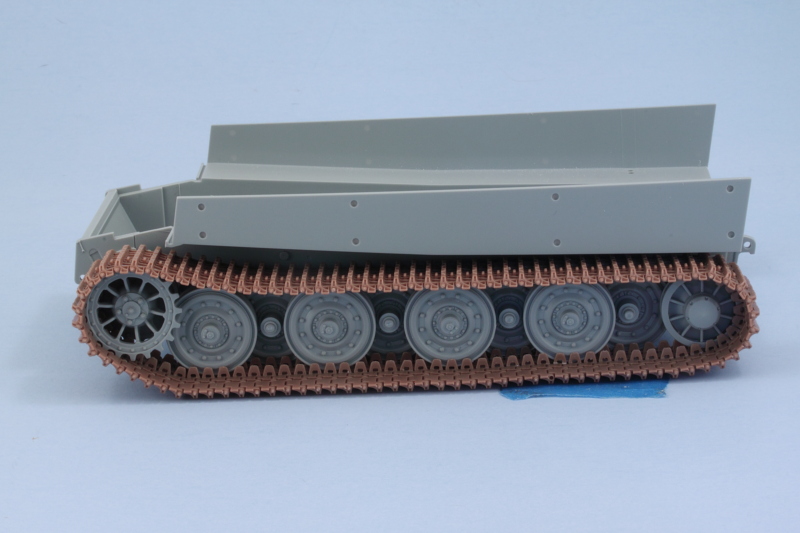
Building the tracks is a pretty straightforward exercise. The MK set includes a jig that holds 5 links at a time and the pins are provided on handles that are designed to work with the jig to create the sections. Individual pins are provided to connect them together into the long run but occasionally you need to use some of the pins on the 4-pin groups as there aren't quite enough single pins to do the job. The 2 guide horns are separate parts that are installed per link to complete the job. The first track run consisted of 94 links or 470 total parts including the pins and took roughly 6 hours to get together.
One down, one to go! Since the fenders weren't fitted to the Fehrmann, the tracks are going to be an important visual detail on this baby given their exposed nature.
Building the tracks is a pretty straightforward exercise. The MK set includes a jig that holds 5 links at a time and the pins are provided on handles that are designed to work with the jig to create the sections. Individual pins are provided to connect them together into the long run but occasionally you need to use some of the pins on the 4-pin groups as there aren't quite enough single pins to do the job. The 2 guide horns are separate parts that are installed per link to complete the job. The first track run consisted of 94 links or 470 total parts including the pins and took roughly 6 hours to get together.
One down, one to go!
-
Bill Plunk
- Posts: 1245
- Joined: Wed Sep 28, 2022 10:18 pm
WIP 01-17-2016
Another round of playoff games this weekend meant more time working on the tracks! 2nd verse, same as the first!
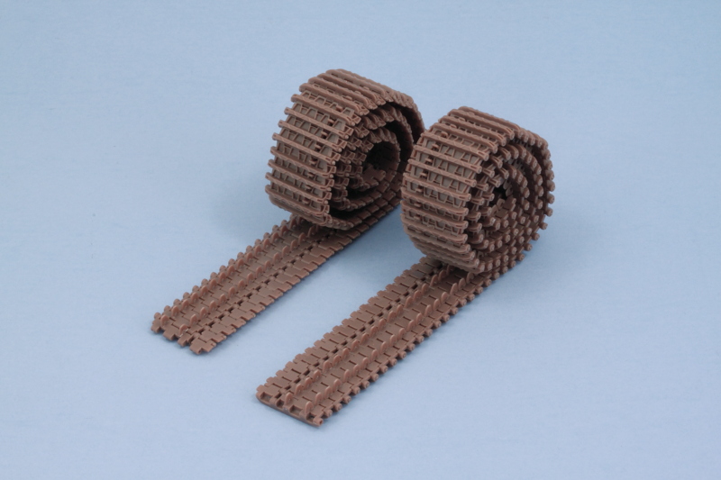
Both tracks are now done with 94 links per side and 940 parts in total. That leaves 10 extras in the set that are enough to populate the turret racks but not the front hull run. That will have to involve the kit-supplied individual links but won't be a big deal in the end.
Both tracks are now done with 94 links per side and 940 parts in total. That leaves 10 extras in the set that are enough to populate the turret racks but not the front hull run. That will have to involve the kit-supplied individual links but won't be a big deal in the end.
-
Bill Plunk
- Posts: 1245
- Joined: Wed Sep 28, 2022 10:18 pm
WIP 01-25-2016
Haven't had a ton of time to work on things but still managed to make enough progress to be update-worthy. I started work on the hull proper by adding in the rear plate as called for in Step 4 but held off adding all of its details just yet. The hull side panels are called out in Step 7 and those were added at the same time to make sure they lined up with the rear plate correctly. Some small copper smooth-jaw clamps helped as the inner sides of the hull kept wanting to bow out slightly.
Next up I needed to address the slight hull warp that exists at the glacis area. Dragon deliberately designed the hull this way with the intent of helping ensure a tight fit but it just makes life harder, not easier, so a short length of sprue was cut to length and used as a spreader. After getting the right tension, I used some liquid glue at the ends to help lock it in place.
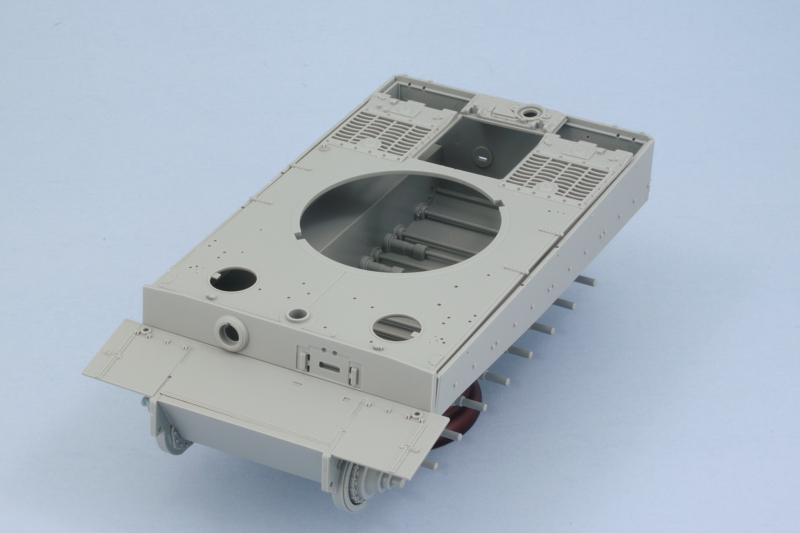
A quick test-fit with the hull roof, the front plate, and the glacis shows that things are working okay together if not quite perfectly. There's a small gap present with the hull roof and sides but that can be closed up when the hull roof is attached later using some rubber bands, finger pressure, and patience.
Once the spreader is set, I can go about getting the rest of the hull components together before starting in adding the zim panels.
Next up I needed to address the slight hull warp that exists at the glacis area. Dragon deliberately designed the hull this way with the intent of helping ensure a tight fit but it just makes life harder, not easier, so a short length of sprue was cut to length and used as a spreader. After getting the right tension, I used some liquid glue at the ends to help lock it in place.
A quick test-fit with the hull roof, the front plate, and the glacis shows that things are working okay together if not quite perfectly. There's a small gap present with the hull roof and sides but that can be closed up when the hull roof is attached later using some rubber bands, finger pressure, and patience.
Once the spreader is set, I can go about getting the rest of the hull components together before starting in adding the zim panels.
-
Bill Plunk
- Posts: 1245
- Joined: Wed Sep 28, 2022 10:18 pm
WIP 01-28-2016
One of the inevitable conditions of a 'thrown-together' kit like these Cyberhobby combinations vs. a 'purpose designed' kit is that while all of the necessary elements are there, they weren't all designed to work together as a whole kit. This introduces some little discrepancies along the way but nothing that isn't insurmountable...but you do have to watch out for them. A couple of them popped up today while I was working on getting the hull together. More on that below.
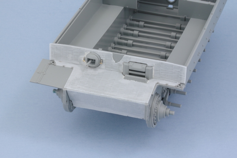
First order of business was getting the glacis and front plate ready to go. The instructions would have you install the glacis plate first and then add the hull top with the front plate already attached to it in Step 13. That not only produces an inaccurate layout, it's impossible to do as the glacis rests on top of a shelf at the base of the front plate and not the other way around. After looking at the reference pics, I decided to remove the left side front fender but left the right one in place since I can't be sure if it was or wasn't attached. I also added the Atak zim panels using a combination of Gator Grip Thin Blend glue and liquid glue run around the edges after the panels were in place to lock everything down. Squadron white putty helped fill in some small gaps and I removed a small section on the front plate with some curved scissors to simulate some chipping damage to the zim. F13 is pretty beat-up in the photos and while I won't be showing it as a knocked out vehicle, some of the wear and tear it's sporting will be included. The PE parts for the ball MG cover are mislabelled as M4 when they are actually M40 on the fret.
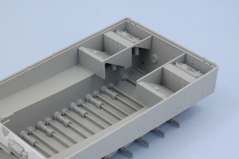
While that set, I added the engine bay details for the hull interior. The radiator tops and hoses can't be installed without interfering with the hull top, so they were left off. I will also be posing the rear deck hatches closed so I didn't bother with the PE details there either. There just needs to be something there through the grating as once the PE screens are added and it's all painted, visibility into the interior is near zero.
The hull nose plates received their zim panels as well and the glacis and front plate were installed permanently into position. I didn't apply glue to the sides of the front plate where they mate up with the hull sides just yet as they needed to be able to flex a bit to match up with the hull roof.
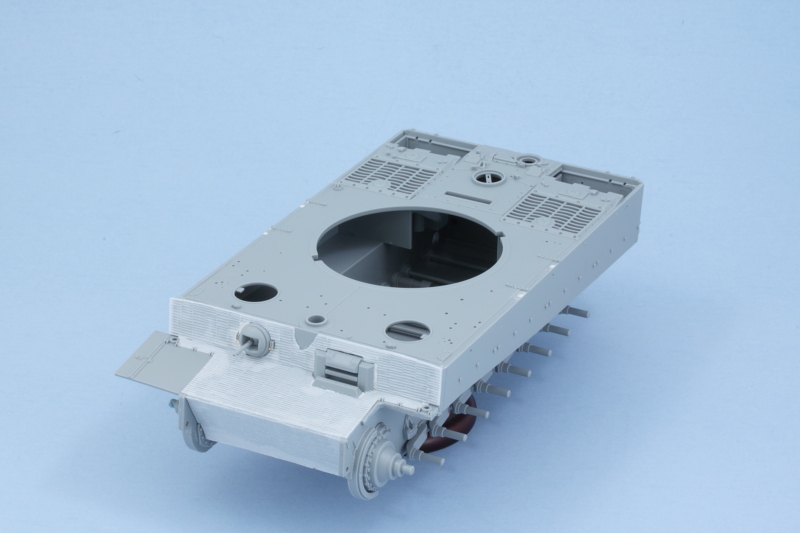
Speaking of that, the roof was added next. I started at the front and worked my way back to the rear. Liquid glue was run into the seams and a combination of finger pressure and light use of compression clamps got it together. I had to be careful at the front as too much pressure from the clamps would cause the roof to bulge upward, not a good thing!
One the roof was set, the clamps came off and I had to fix a couple of spots on either side with some Squadron White putty. The alignment of the cleaning rod holders on the roof plate doesn't match up with the notches on the hull because these come from two different kits.
That will get a chance to set solid overnight and tomorrow I'll work on the rear hull plate and possibly also the side panels if time permits.
First order of business was getting the glacis and front plate ready to go. The instructions would have you install the glacis plate first and then add the hull top with the front plate already attached to it in Step 13. That not only produces an inaccurate layout, it's impossible to do as the glacis rests on top of a shelf at the base of the front plate and not the other way around.
While that set, I added the engine bay details for the hull interior. The radiator tops and hoses can't be installed without interfering with the hull top, so they were left off. I will also be posing the rear deck hatches closed so I didn't bother with the PE details there either. There just needs to be something there through the grating as once the PE screens are added and it's all painted, visibility into the interior is near zero.
The hull nose plates received their zim panels as well and the glacis and front plate were installed permanently into position. I didn't apply glue to the sides of the front plate where they mate up with the hull sides just yet as they needed to be able to flex a bit to match up with the hull roof.
Speaking of that, the roof was added next. I started at the front and worked my way back to the rear. Liquid glue was run into the seams and a combination of finger pressure and light use of compression clamps got it together. I had to be careful at the front as too much pressure from the clamps would cause the roof to bulge upward, not a good thing!
One the roof was set, the clamps came off and I had to fix a couple of spots on either side with some Squadron White putty. The alignment of the cleaning rod holders on the roof plate doesn't match up with the notches on the hull because these come from two different kits.
That will get a chance to set solid overnight and tomorrow I'll work on the rear hull plate and possibly also the side panels if time permits.
-
Bill Plunk
- Posts: 1245
- Joined: Wed Sep 28, 2022 10:18 pm
WIP 01-29-2016
More fun with the zim panels today, this time around I focused on the side panels first. The reference pics for F13 show it pretty beat up but also clearly heavily battle damaged as a result of the action it was involved in. As a result, I decided to have some damage to the left side panel but not of the catastrophic variety. The turret is also going to get a lot of its zim removed/chipped up too, so some restraint is called for to avoid it overpowering the final look. Working from the photo, I used some small curved scissors and the fender mount points as landmarks to create the damaged areas. The zim panels are thin and a little fragile, so the small scissors did the job beautifully. I added some more small knicks and variations with a sharp #11 knife point.

One thing that Dragon/CH overlooked with the front plate is that it's missing the final fender mount hub...it's present on the unused other part that is correct for the standard Late Tiger but not on the part F20 that is used on this Tiger...so I had to scrounge up some replacements. I found the perfect solution on the TE sprue...there are 4 padlock bodies there that aren't going to be used since they are designed for the turret stowage bin and F13 didn't have a bin. Some careful sanding/trimming had them down to the right size and glued in place. The right side zim panel was added fully intact to counter the damaged left side.

The last of the hull zim was added to the rear plate to get it ready for the details that install there.

Following the diagrams in Steps 5 and 6, I added the rear plate details. There's a weird error...the cold weather starter (Y10 or Y7) is first shown installed, correctly, on the support posts between the exhausts and then in the next diagram it's shown with arrows installing into the already covered crank starter port! I suppose you could do that if you wanted to for a dio or similar...but definitely not appropriate for the F13 build. I filled in the holes in the zim panel that were intended to take a C towing hook since that's not correct for this Tiger. I also left off the tool box and shelf that the instructions call for in Step 6 as it's clear in the reference photo that this also wasn't present on F13.
While the instructions indicate that the heat shields, parts C8 and C9, are an optional feature, I left them off as those are also clearly missing from F13 in the photo. The jack and small tool that goes under the exhausts will get added in later after the hull has been painted.

All in all a good day's progress! Next up will be getting the rest of the engine deck stuff squared away.
One thing that Dragon/CH overlooked with the front plate is that it's missing the final fender mount hub...it's present on the unused other part that is correct for the standard Late Tiger but not on the part F20 that is used on this Tiger...so I had to scrounge up some replacements. I found the perfect solution on the TE sprue...there are 4 padlock bodies there that aren't going to be used since they are designed for the turret stowage bin and F13 didn't have a bin. Some careful sanding/trimming had them down to the right size and glued in place. The right side zim panel was added fully intact to counter the damaged left side.
The last of the hull zim was added to the rear plate to get it ready for the details that install there.
Following the diagrams in Steps 5 and 6, I added the rear plate details. There's a weird error...the cold weather starter (Y10 or Y7) is first shown installed, correctly, on the support posts between the exhausts and then in the next diagram it's shown with arrows installing into the already covered crank starter port! I suppose you could do that if you wanted to for a dio or similar...but definitely not appropriate for the F13 build.
While the instructions indicate that the heat shields, parts C8 and C9, are an optional feature, I left them off as those are also clearly missing from F13 in the photo. The jack and small tool that goes under the exhausts will get added in later after the hull has been painted.
All in all a good day's progress! Next up will be getting the rest of the engine deck stuff squared away.
-
Bill Plunk
- Posts: 1245
- Joined: Wed Sep 28, 2022 10:18 pm
WIP 01-30-2016
Made some progress today with the engine deck details as called out in Steps 8 and 10. It's important to note that while the rear access hatches are designed with pins to make them positionable, Dragon neglected to take into account that they also have notch tabs that align with the main deck plate that make it impossible to fit them from underneath as they would have you do it. The solution is simple, just remove the pins and install them at the position desired. In my case, fully closed!
The middle access panel has 4 mount holes that are meant to take the brackets for a set of Feifel air cleaner hoses but never tells you to fill them in. In fact, they continue in the diagram drawings showing them open right to the end of the instructions. Easily resolved with some putty, but best done before you fit the round J13 cover...ask me how I know that.
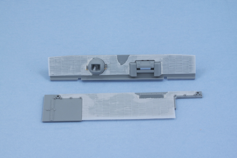
Last but not least, I added the pre-formed brass screens for the deck grilles. Be careful not to install the J19 latches on the rear hatches until after the screens are in place or the screens can't fit over them otherwise.
As a small added touch, I had a scrap of resin zim left over that I added to the front corner of the left hull side to add a little more variety in that spot.


As you can see, there's a lot of open holes all over the front half of the hull roof meant to take various tools and other bits of gear. I'll have to evaluate those next and see what will stay or go depending on their location.
The middle access panel has 4 mount holes that are meant to take the brackets for a set of Feifel air cleaner hoses but never tells you to fill them in. In fact, they continue in the diagram drawings showing them open right to the end of the instructions. Easily resolved with some putty, but best done before you fit the round J13 cover...ask me how I know that.
Last but not least, I added the pre-formed brass screens for the deck grilles. Be careful not to install the J19 latches on the rear hatches until after the screens are in place or the screens can't fit over them otherwise.
As a small added touch, I had a scrap of resin zim left over that I added to the front corner of the left hull side to add a little more variety in that spot.
As you can see, there's a lot of open holes all over the front half of the hull roof meant to take various tools and other bits of gear. I'll have to evaluate those next and see what will stay or go depending on their location.