Tamiya Russian Self-Propelled Gun SU-76M (2016)
-
Bill Plunk
- Posts: 1245
- Joined: Wed Sep 28, 2022 10:18 pm
Tamiya Russian Self-Propelled Gun SU-76M (2016)
Build log for the 1/35 Tamiya kit #35348 SU-76M Russian Self-Propelled Gun. This will be done as an OOB build.
-
Bill Plunk
- Posts: 1245
- Joined: Wed Sep 28, 2022 10:18 pm
WIP 03-18-2016
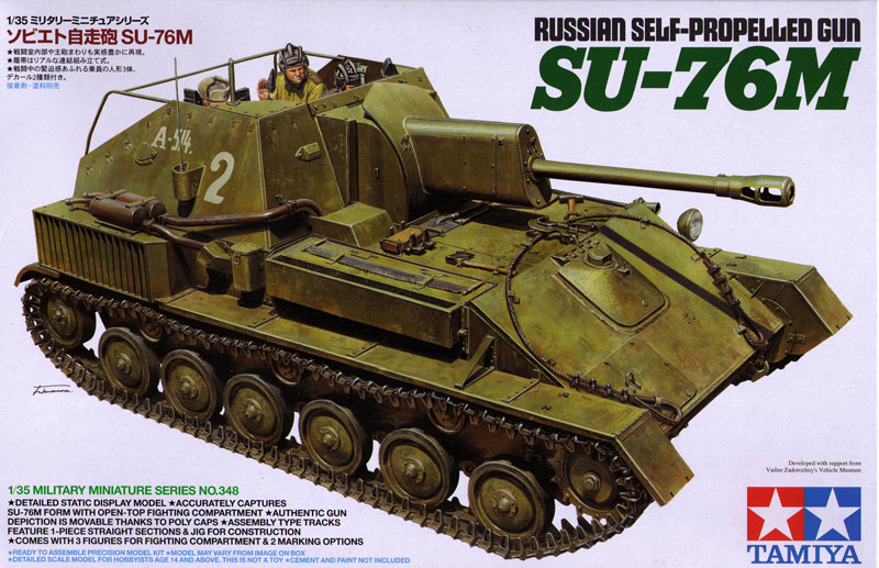
Kicked this one off today and duly started in on Step 1. This is a simple step, it just assembles the base of the gun mount complete with a polycap and gets the hull nose plate ready for install later on in Step 3. I deliberately left off the hook details for now as I prefer to avoid adding details to plates until after they are in place to prevent damage, loss, etc.
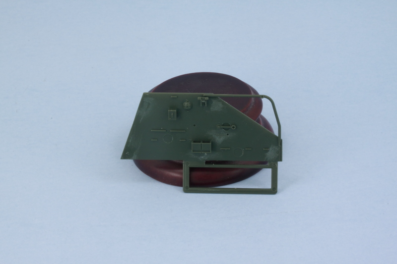
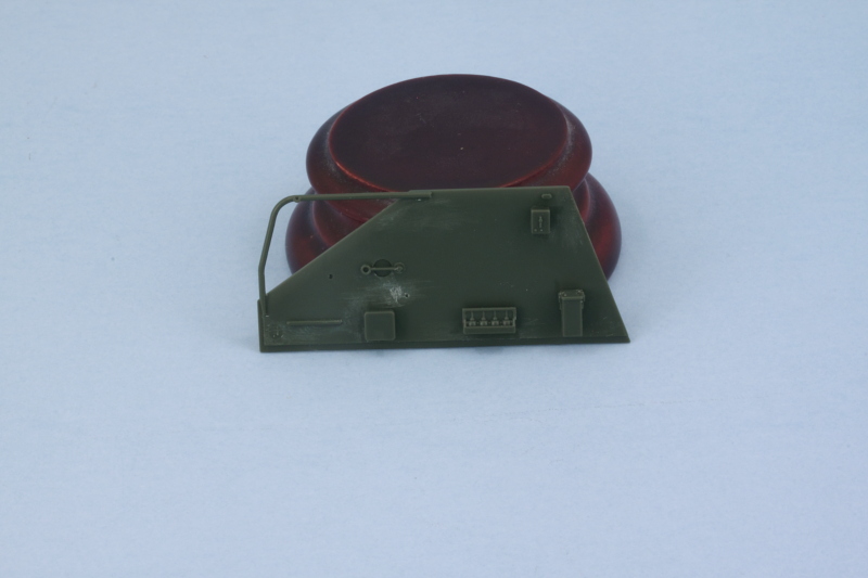
Step 2 builds up the front plate of the fighting compartment. This part does double duty as the main hull support bulkhead, so it plays an important role. First order of business was dealing with the many small ejector marks on the interior face. They aren't deep but some of them are in hard to reach spots. I used some custom cut sanding sticks that keep on hand for just this type of thing and sanded them down. It was only after I sanded smooth the large square area on the right side that I realized it gets covered up completely with additional parts later, but I was in full-on EPM removal mode.
With those taken care of, I completed the assembly as called for in the step.
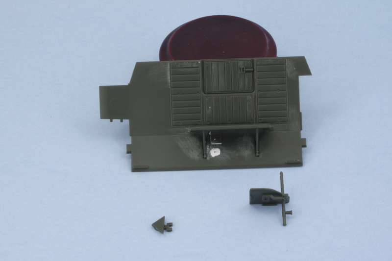
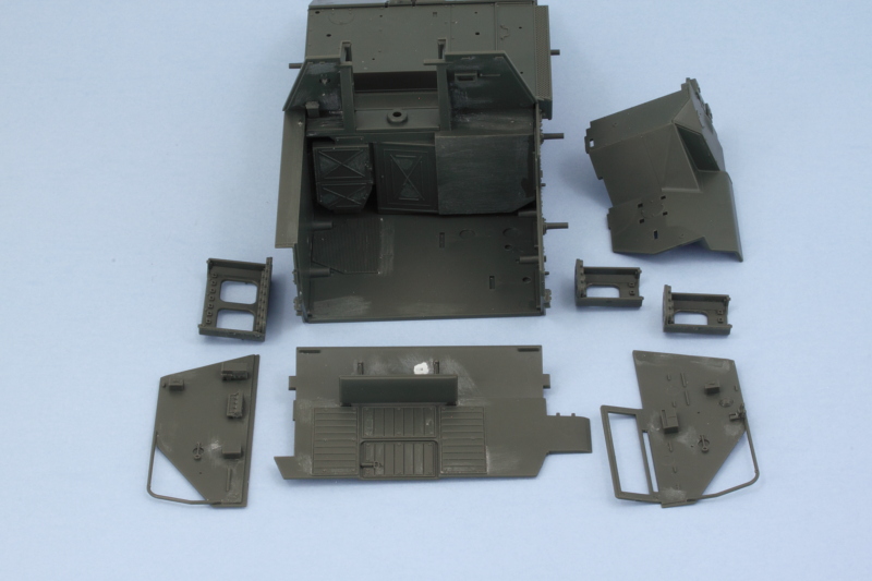
Step 3 deals with the multi-panel hull assembly. I know some have reservations about this type of approach vs. a one-piece tub, but Tamiya did a great job with the fit and engineering here. First up though, you guessed it, more little ejector marks to deal with. Most of these are around the suspension arm mounts and would most likely be covered by the road wheels but I didn't want to take any chances. Others were in highly visible areas and had to go, so more delicate sanding/trimming with a sharp #11 blade did the trick.
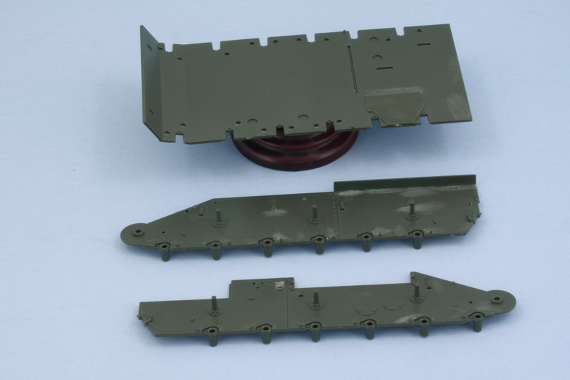
The instructions clearly direct you to assemble the hull in a specific sequence of events to avoid any problems. The nose plate goes on first, then the sides are attached to the floor pan, then the superstructure plate slides in between them to lock it all together. I used liquid glue to attach everything and encountered zero problems in the process.
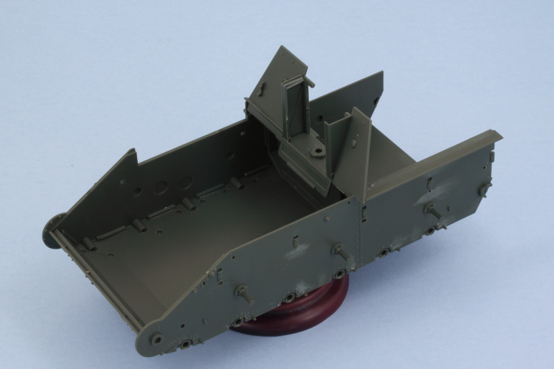
Just to be sure I wouldn't have any problems later on, I skipped ahead to Step 15 and added in the glacis and engine deck plates. There's no real good reason I could see in the instruction order to wait to attach them and it has the added bonus of ensuring the hull would set up square. For good measure, I did a test fit with the compartment back plate, part B8, and held it in place with masking tape. Everything fit like a glove.
So far so good! Once the hull is fully set, I'll circle back and add the details called for to the nose plate and also work on the suspension components. Steps 4-13 deal with the fighting compartment interior and will be skipped for a while until I'm ready to tackle that area given all the detail work it involves.
Step 2 builds up the front plate of the fighting compartment. This part does double duty as the main hull support bulkhead, so it plays an important role. First order of business was dealing with the many small ejector marks on the interior face. They aren't deep but some of them are in hard to reach spots. I used some custom cut sanding sticks that keep on hand for just this type of thing and sanded them down. It was only after I sanded smooth the large square area on the right side that I realized it gets covered up completely with additional parts later, but I was in full-on EPM removal mode.
With those taken care of, I completed the assembly as called for in the step.
Step 3 deals with the multi-panel hull assembly. I know some have reservations about this type of approach vs. a one-piece tub, but Tamiya did a great job with the fit and engineering here. First up though, you guessed it, more little ejector marks to deal with. Most of these are around the suspension arm mounts and would most likely be covered by the road wheels but I didn't want to take any chances. Others were in highly visible areas and had to go, so more delicate sanding/trimming with a sharp #11 blade did the trick.
The instructions clearly direct you to assemble the hull in a specific sequence of events to avoid any problems. The nose plate goes on first, then the sides are attached to the floor pan, then the superstructure plate slides in between them to lock it all together. I used liquid glue to attach everything and encountered zero problems in the process.
Just to be sure I wouldn't have any problems later on, I skipped ahead to Step 15 and added in the glacis and engine deck plates. There's no real good reason I could see in the instruction order to wait to attach them and it has the added bonus of ensuring the hull would set up square. For good measure, I did a test fit with the compartment back plate, part B8, and held it in place with masking tape. Everything fit like a glove.
So far so good! Once the hull is fully set, I'll circle back and add the details called for to the nose plate and also work on the suspension components. Steps 4-13 deal with the fighting compartment interior and will be skipped for a while until I'm ready to tackle that area given all the detail work it involves.
-
Bill Plunk
- Posts: 1245
- Joined: Wed Sep 28, 2022 10:18 pm
WIP 03-19-2016
More progress to report! I went back to Step 1 and duly added in the tow hook arrangments to the nose plate so I wouldn't forget about it later on. Easily done, you just have to be sure to add the small triangular parts, A6, first and then the main hooks to avoid any issues.
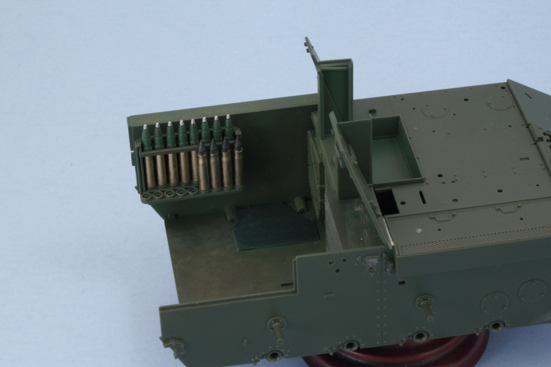
Rather than move on to the suspension as I originally planned, I instead started in on the interior modules to complete what I could there so that it would make painting and assembly easier when I get to that stage. First up, I assembled the main parts of the two right-hand side shell racks as called out in Step 4. The bases have small tabs that extend beyond the rack wall and are used to install them into the fighting compartment, so I wanted to see how easy that would be if the compartment wall itself was already installed.
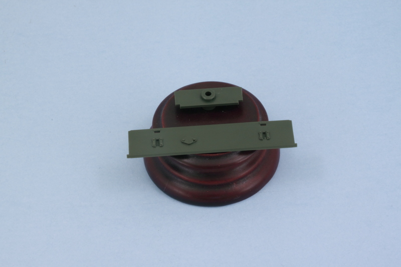
The right side of the compartment is assembled in Step 5 out of two separate large pieces. I used the main hull to help ensure they were lined up properly in relation to each other and the angled front part of the compartment, then carefully applied liquid glue to the join and let it set inside the compartment before popping it out so it would behave as a single piece going forward. A quick test with the shell racks showed that the recommended order in the instructions of installing them to the compartment side first is a good one...it's a pretty tight fit, so I will deal with them separately in the painting and detailing department.
It's also worth noting here that Tamiya did something a little funny with the shell rack components. The retaining clips for each round are molded onto the rounds themselves, so there are no clips present for the empty round places in the racks. Tamiya deliberately left several round places empty in all three racks, so that leaves something for the aftermarket boys or the adventurous scratch-builders to address.
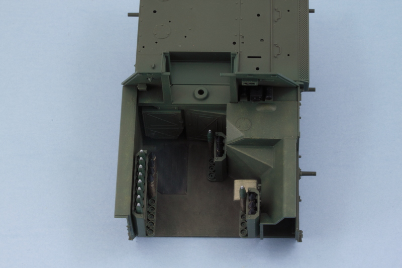
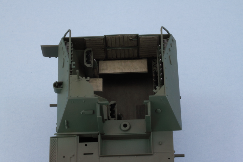
Skipping over to Step 11, I worked on the compartment rear plate. Some ejector marks that would be visible were removed and I installed the bench seat and supports so I could work with this as another interior module for painting.
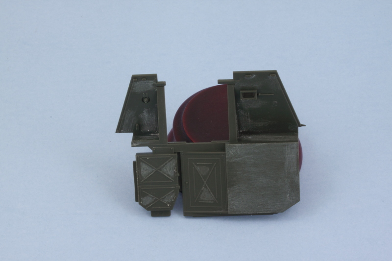
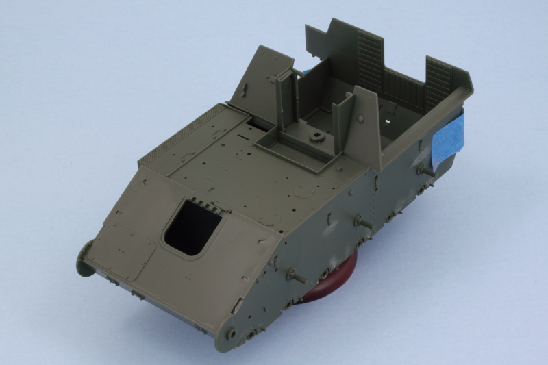
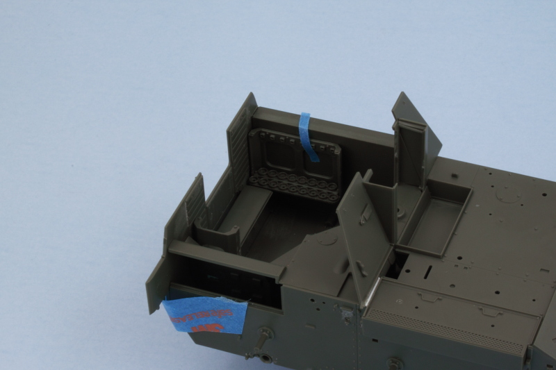
A quick mock-up with some masking tape and poster putty shows just how cramped/tight the interior is with all this stuff. I deliberately left off the little commander's jump seat on the right wall as it will be easier to detail it separately and then install it due to how closely it fits against the rear shell rack.
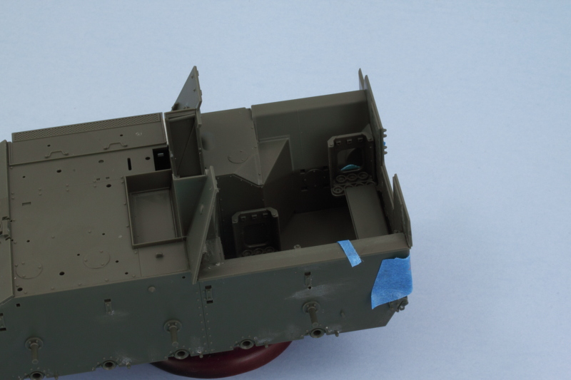
I also noticed that there was a small gap/opening on the right side between the engine deck and the angled superstructure front. As near as I could tell after consulting available reference photos of the actual vehicle, there is supposed to be a small gap here but not one that would extend all the way down into the hull itself. To address that, I added a small length of white styrene rod and applied liquid glue to soften it then shaped it with a wooden toothpick to fill in the base hull area while still leaving the superficial gap between the superstructure and the engine deck area. Not sure if that's 100% accurate, but it looks better to my eye vs. having this small crack down into the interior.
Next up will be spending some time on the fighting compartment upper sides to get them ready for paint.
Rather than move on to the suspension as I originally planned, I instead started in on the interior modules to complete what I could there so that it would make painting and assembly easier when I get to that stage. First up, I assembled the main parts of the two right-hand side shell racks as called out in Step 4. The bases have small tabs that extend beyond the rack wall and are used to install them into the fighting compartment, so I wanted to see how easy that would be if the compartment wall itself was already installed.
The right side of the compartment is assembled in Step 5 out of two separate large pieces. I used the main hull to help ensure they were lined up properly in relation to each other and the angled front part of the compartment, then carefully applied liquid glue to the join and let it set inside the compartment before popping it out so it would behave as a single piece going forward. A quick test with the shell racks showed that the recommended order in the instructions of installing them to the compartment side first is a good one...it's a pretty tight fit, so I will deal with them separately in the painting and detailing department.
It's also worth noting here that Tamiya did something a little funny with the shell rack components. The retaining clips for each round are molded onto the rounds themselves, so there are no clips present for the empty round places in the racks. Tamiya deliberately left several round places empty in all three racks, so that leaves something for the aftermarket boys or the adventurous scratch-builders to address.
Skipping over to Step 11, I worked on the compartment rear plate. Some ejector marks that would be visible were removed and I installed the bench seat and supports so I could work with this as another interior module for painting.
A quick mock-up with some masking tape and poster putty shows just how cramped/tight the interior is with all this stuff. I deliberately left off the little commander's jump seat on the right wall as it will be easier to detail it separately and then install it due to how closely it fits against the rear shell rack.
I also noticed that there was a small gap/opening on the right side between the engine deck and the angled superstructure front. As near as I could tell after consulting available reference photos of the actual vehicle, there is supposed to be a small gap here but not one that would extend all the way down into the hull itself. To address that, I added a small length of white styrene rod and applied liquid glue to soften it then shaped it with a wooden toothpick to fill in the base hull area while still leaving the superficial gap between the superstructure and the engine deck area. Not sure if that's 100% accurate, but it looks better to my eye vs. having this small crack down into the interior.
Next up will be spending some time on the fighting compartment upper sides to get them ready for paint.
-
Bill Plunk
- Posts: 1245
- Joined: Wed Sep 28, 2022 10:18 pm
WIP 03-20-2016
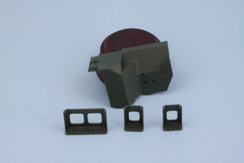
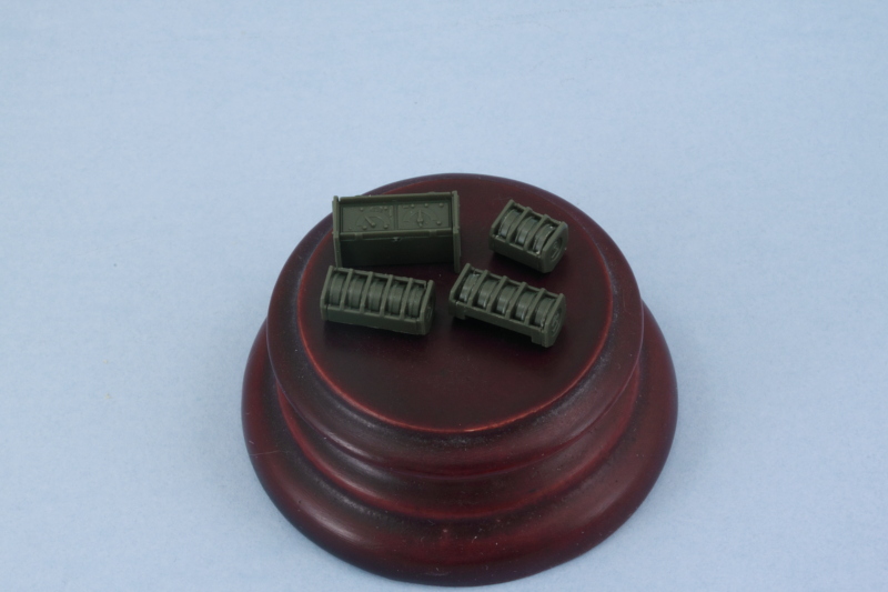
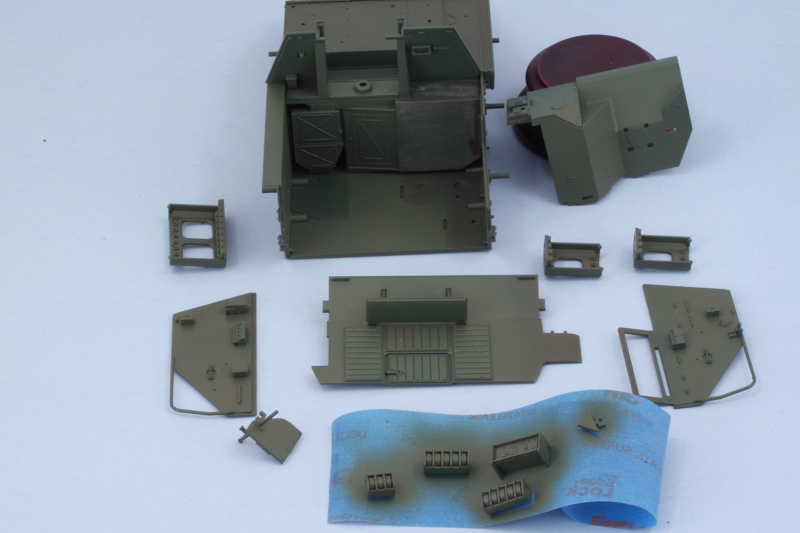
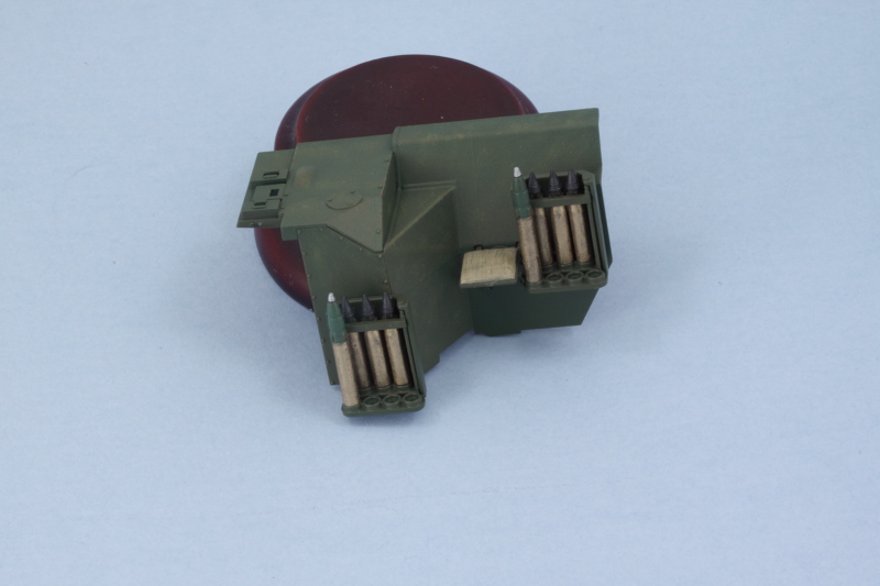
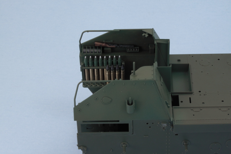
Continuing on with the fighting compartment stuff, I assembled the three sub-machine ammo racks and the radio equipment as called for in Step 7. These will get installed separately after I've had a chance to paint them, two of the racks go on the right side along with the radio and the third one goes on the left side.
Step 8 addresses the right side of the compartment and I removed the ejector marks that would be visible and left the others alone. All of the little details that would be the same hull color were installed to get it squared away.
Step 9 installs the radio and ammo racks, so this was temporarily skipped. Step 10 gives the detail treatment to the left side. Same drill regarding ejector marks here too!
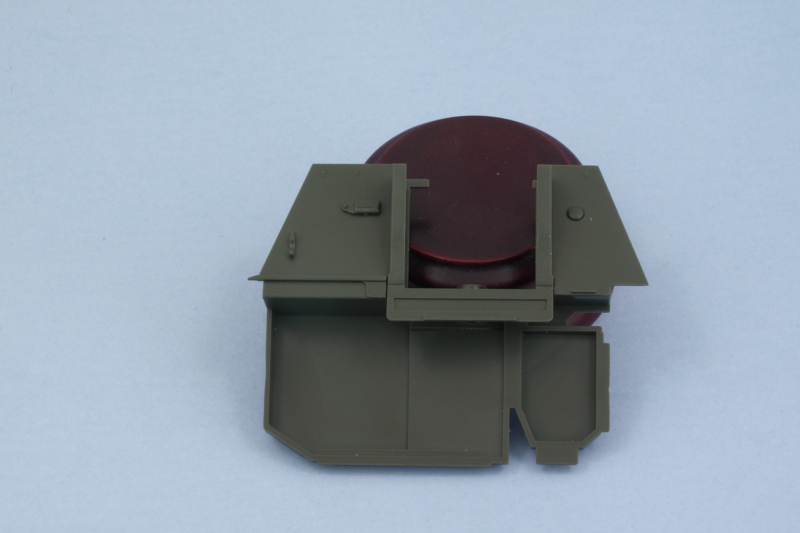
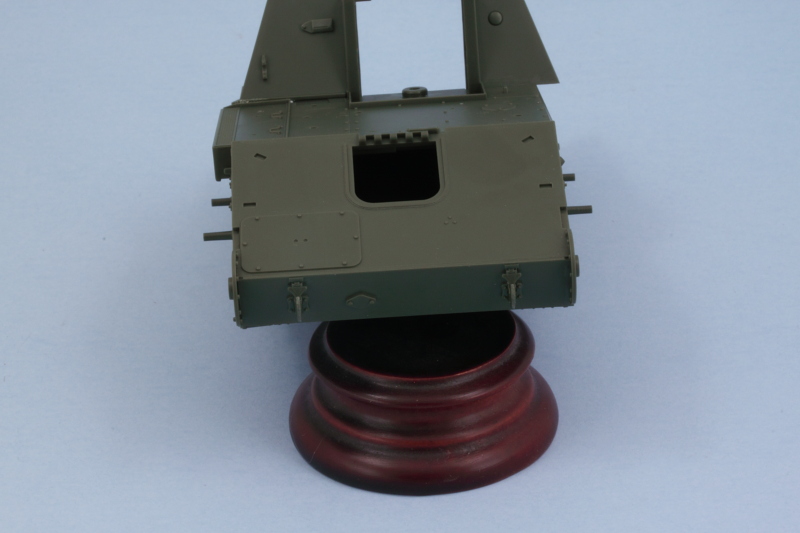
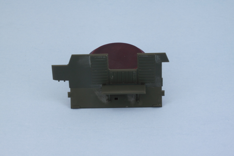
The back plate received some more attention as I decided to go ahead and install its door in the closed position. This isn't called out until the very final step 37 that also addresses the figures...I'm not sure if you need to have the door open in order for one of the crewmen to fit correctly, it's hard to be sure. The instruction diagram's top-down view of how they sit doesn't seem to indicate this would be a problem, but I'm not planning on placing the figures myself so it's not a big deal for me but could be for others. I also added the tow hook components from Step 16 as I wanted to see how much of the opening there would be filled by the hook. Turns out it doesn't completely fill up the space, so I puttied over it to make it seamless with the rest of the interior plate.
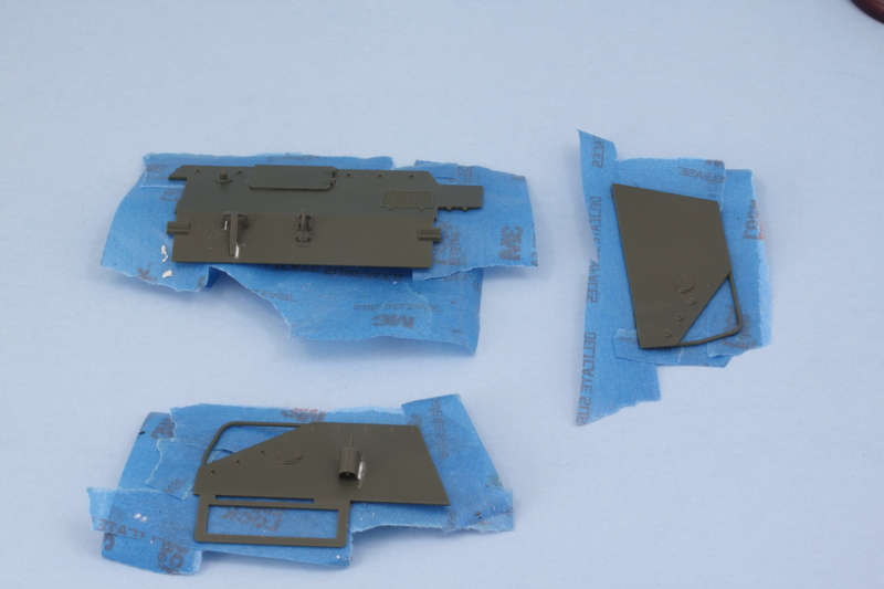
For good measure, I also got the triangular plates that attach to the tops of the fighting compartment ready for paint. These are covered in Step 34. I drilled out the eyepiece face and also drilled an actual hole in the top portion of the pipe periscope. The part has a molded dimple here, I used a #78 micro drill bit to up the detail a touch.
So here's where all the interior parts of the fighting compartment are at before I start in on getting them painted and detailed.
Step 8 addresses the right side of the compartment and I removed the ejector marks that would be visible and left the others alone. All of the little details that would be the same hull color were installed to get it squared away.
Step 9 installs the radio and ammo racks, so this was temporarily skipped. Step 10 gives the detail treatment to the left side. Same drill regarding ejector marks here too!
The back plate received some more attention as I decided to go ahead and install its door in the closed position. This isn't called out until the very final step 37 that also addresses the figures...I'm not sure if you need to have the door open in order for one of the crewmen to fit correctly, it's hard to be sure. The instruction diagram's top-down view of how they sit doesn't seem to indicate this would be a problem, but I'm not planning on placing the figures myself so it's not a big deal for me but could be for others. I also added the tow hook components from Step 16 as I wanted to see how much of the opening there would be filled by the hook. Turns out it doesn't completely fill up the space, so I puttied over it to make it seamless with the rest of the interior plate.
For good measure, I also got the triangular plates that attach to the tops of the fighting compartment ready for paint. These are covered in Step 34. I drilled out the eyepiece face and also drilled an actual hole in the top portion of the pipe periscope. The part has a molded dimple here, I used a #78 micro drill bit to up the detail a touch.
So here's where all the interior parts of the fighting compartment are at before I start in on getting them painted and detailed.
-
Bill Plunk
- Posts: 1245
- Joined: Wed Sep 28, 2022 10:18 pm
WIP 03-21-2016
Managed to get some airbrush work in on the interior. I started with a base coat of Testors Model Master enamel Russian Armor Green. This did double-duty as a primer coat and let me check all my sanding to see if everything was going in the right direction.
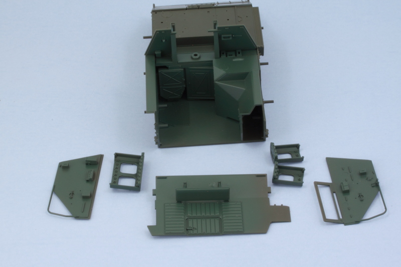
I've never been quite happy with this particular color right out of the bottle, it's got a kind of 'minty' green hint to it, so I tried something a little different. I mixed up a custom color using a 50/50 ratio of the MM enamel Russian Armor Green and Olive Drab FS34087. This was sprayed at low pressure over the previous coat to build up the finish. As an unintended side effect, I think I might have come up with a pretty close match to the kit's original plastic color. It's also hard to photograph it accurately, but in hand it came out along the lines I was after.
Now to let that cure a little bit and then start in on the actual detailing and weathering of the interior so I can get it all together.
I've never been quite happy with this particular color right out of the bottle, it's got a kind of 'minty' green hint to it, so I tried something a little different. I mixed up a custom color using a 50/50 ratio of the MM enamel Russian Armor Green and Olive Drab FS34087. This was sprayed at low pressure over the previous coat to build up the finish. As an unintended side effect, I think I might have come up with a pretty close match to the kit's original plastic color.
Now to let that cure a little bit and then start in on the actual detailing and weathering of the interior so I can get it all together.
-
Bill Plunk
- Posts: 1245
- Joined: Wed Sep 28, 2022 10:18 pm
WIP 03-22-2016
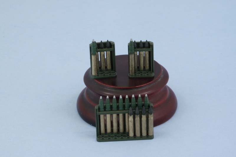
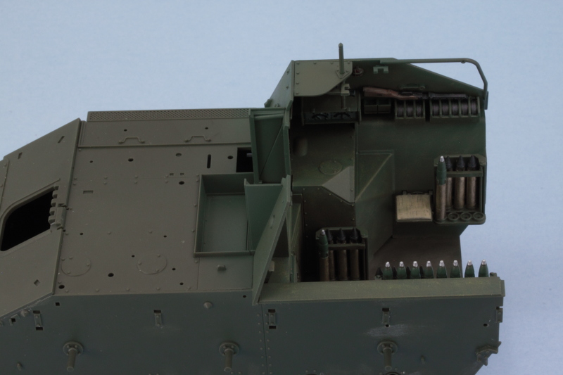
First important detail for the interior is the ammo racks, so today's efforts were split between Steps 4 and 12 in the instructions. The kit provides 10 AP rounds and 10 HE rounds that are designed to go in the racks proper and an additional 4 AP and 4 HE 'whole' rounds that don't have the clips molded on them and have the full casing base. At first, I thought this was kind of strange as the racks have 11 empty spaces leaving one space totally unaccounted for. Why so many empty spaces? After studying the layout of the crew figures in the Step 37 diagram, I think I know why. If the racks were fully loaded up, the loader figure doesn't have enough room for sure and there might also be a conflict with the commander figure on the other side. It's a cramped space and figures aren't flexible, so I suppose it was a necessary compromise on Tamiya's part. It also explains the missing clips as the figures would fill up that space. If you don't use the figures, that's a different story!
Anyhow, I cleaned up all 20 of the rounds I needed to go into the racks and then hand painted them. I used MM Non-buffing metalizer Brass for the casings, non-buffing metalizer Gunmetal for the AP rounds, enamel Italian Olive Green for the HE rounds, and non-buffing metalizer Steel for the HE fuse caps.
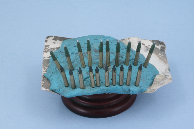
The back row of rounds went into the racks first, then the support rack for the front row added and painted to match the rest of the rack. Last but not least, the partial front row loads were added to get the racks together.
Still plenty left to do with the interior!
Anyhow, I cleaned up all 20 of the rounds I needed to go into the racks and then hand painted them. I used MM Non-buffing metalizer Brass for the casings, non-buffing metalizer Gunmetal for the AP rounds, enamel Italian Olive Green for the HE rounds, and non-buffing metalizer Steel for the HE fuse caps.
The back row of rounds went into the racks first, then the support rack for the front row added and painted to match the rest of the rack. Last but not least, the partial front row loads were added to get the racks together.
Still plenty left to do with the interior!
-
Bill Plunk
- Posts: 1245
- Joined: Wed Sep 28, 2022 10:18 pm
WIP 03-24-2016
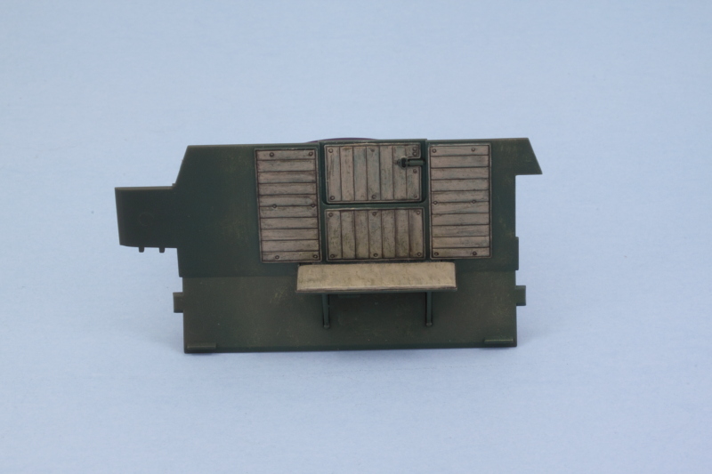
More fun with the interior over the past couple of days. Next up I spent some time on the rear plate. The color call-out in the instructions is for Tamiya's XF-49 Khaki, so I set about replicating that as best I could using a combination of a base color of 50/50 MM enamel Light Gray/Afrika Grunbraun followed by a wash of Ammo's Interior's Wash (because it has a kind of greenish tint to it) and dry-brushing some of the 50/50 Russian Armor Green/Olive Drab combo. Then a pin wash of Ammo's Africa Korps Wash to add some depth and it was about where I wanted it. Given the whole reason for the upholstered padding as a way to keep the crew from banging their elbows/knees, etc. on the armor plating in the tight space, I doubt it stayed 'new car' looking for long.
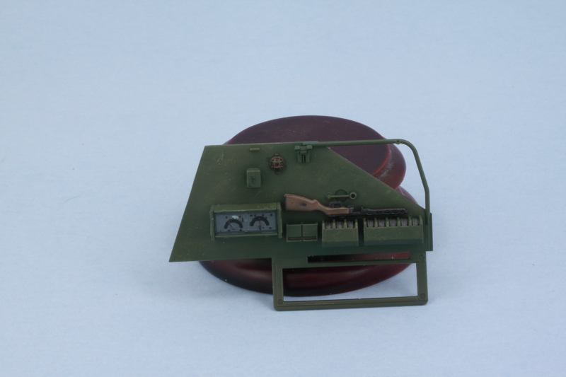
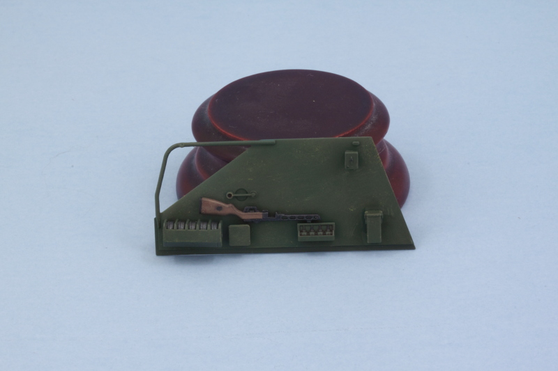
Side panels got some attention next, starting on the right side. On all of the panels and compartment areas, I added some scuffing/wear in the form of some dry-brushed MM enamel Deep Yellow followed by a 2nd round of dry-brushed 80/20 Olive Drab/Russian Armor Green to vary the tones a bit. The radio was detailed by hand along with the PPSH submachine gun. The gun's barrel is molded solid, so I drilled it out with a #76 micro drill. The drum magazines were picked out with MM non-buffing Metalizer gunmetal. Last but not least, I picked out the compartment's night light with Tamiya Clear Red.
Rinse and repeat for the left side!
For the compartment's floor, I detailed the rubber kneeling mat for the gunner with MM enamel Gunmetal. I went heavier in the wear here for obvious reasons and used multiple layers. First some Deep Yellow was stippled and dry-brushed, followed by stippled and dry-brushed enamel Burnt Umber. Then the 50/50 OD/Russian Green was dry-brushed and a final overall wash of Ammo Interior Wash to round it out.
The right side lower wall got some attention as well with the installation of the commander's jump seat and the two ammo racks. I still need to detail and add in the rest of the radio's power supply equipment, I ran out of time today before I could get to it. The left side of the compartment got the large rack installed as well to call it a day.
Still a few small things to do in the compartment but it's just about ready to get it all together.
Side panels got some attention next, starting on the right side. On all of the panels and compartment areas, I added some scuffing/wear in the form of some dry-brushed MM enamel Deep Yellow followed by a 2nd round of dry-brushed 80/20 Olive Drab/Russian Armor Green to vary the tones a bit. The radio was detailed by hand along with the PPSH submachine gun. The gun's barrel is molded solid, so I drilled it out with a #76 micro drill. The drum magazines were picked out with MM non-buffing Metalizer gunmetal. Last but not least, I picked out the compartment's night light with Tamiya Clear Red.
Rinse and repeat for the left side!
For the compartment's floor, I detailed the rubber kneeling mat for the gunner with MM enamel Gunmetal. I went heavier in the wear here for obvious reasons and used multiple layers. First some Deep Yellow was stippled and dry-brushed, followed by stippled and dry-brushed enamel Burnt Umber. Then the 50/50 OD/Russian Green was dry-brushed and a final overall wash of Ammo Interior Wash to round it out.
The right side lower wall got some attention as well with the installation of the commander's jump seat and the two ammo racks. I still need to detail and add in the rest of the radio's power supply equipment, I ran out of time today before I could get to it.
Still a few small things to do in the compartment but it's just about ready to get it all together.
-
Bill Plunk
- Posts: 1245
- Joined: Wed Sep 28, 2022 10:18 pm
WIP 03-25-2016
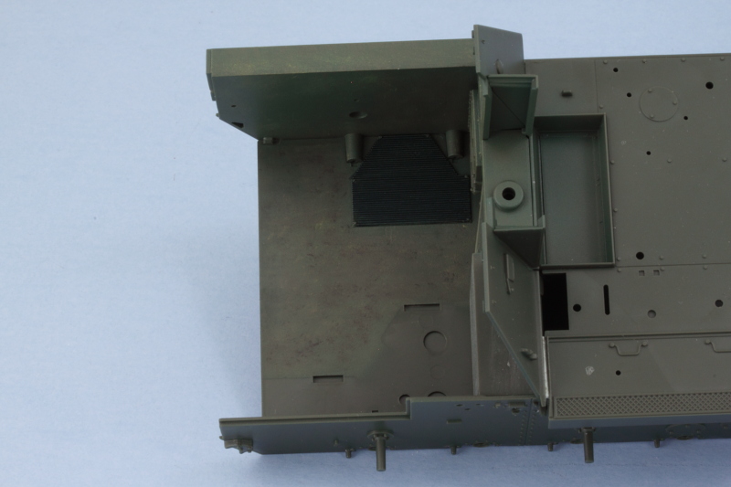
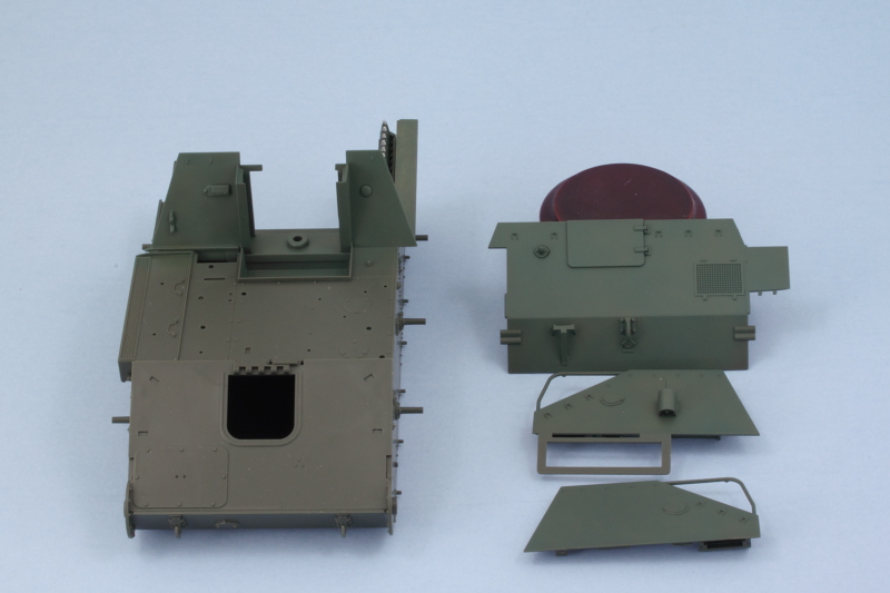
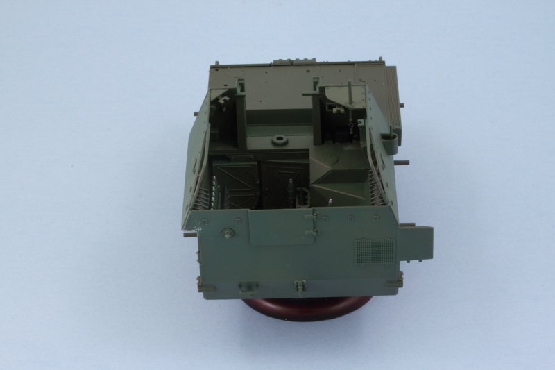
Achieved a major milestone in the build today in terms of getting the fighting compartment all together. First order of business, I decided it would be easier to paint the exterior of the compartment plates before installation. This meant adding some of the exterior details like the crew step called out in Step 18 and the radio antenna and pot called out in Step 21. Both of those parts have recessed mount points and a little bit of putty help was needed in some spots to fill those in completely before painting.
The plates and the front of the compartment were airbrushed first with Russian Armor Green and followed up with the 50/50 OD/Russian Armor Green treatment that I used on the interior.
I installed the rest of the communications equipment on the right side and added the large wall component into the compartment proper. While I still had the compartment open, I added some pigment weathering in the form of Mig Rubble Dust applied to the floor.
Right side upper plate was added next along with the large top plate that includes the commander's periscopes. It has the added advantage of a larger attachment area due to the radiator box that attaches to the outside, so it was the easiest to get lined up with the front of the compartment.
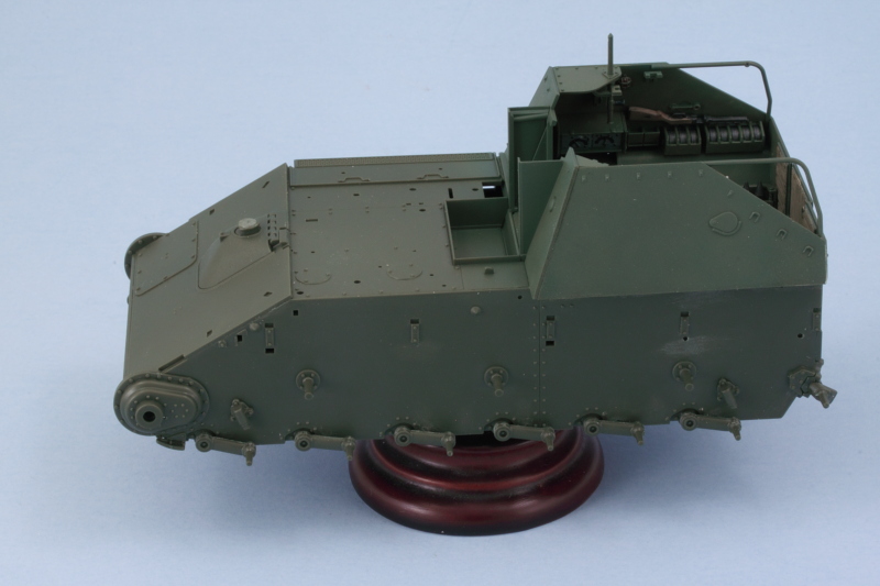
For the left side, I used regular glue along the base edge since it has the most contact surface and liquid glue at the front once it had grabbed a bit. As you can see in the photos, the greens don't all match up perfectly just yet, that will change once it's all set and I have the opportunity to go back over the join areas with the airbrush. My main concern at this point was avoiding having to do a lot of work with the full compartment masked off.
Last but not least, the rear plate was added to complete the full compartment. Overall the fit was excellent. One small minor area on the left rear plate join needed just a touch of putty and sanding, otherwise it all went together perfectly.
Next up will be spending some time on the suspension components and various other external details.
The plates and the front of the compartment were airbrushed first with Russian Armor Green and followed up with the 50/50 OD/Russian Armor Green treatment that I used on the interior.
I installed the rest of the communications equipment on the right side and added the large wall component into the compartment proper. While I still had the compartment open, I added some pigment weathering in the form of Mig Rubble Dust applied to the floor.
Right side upper plate was added next along with the large top plate that includes the commander's periscopes. It has the added advantage of a larger attachment area due to the radiator box that attaches to the outside, so it was the easiest to get lined up with the front of the compartment.
For the left side, I used regular glue along the base edge since it has the most contact surface and liquid glue at the front once it had grabbed a bit. As you can see in the photos, the greens don't all match up perfectly just yet, that will change once it's all set and I have the opportunity to go back over the join areas with the airbrush. My main concern at this point was avoiding having to do a lot of work with the full compartment masked off.
Last but not least, the rear plate was added to complete the full compartment. Overall the fit was excellent. One small minor area on the left rear plate join needed just a touch of putty and sanding, otherwise it all went together perfectly.
Next up will be spending some time on the suspension components and various other external details.
-
Bill Plunk
- Posts: 1245
- Joined: Wed Sep 28, 2022 10:18 pm
WIP 03-26-2016
As promised, today's efforts focused on getting the suspension components installed and ready for painting. To do this, I had to go back to Step 3 and add the final drive housings along with their polycaps. I also cleaned up the 6 return rollers since they are called out in the same step, more on them later. Continuing on, Steps 13 and 15 have the 4 bump stops, two per side. That brings us to the main attraction, Step 16, which installs all swing arms and the idler mounts. Tamiya designed the swing arms to be fixed and level with each other using a small mount pin that the arms attach to. This, of course, is also designed to support their link-and-length track arrangement covered in Steps 19-20.
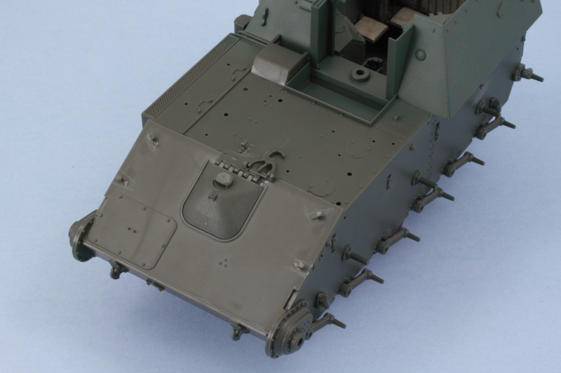
While I was poking around in the steps, I went ahead and added in the driver's hatch and periscope in the closed position. The kit parts have detail on the lower part of the periscope but nothing on the inside face of the hatch or the driver's area.
Road wheels were next under Step 17. There are 14 wheels (6 road, 1 idler per side) that have to be removed from the sprue along with a matching 14 rear hub inserts to make the full wheels. I used a sanding stick to remove the mold seam on the rubber portion of the wheels. Each of the hub inserts has 2 sprue attachment points that have to be carefully removed to keep their round shape intact, easily done with a sharp #11 blade and a little patience.
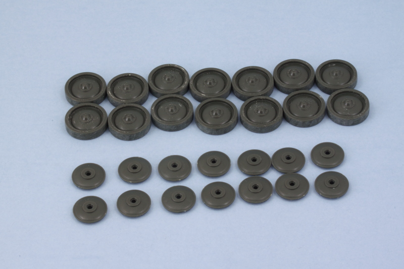
A touch of liquid glue around the rim edges got the wheels together and I also assembled the sprockets as called for in the same step. The steel return rollers from Step 3 also had a small mold seam that was sanded down to get them cleaned up.
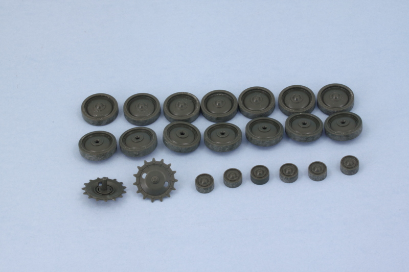
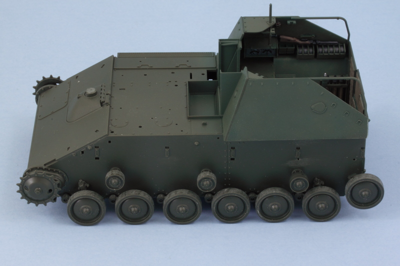
After the glue had dried on the sprockets and wheels, I did a quick test fit to make sure everything sits level and plays nice with each other. As you can see, the road wheels cover almost the whole lower hull area below the fenders. These will be painted separately to allow for easier detailing and weathering before the tracks and fenders have to go on.
Next up will be dealing with some more of the hull details and getting the fenders together so I can maximize the airbrush time for the next round of painting.
While I was poking around in the steps, I went ahead and added in the driver's hatch and periscope in the closed position. The kit parts have detail on the lower part of the periscope but nothing on the inside face of the hatch or the driver's area.
Road wheels were next under Step 17. There are 14 wheels (6 road, 1 idler per side) that have to be removed from the sprue along with a matching 14 rear hub inserts to make the full wheels. I used a sanding stick to remove the mold seam on the rubber portion of the wheels. Each of the hub inserts has 2 sprue attachment points that have to be carefully removed to keep their round shape intact, easily done with a sharp #11 blade and a little patience.
A touch of liquid glue around the rim edges got the wheels together and I also assembled the sprockets as called for in the same step. The steel return rollers from Step 3 also had a small mold seam that was sanded down to get them cleaned up.
After the glue had dried on the sprockets and wheels, I did a quick test fit to make sure everything sits level and plays nice with each other. As you can see, the road wheels cover almost the whole lower hull area below the fenders. These will be painted separately to allow for easier detailing and weathering before the tracks and fenders have to go on.
Next up will be dealing with some more of the hull details and getting the fenders together so I can maximize the airbrush time for the next round of painting.
-
Bill Plunk
- Posts: 1245
- Joined: Wed Sep 28, 2022 10:18 pm
WIP 03-27-2016
Hope everyone had a Happy Easter (for those that it applies...otherwise, Happy Sunday!)
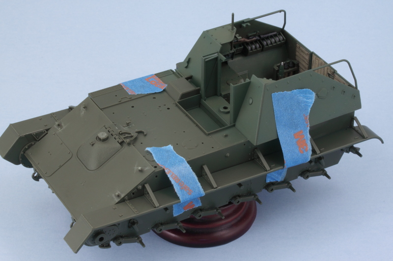
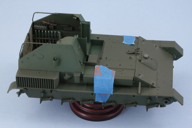
With the focus on getting the hull ready for painting, I bounced around in the instructions quite a bit hunting for stuff that I could install now vs. later. In Step 20, I added the base parts for the gun travel lock while the lock itself is added in Step 24. The lock remains movable, so that's a plus. I also added the small rectangular hood for the exhausts after a test fit showed it's possible to still add the exhaust pipe after it's in place. Step 25 had the 5 retaining hooks for the tow cable, so those were added as well.
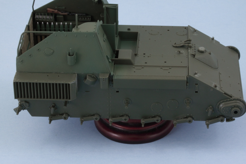
Over on the hull's right side, I added the large radiator/air exhaust box that's called for in Step 21. I found it easier to add the top part, B11, to the hull first since it has a large mount tab to support and align it and then add the rest of the box around it vs. assembling the box off the vehicle and installing it as a single part as the instructions call for. The top doesn't have any solid alignment guides for the 'finned' side portion and getting it lined up right is critical, hence my 'alternative' method to ensure that happened. I added the small canister from Step 23 and the second exhaust cover from Step 24 after again testing the exhaust pipe fit to be sure I could still install it with the cover in place.
Now came the fenders. In order to fit the tracks onto the suspension, the fenders need to remain loose. In theory, since all of the top links are individual links, you could add them after the fenders are in place but that's an iffy proposition at best IMHO. Step 22 assembles the two fenders along with the front portions of the mud guards.
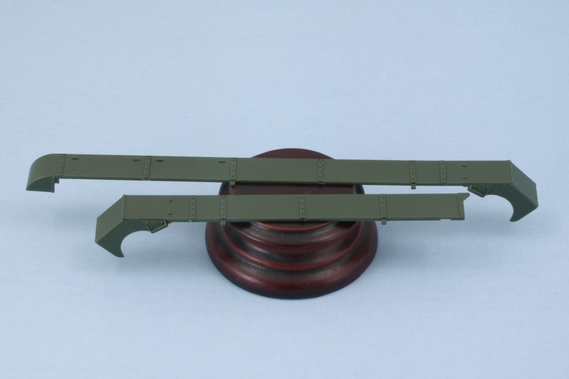
The next trick with the fenders is getting the braces added. Instead of providing the triangular brackets as single pieces, Tamiya molded parts of the bracket on the fenders, part on the hull, and has the angled top part as a single piece that's added to complete the whole bracket. These are added in Steps 24 and 25 and this arrangement actually works out ok if you're careful. I used tape to hold the fenders in place and added the brace tops one at a time and only glued their bottom ends to the fenders themselves. the tops were adjusted so they would fit into the openings in the hull but still allow me to remove the fenders for painting and the track install.
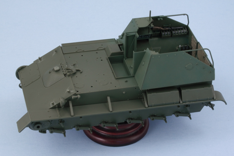
Once I was sure the braces would behave, I added the two storage boxes to the left fender as called out in Step 36. These boxes don't attach to the hull side and the instructions show a nice little sub-diagram that emphasizes this to avoid any mistake. I also cleaned up the headlight and siren horn as mentioned in Step 35 and installed them as directed in Step 36.
That should put me in good shape to get the hull painted before I move on to the gun.
With the focus on getting the hull ready for painting, I bounced around in the instructions quite a bit hunting for stuff that I could install now vs. later. In Step 20, I added the base parts for the gun travel lock while the lock itself is added in Step 24. The lock remains movable, so that's a plus. I also added the small rectangular hood for the exhausts after a test fit showed it's possible to still add the exhaust pipe after it's in place. Step 25 had the 5 retaining hooks for the tow cable, so those were added as well.
Over on the hull's right side, I added the large radiator/air exhaust box that's called for in Step 21. I found it easier to add the top part, B11, to the hull first since it has a large mount tab to support and align it and then add the rest of the box around it vs. assembling the box off the vehicle and installing it as a single part as the instructions call for. The top doesn't have any solid alignment guides for the 'finned' side portion and getting it lined up right is critical, hence my 'alternative' method to ensure that happened.
Now came the fenders. In order to fit the tracks onto the suspension, the fenders need to remain loose. In theory, since all of the top links are individual links, you could add them after the fenders are in place but that's an iffy proposition at best IMHO. Step 22 assembles the two fenders along with the front portions of the mud guards.
The next trick with the fenders is getting the braces added. Instead of providing the triangular brackets as single pieces, Tamiya molded parts of the bracket on the fenders, part on the hull, and has the angled top part as a single piece that's added to complete the whole bracket. These are added in Steps 24 and 25 and this arrangement actually works out ok if you're careful. I used tape to hold the fenders in place and added the brace tops one at a time and only glued their bottom ends to the fenders themselves. the tops were adjusted so they would fit into the openings in the hull but still allow me to remove the fenders for painting and the track install.
Once I was sure the braces would behave, I added the two storage boxes to the left fender as called out in Step 36. These boxes don't attach to the hull side and the instructions show a nice little sub-diagram that emphasizes this to avoid any mistake. I also cleaned up the headlight and siren horn as mentioned in Step 35 and installed them as directed in Step 36.
That should put me in good shape to get the hull painted before I move on to the gun.