Tamiya Russian Self-Propelled Gun SU-76M (2016)

Bill Plunk
Posts: 1245
Joined: Wed Sep 28, 2022 10:18 pm

WIP 03-28-2016

Post by Bill Plunk »

Spent some time on the hull with the airbrush today. First order of business involved masking off the fighting compartment so I could touch up things a bit and blend stuff together. I applied a base coat of MM enamel Russian Armor Green to the hull. I used some blue tack poster putty to hold the fenders in place and get an idea of where the shadowed areas would be.

Image

Road wheels, idlers, and sprockets got some attention as well. I airbrushed MM enamel Gunmetal for the rubber portions then used a circle template to mask the hubs. The Russian Armor Green base coat was airbrushed first followed by a 50/50 mix of OD/Russian Armor Green to get it to the desired color to go with the rest of the hull.

Image

Speaking of which, I used the 50/50 OD/Russian Armor Green mix to shift the color tone of the base coat and provide some variation in the overall look. This was applied at low pressure, approximately 10 psi, and working section by section up close. The fenders were popped off and worked on separately, one nice advantage to having them remain loose until after the tracks are on.

Image

I dry fitted the fenders and removed the masking tape from the compartment to be sure that everything was looking like it all belonged on the same vehicle. I made a couple of small adjustments in a couple spots. Here's where things stand before I start on the gun.

Image

Still plenty to do!
Bill Plunk
Posts: 1245
Joined: Wed Sep 28, 2022 10:18 pm

WIP 03-29-2016

Post by Bill Plunk »

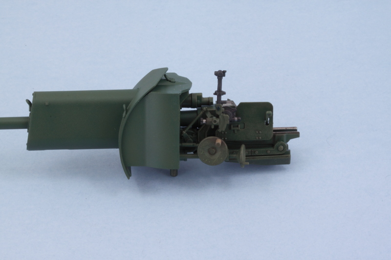
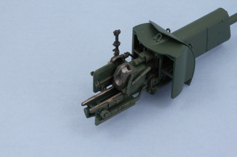
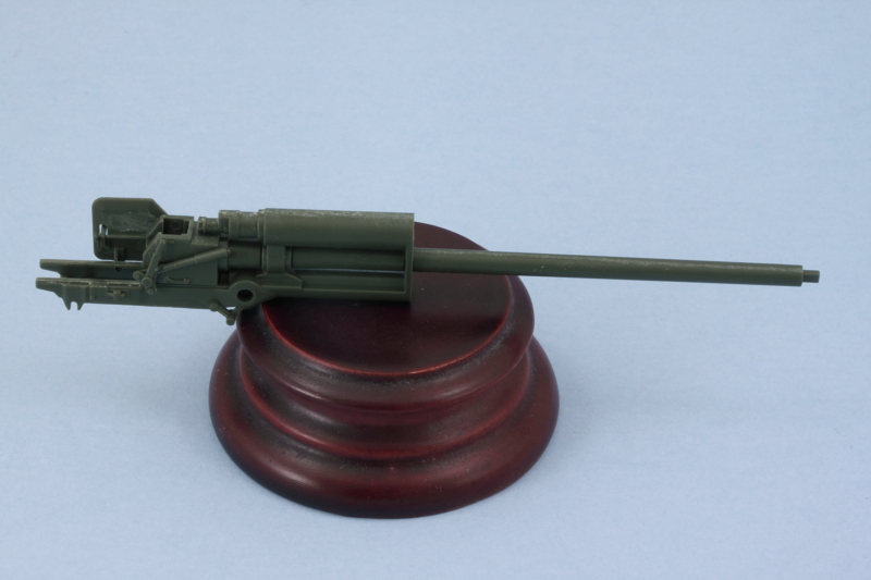
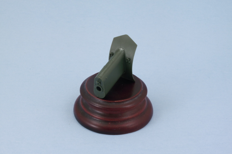
It was finally time to tackle the main event, ZiS-3 76.2mm gun. There are 6 steps in the instructions devoted to getting it together. Starting in Step 26, the three-part breech is assembled and added to the main gun barrel. The step also adds the breech block but I left it off, for now, to make it easier to paint and detail it later. The parts go together nicely with just a little bit of sanding necessary to get the joins to disappear.

Image

Step 27 adds the recoil mechanisms and slide tray. A polycap goes in between the recoil portions and is what allows the gun to hold its position and remain elevatable. The recoil guard had some small ejector marks that needed to be removed on its inside face and I also added the block activation lever mechanism as called for. This can only be positioned one way, with the block closed, due to the use of 2 locating pins to get it in the right spot.

Image

Step 28 continues the assembly with the addition of the side supports for the gun mount and the mount post that supports the gun in the hull. It also adds the part of the gun under the recoil tray that includes the rear part of the travel lock.

Image

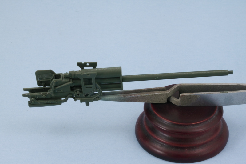
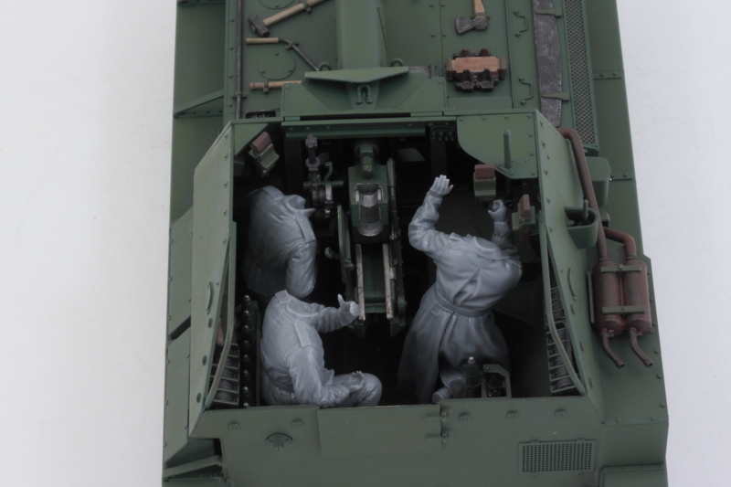
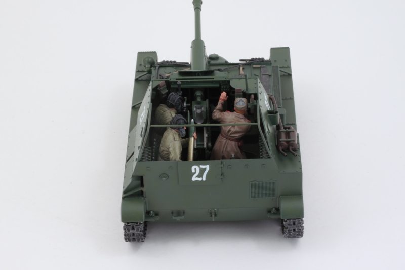
Step 29 is a fairly simple one, it adds the small support tabs for the mantlet sides as well as the elevation and traverse mechanisms along with their hand wheels. I left the wheels off for the time being to make it easier to paint the gun and its details and will add them later. It's also important to note here that the smaller wheel, C77, has to be positioned just so in order for the gunner's hand to match up with it if you plan to use the kit-supplied figures. The instructions include a little 'note direction' callout to help with this but it's not an exact thing to try to eyeball without the gunner already built to help you out. :) I also left off the gunner's sight but will add that later on.

Image

Step 30 adds the sides and top of the armored mantlet for the gun. I used a little bit of finger pressure to flex the sides in just a touch to mate up properly with the top and applied liquid glue so it would grab and create a solid join.

Image

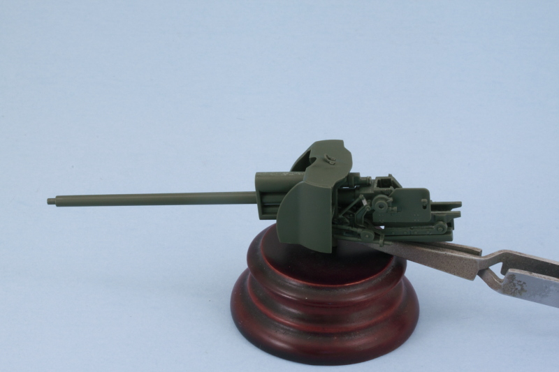
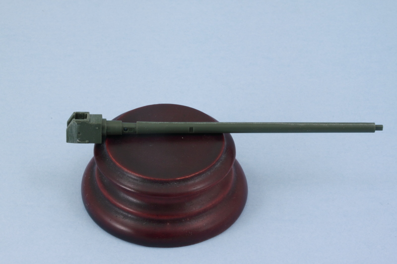
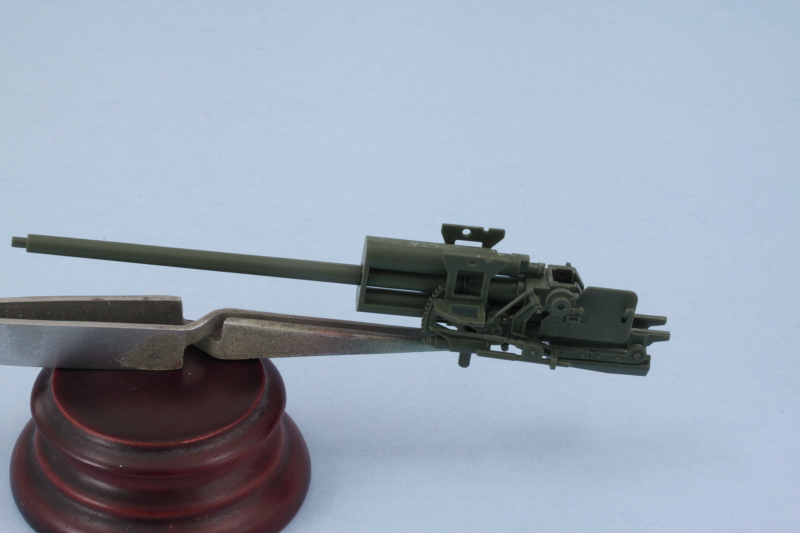
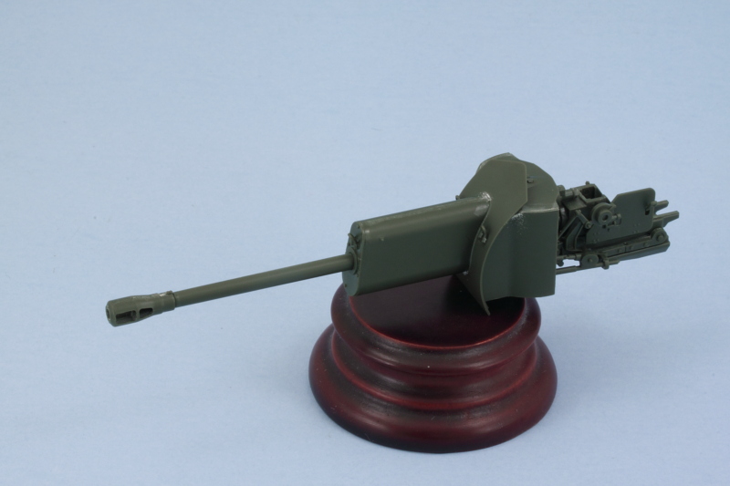
Step 31 assembles the external armored covers for the recoil mechanism and the front plate for the mantlet. I assembled the two halves of the cover first, then added the front plate, then added it all to the mantlet front plate. Just a tiny amount of putty was needed at the top to close up a small gap with the weld seam that's molded on the mantlet front plate.

Image

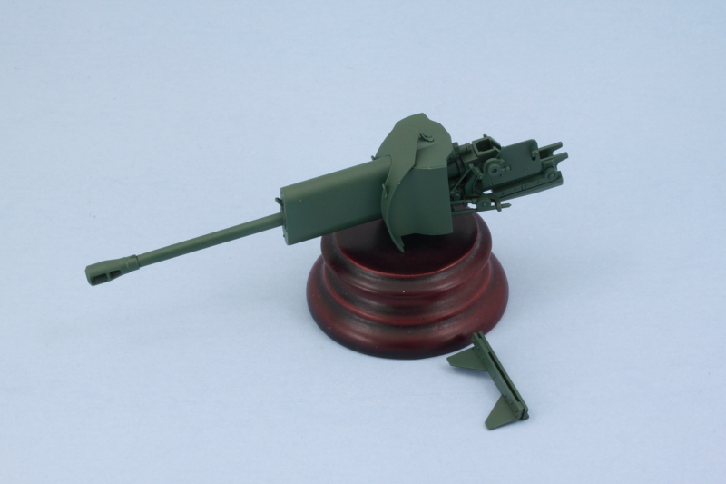
The step also calls for the assembly of the muzzle brake. This is a split-half arrangement, but careful use of liquid glue and some light sanding took care of the small join seam. The recoil cover and mantlet front aren't meant to be glued onto the gun and instead rely on a tight friction fit to keep it in place while still allowing the gun to elevate. The instructions give you a heads-up on this by clearly telling you NOT to glue the curved plate to the rest of the mantlet structure.

Image

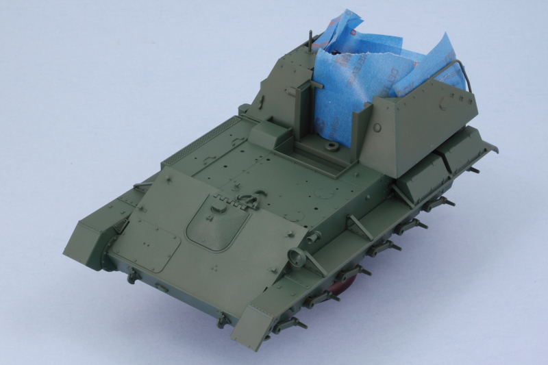
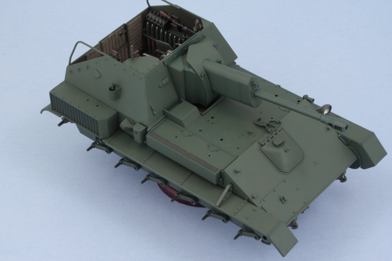
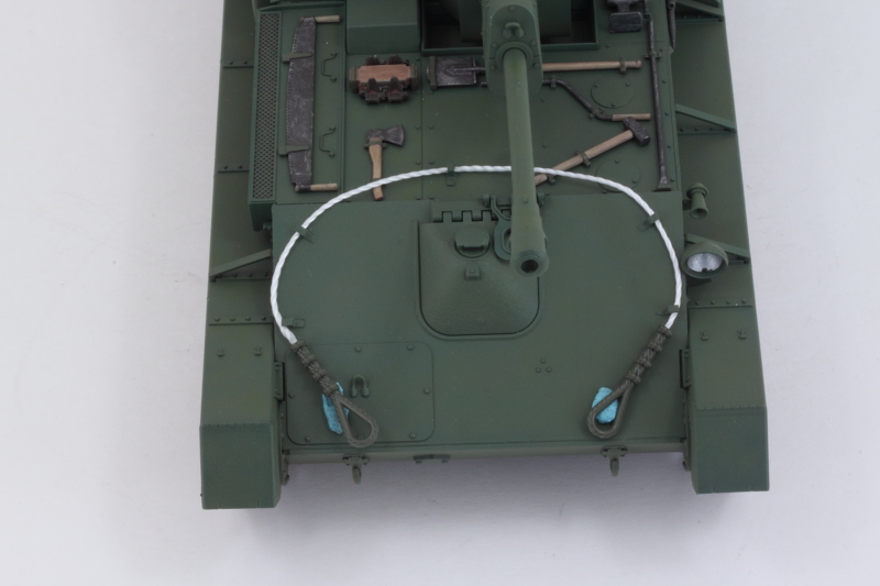
Step 33 has you install the gun into place using the polycap and that also allows you to pull the gun in and out for test fitting before committing to the final installation. Step 35 assembles the mantlet top armor that locks the gun into place out of 3 different pieces that all fit together to create the spaced plate arrangement. A quick check with the gun shows everything lining up like it should. It also showed me that I had missed one of the lifting eyes on the engine access hatch on the front hull, so that got checked off while I was at it.

Image

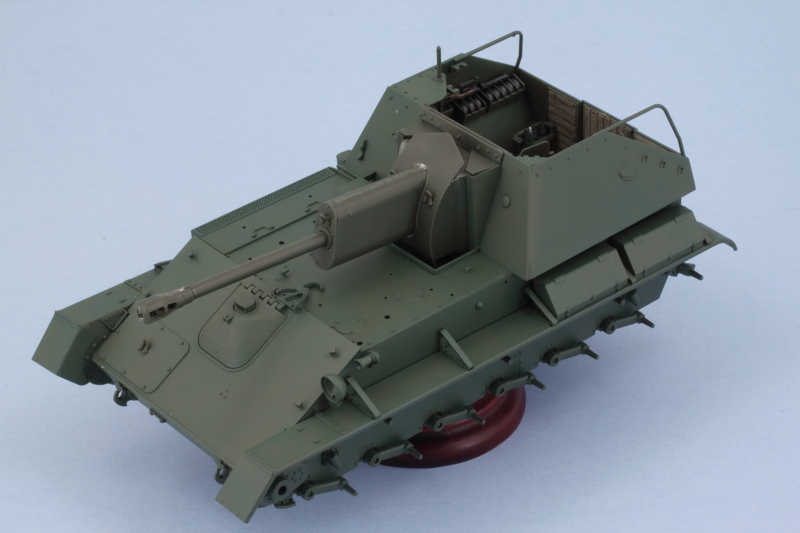
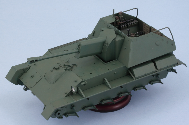
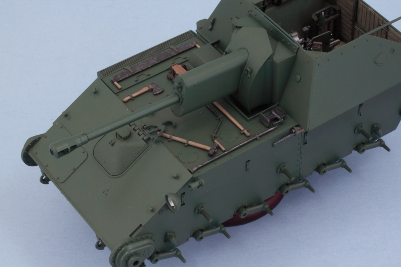
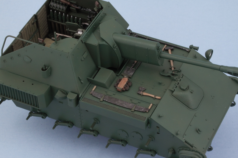
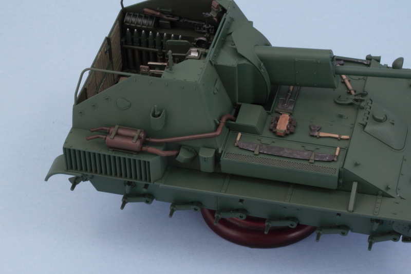
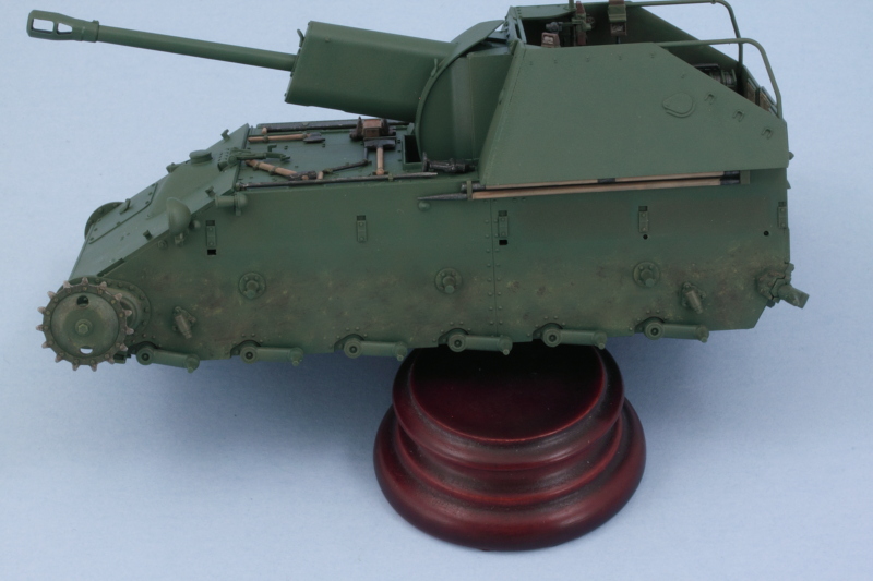
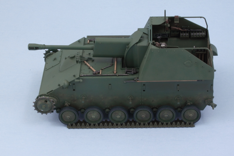
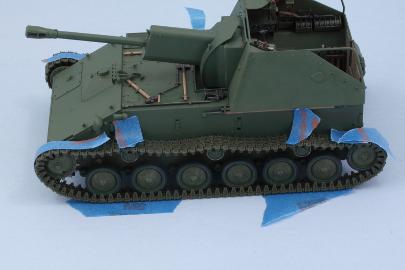
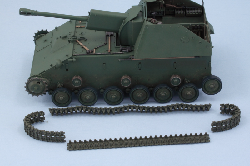
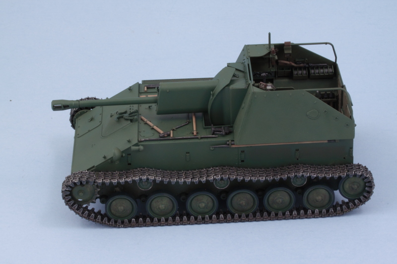
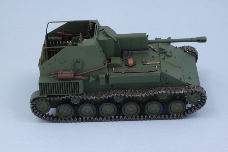
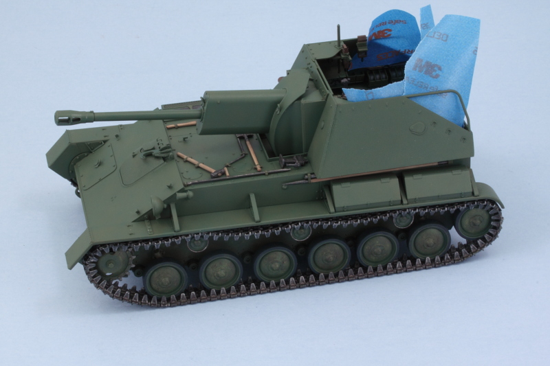
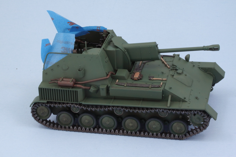
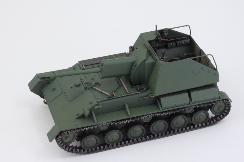
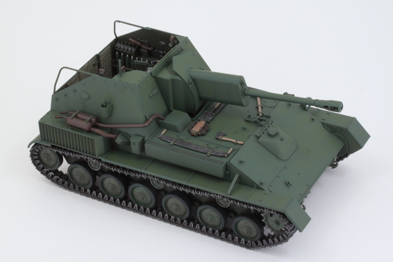
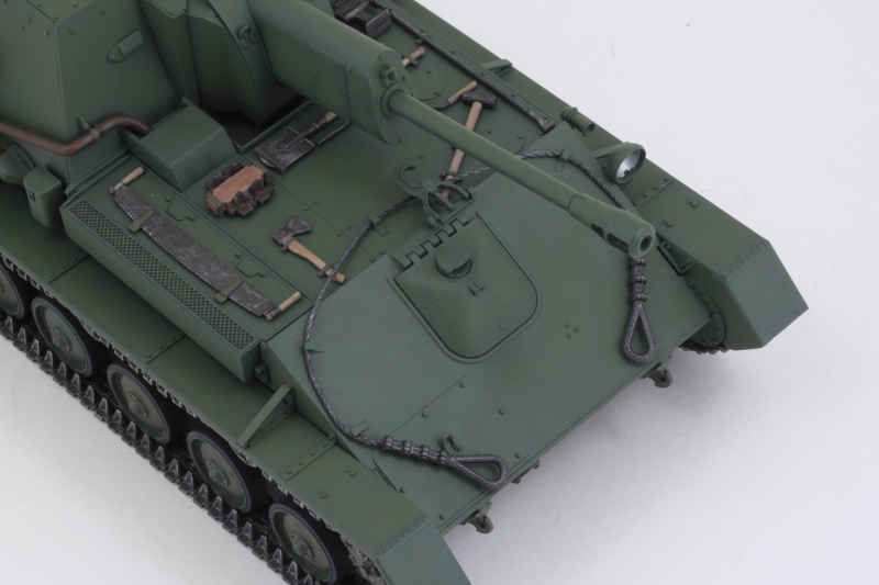
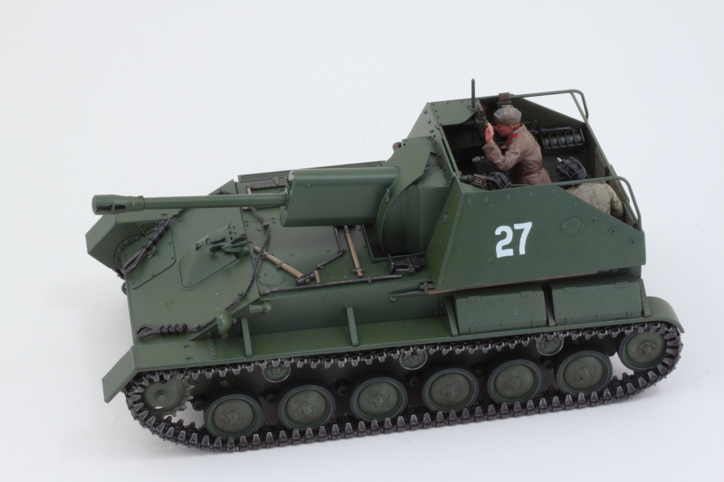
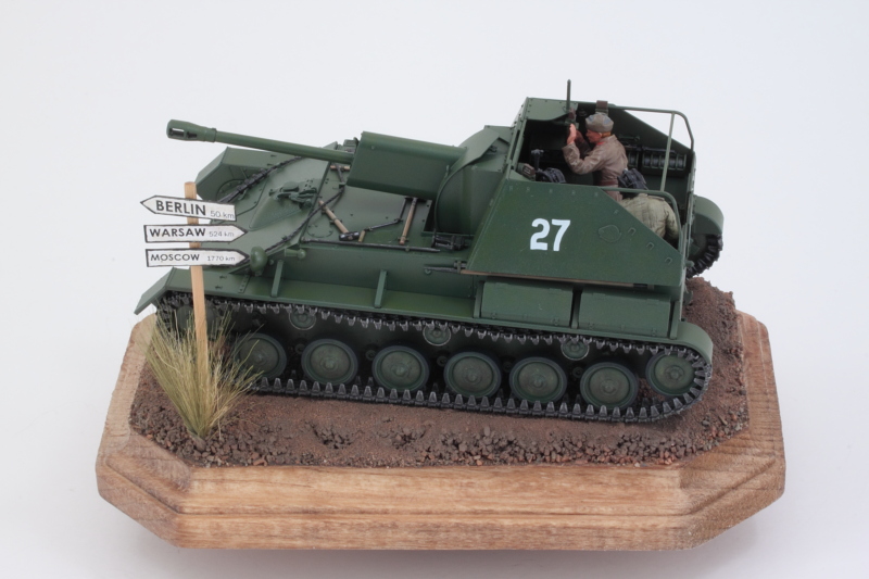
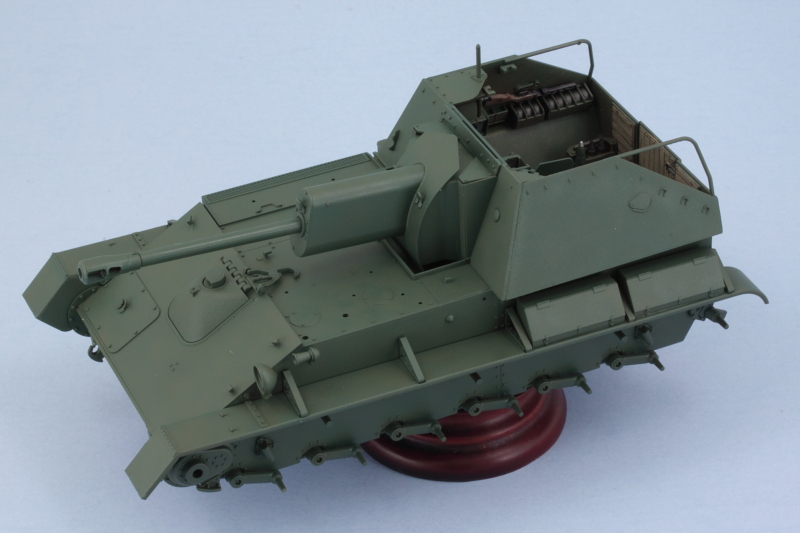
That meant it was time for paint! I airbrushed the gun assembly using the same process on the hull.

Image

Since this was the last time I had planned to have the airbrush set up with the hull colors, I placed the gun and mantlet cover and checked for consistency. After some minor changes and adjustments, it all looks like it belongs to the same vehicle! :)

Image

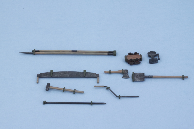
Next up will be dealing with all the hull equipment that needs to go on the main deck and other spots.
Bill Plunk
Posts: 1245
Joined: Wed Sep 28, 2022 10:18 pm

WIP 03-31-2016

Post by Bill Plunk »

I spent the day working mostly on the gun's details so I could get it installed permanently into the compartment. That involved working on several different areas including the gunner's sight. The kit part has solid faces all around, so I used a micro-drill to open up both the eyepiece portion and the top sight opening itself. I also used the same approach as with the fighting compartment to weather the rear parts of the gun and mount to get them to match up.

Image

Detail work also included getting the breech block painted and installed and the bare metal surfaces on the recoil sled picked out.

Image

With the gun now detailed, I installed it permanently into position. I made sure to firmly press the gun all the way down into the polycap's mount since it needs to be down far enough not to cause any interference with the top mantlet piece that locks it all in place. A little bit of liquid glue around the triangle portions of the mantlet piece and some careful gentle finger pressure got it all joined together.

Once I had that done, I also worked on detailing the 3 periscopes that go into the fighting compartment. The kit parts are molded in one piece in the green styrene, not clear, and had an ejector mark on one side that had to be dealt with. To simulate the clear faces, I applied some enamel Steel followed by a dose of Tamiya Clear Smoke. Tamiya does include a clear sprue in the kit (oddly enough, only 1 of the 8 parts on that sprue actually gets used, the headlight lens) but I don't think it's really designed for this kit per se. The clue is that the sprue includes 4 sets of goggles that have no possible use on this vehicle or its figures, so perhaps they just repurposed it from another kit or set? Either way, it wouldn't have been hard to have clear periscopes for a little more detail potential since they are so prominent in the fighting compartment.


Image

I also started on the hull details by working on the side air intake. This is molded solid with a grill pattern so I used a thinned wash of MM enamel Gunmetal to darken up the spaces in the mesh pattern. A careful drybrushing of the 50/50 OD/Russian Armor Green with a small square tip blender brush brought the mesh pattern back out so it would have some depth (or the best possible simulation of it at any rate) to its look.

Image

Tools and the exhausts are next!
Bill Plunk
Posts: 1245
Joined: Wed Sep 28, 2022 10:18 pm

WIP 04-01-2016

Post by Bill Plunk »

The details were the featured item on the menu today with the bulk of the focus on getting the tools detailed and ready for installation. Most of these install on the flat deck in front of the fighting compartment while the gun cleaning rods go under the left side overhang and behind the fender storage boxes. That's why those rods are called out in Step 15 before the fender installation, there's no real easy way to get them in place unless you leave the fenders removable like I've done. The rest of the tools are scattered around in the instructions in Steps 23-25. They were removed from the sprue, cleaned up, and detailed by hand. The only minor annoyance was Tamiya's decision to integrate the two spare links and the jack block into a single piece. It definitely made detailing those two very different elements an exercise in patience!

I used MM Non-Buffing Metalizer Gunmetal as the base for all the metal parts, lightly dry brushed some enamel Steel, then dusted them with some black artist pastels to blend it all together. For the wood areas, I applied a base coat of 50/50 Afrika Grunbraun/Light Gray since it has a nice 'wood' tone, then applied a light wash of enamel Leather followed by some burnt umber artist pastels to get the look I wanted. With all that done, the tools were installed in place.

Image

I did make some minor modifications to the shovel by sanding down its edges to get them more in-scale and also drilled out the exposed end of the gun cleaning rod for a little more detail.

Image

Image

Next up were the exhausts. The two halves were assembled as directed in Step 21 and their join seam sanded down after the glue had set. I applied a base coat of MM non-buffing Metalizer Gunmetal to the bare plastic and then followed that up with multiple applications of a thinned Leather wash to build up some tonal variations. Some burnt orange artist pastels helped here as well and black artist pastels were added to the exhaust tips for some soot accumulation. The exhaust tips themselves were molded solid, so some quick work with a micro drill opened them up. I had to sacrifice one of the t-shaped retaining clamps for the exhausts to the carpet monster, but a quick bit of scratch building using strip styrene and rod gave me an adequate replacement.

I had kept the two different exhaust pipes separate throughout the painting process and only joined them up once I was ready to install them in place. The key is to place the pipes in position first, then feed their long d-shaped tabs into the exhaust cylinders so that everything lines up correctly. Only then did I apply some liquid glue inside the small armored housing on the side of the hull, the connection points to the cylinders, and the small cutout support on the front of the fighting compartment. It sounds complicated but the Tamiya engineering allows you to pull it off with just a little patience.

Image

Always a fun step to get out of the way!
Bill Plunk
Posts: 1245
Joined: Wed Sep 28, 2022 10:18 pm

WIP 04-02-2016

Post by Bill Plunk »

The latest effort was aimed at the lower hull and getting ready for the track installation. First order of business was beating up the lower hull a little bit. I added some wear by stippling and dry brushing a combination of Deep Yellow, Burnt Umber, and some of the OD/Russian Armor Green mix. I also weathered up the sprockets and added some bare metal wear to the drive teeth.

Image

Road wheels also got some wear and attention.

Image

I installed the 6 road wheels per side but left off the idlers for now. I used liquid glue on the arms and cleaned up the long bottom run of the tracks so it could help serve as a guide to ensure all the wheels lined up together while the glue set.

Image

While the road wheels were setting up, I turned my attention to the individual track links. At the start of the instructions they indicate that 6 of the A33 links are 'not for use', so I removed all but 6 links from the sprue and cleaned them up. They have 2 small attachment points that have to be cleaned up but that's not a big deal. I used a small ziplock baggie to hold the links until needed. The links aren't very big and I used the Optivisor during the clean-up as they don't have a large contact surface with each other and I wanted to be sure I kept as much of that intact as possible.

Image

I counted out 34 links as directed in Step 19 and glued them together one at a time into a single straight run using regular glue and tweezers to fit them together. Once the run was together, I used the kit-supplied sag jig to shape the run into the necessary shape. The jig is also plastic, so care is needed in the gluing process so that the run can be safely removed after the glue has set.

The jigs also have an 'F' mark that is supposed to be the front of the run. I noticed after I took the pic that I had the run ends reversed relative to the F, so I swapped it around before the glue had set. I'm not sure that it really matters all that much but better to be safe than sorry! I also double checked the 'hump' in the sag with three of the return rollers on the left side and everything lined up perfectly there too.

Image

I'll let the two sagged top runs set up overnight before addressing the curved runs that connect the top and bottom runs together. All told, the instructions call for a combined 63 individual links to create the tracks runs so that's a total of 126 links between the two sides not including the straight length run already provided.
Bill Plunk
Posts: 1245
Joined: Wed Sep 28, 2022 10:18 pm

WIP 04-03-2016

Post by Bill Plunk »

The moment of destiny arrived today with the rest of the tracks getting assembled and installed. It also reminded me why I prefer workable tracks vs. statics...but since this is an OOB build, I had to stick with the kit-supplied links. They aren't difficult to work with necessarily, they are just tiny, have to be shaped in a specific way, and then need to hold that shape permanently for painting and detailing. That's a tall order and there was more than one occasion where I had to reattach links together at different moments.

First up, the remaining connecting runs were assembled as directed in Step 20. 16 links for the front run around the sprocket, 13 links for the rear around the idler. The fact that the sprocket is able to move in the polycap mount was something that I found made life a little harder...the join spots with the upper and lower runs are in places that the weight and position of the links results in the sprocket wanting to turn...not a good thing. I resorted to small narrow strips of tape to hold it all in place while the glue set.

I also made the mistake of trying to 'multi-task' and assembled the runs for both sides at the same time before I realized just how delicate the whole thing is when trying to line up all the different runs. I was forced into taping and shaping both sides at the same time before the glue set as a result. Now that's a guaranteed exercise in frustration as I quickly discovered, so I'd strongly recommend to anyone else that you work only one side at a time to avoid that.

Image

After the glue had set, the tape came off, and I had the tracks in 4 pieces per side. I made sure to keep the pieces for each side together from here on out as there's no guarantee that one side would fit the other or vice versa. The return rollers were also finished with their bare metal contact surfaces detailed and all 6 were installed. I found in the fitting process that it's just possible to feed the pre-sagged run over the 3rd roller on the right side but definitely necessary to keep the idler separate since I had added the little mudflap extension under the cooling vent.

Image

The tracks were hand painted with a base coat of MM Metalizer Non-Buffing Gunmetal then dry brushed with enamel Steel. The last step was an overall wash of MM enamel Raw Umber. Then the tracks were puzzle-pieced together one more time and glued in place.

Image

Image

Once that's all set, I'll add the fenders to top it all off.
Bill Plunk
Posts: 1245
Joined: Wed Sep 28, 2022 10:18 pm

WIP 04-04-2016

Post by Bill Plunk »

After the tracks had set up, I installed the fenders permanently into place. This went relatively smoothly, I just needed to add a little bit of putty to the left rearmost mount since it attaches right up against the hull side edge. As you can see, there's not a whole lot of clearance tolerance between the fenders and the tracks. Trying to work the indy links with the fenders already in place would probably have been possible since the sprocket can move but it would be a very tight space for sure. I also decided to do a little more tonal work on the hull color, so the masking tape around the fighting compartment was a prep for that.

Image

Image

I have to issue a small disclaimer here for the next little bit as it involves the whole 4BO 'correct shade' debate...which I'm not an expert on and have no interest in trying to litigate. In searching around the 'net, I did find a handy 4BO color chip and this was the 'green' that I've been using as a mental guide in relation to the finish.

Image

Easier said than done, but I've been waiting until I had the fenders on to add the last little touch. I took the 50/50 OD/Russian Armor Green mix mentioned previously and combined it with another 50% MM enamel Medium Field Green. Here's how it looks in the bottle:

Image

I loaded up the airbrush and worked with a very fine detail nozzle (I use an Aztek airbrush, so this is the 'tan' tip) to add this shade over the previous work. I switched to a white background as the blue was playing some tricks and it's hard to capture it effectively, with the white, the photos are closer to what it looks like 'in hand'. Monitor settings of course may cause a variance, but I'm happy with the approximation and subtle changes it introduced to the overall green finish.

Image

Image

While that's all curing (and before I tackle the last remaining hull detail, the tow cable), I decided to give the kit-supplied crew figures a shot. These are covered in Step 37 and are multi-part assemblies depending on the figure in question. They go together easily without the need of much clean-up and are, of course, designed to occupy specific positions/poses in the vehicle with no real room to modify/adapt them. Pictured left to right are the commander, gunner, and loader. The commander's arms had molded solid sleeves on his coat, so I opened them up for a little better detail using a combination of micro drills and needle files.

Image

The commander (aka Comrade Putin) had his hat molded in place along with the head while the other two crew have the padded tanker's helmets as three-piece assemblies that build up around the head. The details on Putin's hat are a little soft as a result when compared to the other two crewmen but each one has their own features/character instead of being cookie-cutter heads. All three have shaped tabs on their bases that are designed to fit their respective torsos, so no swapping around without a lot of work if you wanted to go that route.

Image

I did a test fit with the gang to see how they would all go into the compartment. As I suspected, the gunner is the hardest to position correctly and I found it necessary to remove the C77 gun-control wheel that was installed back in Step 29 in order to be able to move him in and out of position. Once he's painted and positioned, the wheel will go back on so it can match up to his hand to boot.

Image

The loader is going to be holding a round, the instructions want you to fit an HE round but I did a test fit and one of the AP rounds fits just as well, so you can really take your pick since the sprues have 'clean' rounds of both type available for use. As you can see, the crew had to be on good terms with each other, not a lot of room to spread out!
Bill Plunk
Posts: 1245
Joined: Wed Sep 28, 2022 10:18 pm

WIP 04-05-2016

Post by Bill Plunk »

One of the last remaining details for the hull involved the tow cable that the instructions deal with in Step 32. The kit provides a long length of braided string for this and two separate cable loop ends. 100mm of the string is all that's needed and the length of string provided is 500mm long so there's plenty to work with. That's a good thing as the length in my kit had started to unravel on one end, so I cut my length from the opposite end to avoid any problems. Some CA did the trick to combine the string with the plastic ends. 100mm is the perfect length (it includes the amount needed to go inside the cable ends in that requirement) and the string is flexible enough to feed around the storage hooks and over the other kit features. The end that sits on top of the glacis access panel has to sit at a specific angle for it to sit flat, so I started there and looped it around to the other side to see how it would look.

Image

The string doesn't have any 'fuzzing' issues and I tested a short length of the extra (another good reason for the length to be plenty) string with MM Non-Buffing Gunmetal Metalizer to see how it would behave. The metalizer is lacquer-based so I wanted to be sure it wouldn't dissolve the string or do anything else unexpected. It didn't! The metalizer had the added bonus of stiffening the string slightly but not making it unmanageable. I glued the access panel end of the cable in position first since it was the key element and after it set, glued the opposite end to install the cable permanently in place. The movable gun travel lock also showed its value as a feature in this step. While you can't engage the lock to the barrel, the cable needs to pass underneath it and that's done much easier with the lock flipped over on top of the driver's hatch then flipped back once the cable is in place.

Image

With that taken care of, I returned my attention to the crew figures. The heads were hand detailed and brought to life, the irony being that only one of the crewmen (the loader) is positioned so that their face is fully visible, but I couldn't have them feeling neglected despite that fact. For the tanker helmets, I applied a base of Flat Black and then dry-brushed a medium gray over that to bring out the excellent details in the kit parts. For Comrade Putin's 'ushanka', I discovered in doing a little research that these were typically a combination of brown and gray wool and not fur, so I did my best there to replicate that with some custom paint mixes.

Image

The uniforms were hand detailed as well, again with some custom mixes and use of internet research images as a guide to get a close approximation to shoot for. I decided to give the loader an HE round to hold and painted it up to match the other rounds in the ammo bins. A quick dose of Lusterless Flat had the break-dance trio ready to take their places.

Image


Image

I have to say that I'm really impressed with the level of detail that Tamiya provided in the figures...even to the point of detail that would be invisible once the figures were in place. The best example of this was providing pants detail for the commander underneath his great coat. It would'be been all too easy to just leave that as a blob of plastic. They also provided excellent facial detail on the crew and I was a little saddened by the fact that the one with the most expression, the gunner, becomes totally invisible once he's in place in the fighting compartment. He's got an intense look as he peers through that sight!

I placed the gunner first as it took some fiddling to get the elevation wheel to fit his hand and have him stand properly in place. Worth the effort though to have that little detail included. The commander was added 2nd and then the loader positioned in his comfy spot to round things out. Last but not least, I added the crossbar for the fighting compartment as directed in Step 37. It took a bit of finger pressure to coax the two sides of the compartment to meet up properly with the bar. Once it was set, I painted it to match the rest of the hull.

Image

The whole vehicle is now assembled. Next up will be sealing it up and adding the decals.
Bill Plunk
Posts: 1245
Joined: Wed Sep 28, 2022 10:18 pm

WIP 04-07-2016

Post by Bill Plunk »

The kit includes two markings options and I decided to go with the 'Unit Unknown, Karlshorst district, Berlin, 1945' as I also decided to put the vehicle on a small base (more on that in just a second) and a Berlin vehicle was going to fit nicely with that plan. The markings are simple, just vehicle numbers on the sides and rear. I also liked the '27' option since the rear number is different from the sides, gives it a little more character vs. the uniform '30' option that was the other choice for that unit.

Usual drill with an airbrushed coat of Future, decals applied, dosed with Solvaset for them to snug down, then a 2nd coat of Future to seal them in and protect from the weathering process.

Image

Image

While all that was in the 'hurry up and wait' phase, I also worked on a simple base over the last couple of days. I had a shaped wood base laying around that was just the right size, so it was stained and given some basic ground work...only about 10% of the base will actually be visible once the vehicle is placed, so no need to get super fancy. My idea is the 'road to victory', so it's a road pointing towards Berlin in April 1945. The vehicle will get weathered to match up to it in the steps to come. I used some Woodland Scenics 'field grass' and scratch built the road sign. The post is a sanded down bamboo skewer that I stained with real wood stain and the signs were done in Photoshop, printed out on paper, and then taped to a sheet of styrene. I cut out the arrows using the printed templates and then glued the paper to the styrene with Gator Grip thin blend glue. A bit of detail painting and some careful dry-brushing added the black borders and a little wear and tear. Google helped with the Km distances so that all three signs would be accurate on the assumption that you were 50 km from Berlin at that particular spot.

Image

Image

Getting much closer to the finish line on this little guy, now the fun begins!
Post Reply