Dragon Imperial Series Pzkpfw III Ausf. M/N Sdkfz 141/2 (2009)

Bill Plunk
Posts: 1245
Joined: Wed Sep 28, 2022 10:18 pm

Dragon Imperial Series Pzkpfw III Ausf. M/N Sdkfz 141/2 (2009)

Post by Bill Plunk »

This is a project that I've been gathering up items for over time slowly and the last one arrived yesterday by UPS, so it's ready to go. I will be building it as #421 with the 15 PzRg, 11 PzDiv at Kursk. I will be using photos from the Bundesarchiv photos and additional photos from Achtung Panzer #2 as a basis for some of the "individual" characteristics that this vehicle has.

Image

Image

Image

Image

The build will also include the following items:

Dragon Imperial Series Kit #9015 Pzkpfw III M/N Sdkfz 141/2 as the base kit...
Image

...and the following AM items to help dress it up a little:

Aber #35A27 Pz III/StuG III top fenders (to replace the damage that will happen with removal of some molded on items not applicable to this variant)
Aber #G05 PE intake grilles
CMK spaced armor PE bits/Model Point brass barrel and locking ring/turned brass coaxial MG34 from Armorscale barrel set
Eduard #35697 Pz III M/N Detail Set
Eduard #357006 Pz III M/N Schurzen
Model Kasten SK-18 40cm tracks (kit supplied links are incorrect for Kursk since they are later style solid horn with ice cleats)
Model Kasten white metal Bosch light to replace kit part with sink mark in face
Model Point turned brass MG-34 barrels tank variant (kit provided barrels are inaccurate)
Voyager turned brass and PE smoke grenade launchers (including grenades)
Tank Workshop resin tall Pz III hull width rear storage box
Tank Workshop resin Pz III wheels without hubs (1 pair)

Image
Bill Plunk
Posts: 1245
Joined: Wed Sep 28, 2022 10:18 pm

Re: Dragon Imperial Series Pzkpfw III Ausf. M/N Sdkfz 141/2 (2009)

Post by Bill Plunk »

I received in my copy of Pz Tracts 3-3 today and was elated by the timing...but it turned out to be a cruel twist as well. I trust the PT scale plans because they take the full scale drawings in CAD and then scale them down to 1/35 when they publish instead of just copying other drawings and, given the Jentz/Doyle penchant for precision, would take them over another source in the event of a conflict/contradiction. Sadly, it reveals that the scale drawings in the Achtung Panzer #2 that I was relying on for my choice of barrels in terms of accuracy are in fact wrong. It's ironic because now none of the barrels that I have actually match up...but the one that I was prepared to say was the most accurate (the CMK) is now actually the 2nd least accurate (7mm too long) with the worst accurate being the JR barrel (9mm too long but taper now in the right place!) while the Armorscale (2mm too long) and Model Point (2mm too long) barrels are the closest matches. Looks like I might be going with the Armorscale after all. The Armorscale barrel arrived with a damaged mantlet but I can repair that (no big deal as it will be hidden by the spaced armor) with CA gel in order to make the most out of the situation but now will not have a scale-accurate barrel regardless of which one I use. While an irritation, it's just something that I will have to soldier on with I guess!
Bill Plunk
Posts: 1245
Joined: Wed Sep 28, 2022 10:18 pm

Re: Dragon Imperial Series Pzkpfw III Ausf. M/N Sdkfz 141/2 (2009)

Post by Bill Plunk »

I did some spot checking with the various kit parts today and after sleeping on this for a night and looking back at the reference photos, I realized another little detail that's pushing me towards my final choice...the pre-formed brass locking ring on the Armorscale barrel has little screw slots on the exterior commonly seen on the III-Js. The vehicle I'm modeling has the later style smooth locking ring, something that the Model Point barrel replicates perfectly...since the Model Point barrel is the same length as the Armorscale, it wins out on this particular detail. So things have come full circle since that's the barrel I originally had planned for this and bought back in 2005! In a supreme case of irony...the two-part barrel that the kit supplies matches perfectly to the PT 3-3 scale plans but is a two-part barrel with the inevitable seam top and bottom...so definitely a case of pick your poison.

All is not lost however, I will be using the Model Point barrel and the kit supplied mantlet (which means some cleanup is going to be necessary) but stealing the very nice turned brass coaxial MG 34 from the Armorscale mantlet and combining that with the CMK PE pieces (which I noticed on inspection were done by Eduard!) for the spaced armor. A little bit from each one to get the best of all possible worlds. Now I can get down to actually starting to get some steps done. Stay tuned for an update later today. ;)
Bill Plunk
Posts: 1245
Joined: Wed Sep 28, 2022 10:18 pm

WIP 05-09-2009

Post by Bill Plunk »

This is not the first Imperial Series Pz III/StuG III kit that I've built so I was already familiar with the likelihood that there were going to be unneeded locator marks, detail that needed to be removed, etc. This kit followed the usual trend, so the first order of business was to remove the molded on lines for the lower hull that weren't going to be used. This was accomplished using a combination of a micro chisel and a sanding twig.

Image

Next up was Step 1 in the instructions which deals with the sprockets, idlers, return rollers, and road wheels. The road wheels didn't need much in the way of clean-up, just their two sprue attachment points per wheel half since there isn't a mold seam on the rubber portion. I removed all 14 wheel halves (12 main and 2 spare) and they will be assembled later on after painting. I also cleaned up the 2 wheel halves for the extra wheel that will get mounted on the left fender for #421 from the TWS set. Since they were resin, they needed a little more work to open up some of the holes. Some just had a slight film to remove on the larger holes while the smaller ones needed some work with a pin vise to open them up properly.

The drive sprockets and idlers were assembled from their two halves. The sprockets went together easily with just a small amount of flash to remove on some of the drive teeth. The idlers required substantially more cleanup as each half had four sprue attachment points on the outer rim and a node with two points between each spoke, so careful work with de-spruing tweezers and a sharp #11 blade was needed to get them in shape. The return rollers were also cleaned up and assembled without any issues.

Knowing that this build was coming up, I'd already started working on the replacement tracks in my spare time during the weekday evenings and have assembled 2 runs of 90 links each. These were test fit on the sprockets and idlers and everything works well together in that department.

Image

Step 2 calls for the installation of the remaining suspension elements. Since the suspension arms are already molded in position, this is a quicker task than might ordinarily be expected. The final drive housings were installed along with the front and rear shock absorbers and the bump stops for the first and last swing arms. The bump stops require their lower mounting pin to be shaved off since there's only one hole in the hull however this hull is far too large to be of much use and is a guide only to get you in the neighborhood. I also installed the idler mounts, unfortunately these are in a fixed position so it doesn't provide any flexibility in that department, so the exact number of links I'll need per track side will have to be determined later.

Image

Step 3 deals with the installation of the running gear, this was skipped for now as is my normal practice. Step 4 calls for the joining of the upper and lower hull halves but before going that far I knew from previewing the instructions that a lot of work was needed on the upper hull first and it would be easier to do that before it was joined to the lower hull. The first item of business was the removal of the molded on mount points for the Notek light and width indicator lights that weren't present on the M that I'm building (although some did have it according to Jentz in PT 3-3 but that's another story!) and the instructions call for their removal. Removing them creates prominent scars in the molded on tread-plate pattern on the fenders, so my solution was to fit the Aber brass fender top sections to restore the lost detail.

To do that, the first thing needed is to shave down the tread-plate pattern that remains on the front fender sections. This was done using a half-moon micro chisel and then sanding down the sections to provide a level gluing surface to take the Aber brass replacements.

Image

I also took advantage of the opportunity to remove the mold lines for the turret splash guard, front hull lifting eyes, access hatch hinges, splash guard for the driver's visor, and rear lifting eyes behind the turret since none of these were needed. Some of these are called out in the instructions for removal while others are not, so a careful check of the references and line drawings in PT 3-3 were very helpful in that regard.

The Aber fender tops cover the entire fender but I only needed the front section, so I used a pair of sprue cutters to cut off the front section and then used a pair of side metal cutters to reduce it down to the right length for the patch I'd cleared on both sides. The Aber pieces had a slight curve to them for some reason, so both were annealed using my kitchen gas burner flame and then glued into position with CA gel.

Image

With that taken care of, I could now proceed with joining the upper and lower hulls. The fit is generally good except at the front where a small gap will require some putty attention but I was going to redo the weld seam in that spot anyway so it won't create any real additional work. I used regular Testors black bottle glue to provide a good grip and then added rubber bands and a follow up dose of Testors liquid glue to insure a solid join all around. The rubber bands were removed after 2 hours to avoid too much long term strain on the fenders but the hull itself will be left overnight to thoroughly set up before proceeding.

Image
Bill Plunk
Posts: 1245
Joined: Wed Sep 28, 2022 10:18 pm

WIP 05-10-2009

Post by Bill Plunk »

Made quite a bit of progress today...after calling my Mother and wishing her a Happy Mother's Day first of course! Continuing on from yesterday's efforts, I completed the remaining items from Step 4 by installing the rear hull armor plate and the upper hull overhang. The overhang had three square raised molded on sections that needed to be removed, easily accomplished with a #11 blade and some sanding. The crank starter port cover was also added but to get it to fit at the proper angle, a rivet needed to be removed and the hole in the plate slightly enlarged as well. Some putty work was also needed on both sides to close up gaps with the rear hull

Image

Moving on to Step 5, this deals with the special deep-wading exhaust system and air intake seals found on the M. The exhaust is a complex assembly consisting of 5 parts for the exhaust itself plus another 3 parts for the exhaust pipes. I assembled the exhaust first and used liquid glue on all the join seams to get a tight bond then sanded them down with a sanding twig for a seamless all-around look. I also opened up the 6 rectangular ports in the top portion of the exhaust by first drilling them out with a pin vise and drill bit and then using a square tipped needle file to restore their rectangular shape. The muffler and pipes were then installed into the hull. The exhaust air flaps for the engine compartment were also assembled and installed in the open position since mine's not going to be engaged in any fording activity in the near future.

Image

Step 6 adds some detail to the lower hull underside as well as the rear towing pintles and the add-on towing hitch for a fuel trailer. The mount for the towing pintles fit well to the hull but the join with the idler mount required some putty and sanding on both sides to get the right seamless look.

Image

Step 7 returns to the hull front and I addressed the gap on the nose and glacis with a good dose of Squadron White putty. After it had dried, I used the back edge of a #11 blade to score it for the weld pattern. The brake vent housings were added and I installed the MK white metal Bosch light and mount on the left fender and added the wiring conduit by drilling a small hole in the mount housing and gluing in a short length of 0.5mm diameter solder with CA gel. #421 has a peculiar characteristic in that it's missing the Bosch light and mount on the right fender and instead has it replaced with what looks like a field-expedient replacement using an older automotive-style headlamp found on the earlier Pz III Ausf. The kit had one on Spue H, so it was easily adapted by cutting of the angled foot mount and gluing it in place along with a solder conduit. The headlight face had a slight sink mark so some putty work was called for to fix it. In the reference photos it's pretty clear that this is a non-standard fix as the light isn't centered and is shorter than the left-hand light...but it worked I guess for the crew needs! The light post was glued to the fender using CA gel to secure it in place.

Image

Step 7 also called for the installation of the fenders but I wanted to install the superstructure front plate first to avoid possible damage, so the plate was added along with the ball mount for the MG34 and the driver's visor in Step 8 first. I replaced the kit MG34 with the turned brass Model Point barrel and this required the opening in the ball mount to be drilled out and enlarged to take the barrel, easily done with a larger bore drill bit and some trial and error. Once the barrel fit, I fed it through to the proper depth and then secured it in place with some CA gel. Quite a bit of the barrel stuck out in the rear, so once the glue was dry I cut that done with side cutters so it would fit into the recess available in the kit plate. The kit plate was then installed using a combination of regular and liquid glue to get a good join. A small amount of putty was required on both the sides but otherwise it fit well.

The Eduard PE front fenders were used in place of the kit parts and the right hand fender was annealed after it had been bent to shape over a gas flame to allow it to receive some damage. The reference photos show that the right hand fender was banged up some while the left hand fender was in near perfect condition...so maybe whatever banged up the fender also took out the Bosch light on that side? Who knows...in keeping with the photos, I used a combination of flat nosed and needle nosed pliers as well as the handle of my hobby knife to mimic the damage as close as possible before installation.

Image

Step 9 calls for the installation of the front hull spaced armor or Vorpanzer plate. The shot of #421 from Achtung Panzer shows that the top sheet metal covers are missing from this area along with the sheet metal cover on the right side while the left side is still in place. I couldn't replicate this with the kit-supplied parts since it has the top covers integrated into the supports for the plate that join to the superstructure roof. Fortunately the Eduard set included PE braces/supports with the covers separate so this gave me the flexibility I needed.

I bent the PE part to shape first and then glued it into the kit plate with CA gel. Once set, multiple test fits were needed to get the top and bottom arms of the support frame in the proper position but once that was settled, I installed the splash guard for the driver's visor and then installed the Vorpanzer plate and frame. The frame was carefully glued down to the superstructure top using CA gel and careful pressure one point at a time until it had firmly set.

Image

Rounding things out for the day, I added the side hull lifting eyes called for in Step 8 but not accomplished until now to avoid possible damage during handling of the front hull. The reference photos show that #421 had grab handles added to the brake access hatches but I'm going to hold off adding those until I have a chance to play around with the spare track runs since how high the handles are will impact how the tracks sit on the glacis and hull front.

Image
Bill Plunk
Posts: 1245
Joined: Wed Sep 28, 2022 10:18 pm

WIP 05-17-2009

Post by Bill Plunk »

Got quite a bit done this weekend in terms of overall progress especially in regards to the details. The first order of business was to finalize the details on the front hull in relation to the spare track arrangement found on #421. There are two non-standard crew modifications that needed to be added. The first was a rod welded between the brake vents that held a spare track run. I cut some 1mm diameter rod down to size and glued it into place with some CA gel. The standard spare track holder for the hull nose was added courtesy of the Eduard PE detail set. The kit doesn't provide any parts for this, so I was glad the Eduard set had one otherwise I would've had to scratch build one myself.

The second was the addition of grab handles to the transmission access hatches. The presence of these grab bars is what explains the unusual angle of the spare tracks propped up against the spaced armor, so these were added using the same 1mm diameter brass rod cut and bent to form handles 6mm wide and 2mm tall. I drilled shallow holes into the hatches to give them something to blue into and the first attempt for the hatch in front of the driver's visor ended up being a little off center...so those holes were filled with putty and new ones drilled to correct.

Image

#421 has an interesting mix of solid horn and open horn spare tracks so to recreate this I used some of the kit-supplied indy links for the solid horn runs. These had their ice cleats shaved off on the track faces so they would sit properly in the nose rack and on the glacis. 14 links were used for the nose and 8 for the glacis. Before gluing together, I used a pin vise and a micro drill bit to open up the empty track pin holes on the front and rear links of each run. For the open guide horn spare tracks, I used 8 links in two runs of 4 and tested them against the grab handle to make sure I had the angles right. All of the track runs were left removable to make it easier to paint and detail them later on.

Image

Moving on to Step 10, I decided to replace all of the tow cable holders with the Eduard items. The Eduard items provided the correct parts to create the revised tow cable layout found on the Ausf L and later models, so I used their diagrams along with the scale plans in Panzer Tracts 3-3 to get the placement correct. The sunken molded locator points were first filled in with putty and sanded down and then the Eduard items in their respective places. The tow cables will get added later so the final clamps were added to some spare tow cable ends from the spares bin and test fit just to be sure it would all work in the end.

Image

The rest of Step 10 calls for the addition of the hinges for all the engine deck hatches as well as the armored vent covers. These were added without incident. The rear fenders were also installed in this step and the Eduard fenders unfortunately weren't usable as the right side fender had the incorrect open hole for the brake light that wasn't installed on the Ms, so I had to use the kit fenders instead. The right side fender had its cut-out filled with putty and sanded down and a small rectangular piece from the Aber tread plate cut to size and glued over the bald spot where the brake light would've mounted.

Image

Step 11 is a big step in that it adds all the details to the left side fender. I had originally planed to use the Aber intake screens but once I saw how little is actually visible even with the seals in the raised position, I decided to save them for another project and instead used the Eduard provided screens. These fit like a glove and then the raised seals installed over the intakes. All of the pioneer tools had their molded on clamps carefully removed and the Eduard PE clamps installed in the various positions.

I also used the Eduard supports for the antenna tray which needed a little spacer on the front foot in order for it to sit properly and have all three feet contact the fender. The PT 3-3 volume unfortunately doesn't have any diagrams of the schurzen-equipped M in it so I was very nearly led astray into mounting the antenna tray in a level position...however if this is done the rearmost schurzen support arm can't be installed properly so the kit and Eduard set have it right, just some fine-tuning is needed to get the support feet to sit properly. I also installed the aerial swing arm in the upright position after removing the post and drilling out a hole with a #75 drill-bit to accept an Armorscale 2m brass antenna later on. Even though the aerial tray isn't installed until Step 14, I went ahead and did that here since the next step was going to install the schurzen rails.

Image

Staying with the work on the right fender side, I did skip Steps 12 and 13 since those deal with the left fender. Step 14 deals with the installation of the support arms and rail for the side schurzen plates and this proved to be much more of a challenge than I had anticipated. I originally planned to replace these wholesale using the Eduard provided items and dutifully constructed the supports and had progressed pretty far, getting the mounts secured to the hull and installing the rail successfully using CA gel to join the PE mounts to the hull. I then test fit the PE plates and discovered that the mounts were not strong enough to support the plates and the handling required to get them on and off and the CA kept giving way. After fighting with it for a couple of hours and even trying to solder the PE supports to the rail to provide some added strength...I came to the conclusion that the Eduard designed supports just weren't up to the task required of them, so I swapped them out with the kit styrene mounts instead. These were glued directly to the hull with regular glue and allowed to dry and then the PE support rail added using CA gel.

Image

A test fit using the Eduard PE plates revealed that the cut-outs on the middle two plates weren't wide enough to fit the gaps available so I carefully cut down the little mount rectangles on the top of the rail with sprue cutters to create the necessary clearance. The plates then fit well and will get squared up when the lower supports get added. Those won't be added until after the schurzen plates and the fender/hull have been painted to make it easier to get to all the nooks and crannies.

Image

Next up will be the same treatment for the other fender!
Bill Plunk
Posts: 1245
Joined: Wed Sep 28, 2022 10:18 pm

WIP 05-22-2009

Post by Bill Plunk »

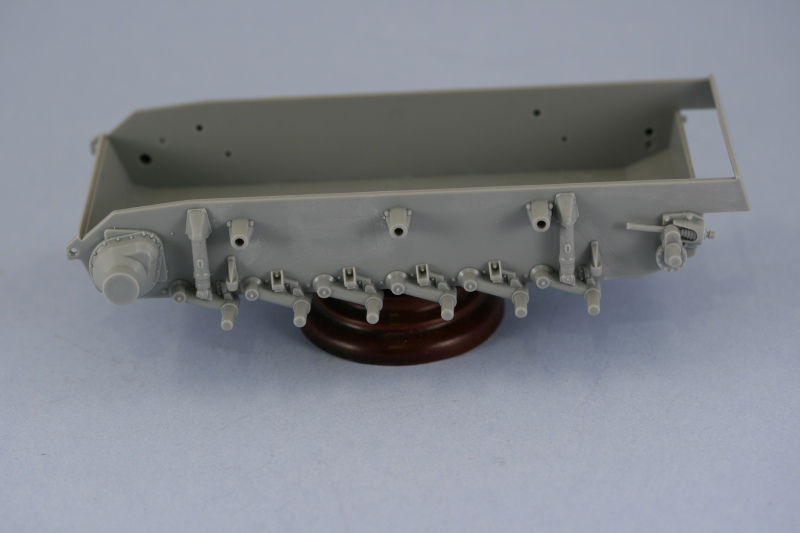
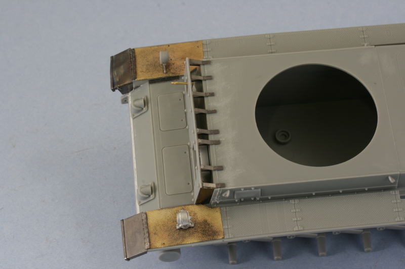
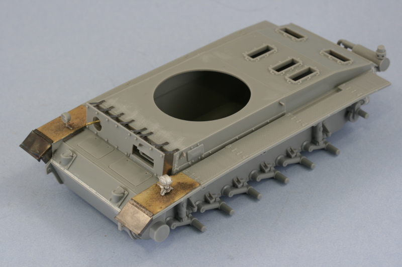
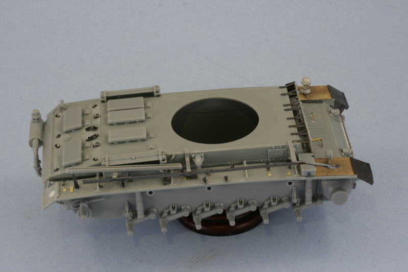
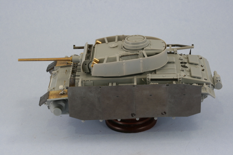
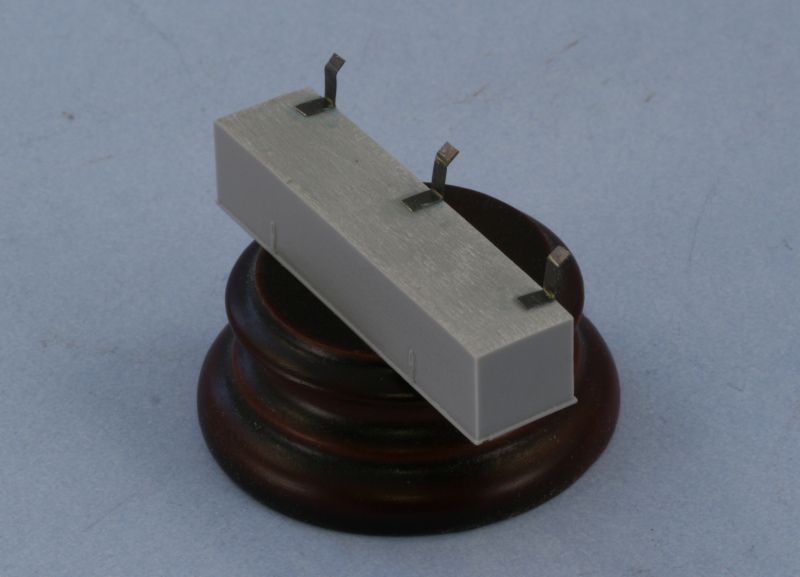
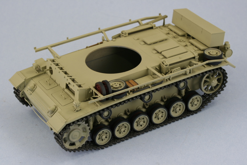
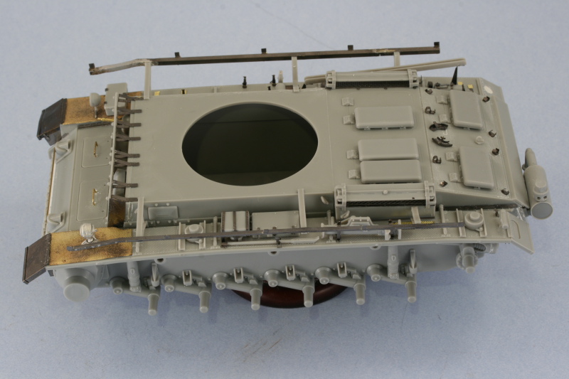
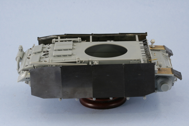
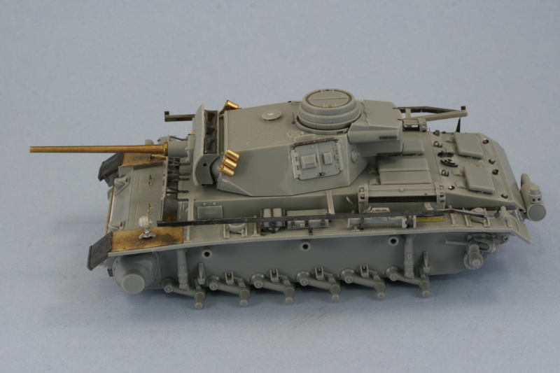
I was able to get in quite a bit of time today since I'd taken the day off for the Memorial Day weekend and the first order of business was to return to Step 12 and 13 and deal with the details on the left hand fender. At first I thought this side would go easier since there are fewer items to deal with but in the end it turned out to be just as much work as the other side. After much deliberation, I decided that the most important thing to install first were the schurzen rail supports in order to insure that they lined up correctly with both sides. To achieve this, I used a ruler and placed a marker dot with the tip of a black Sharpie in order to have a good location guide and then installed all three supports for the left side.

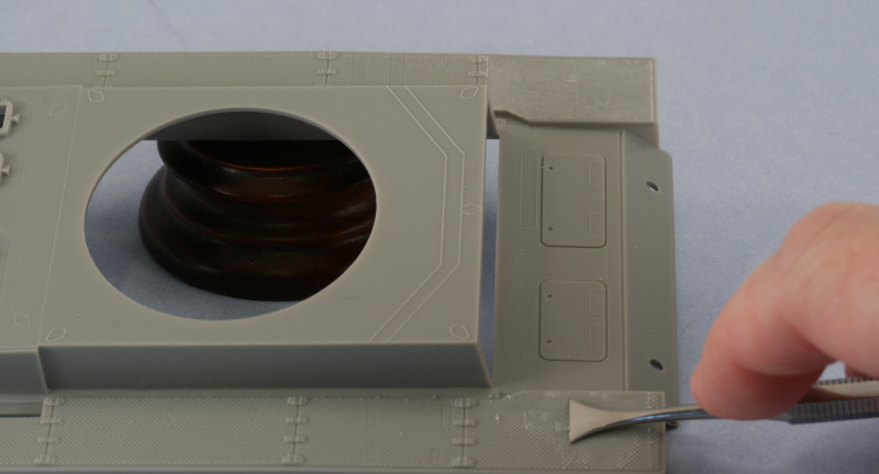
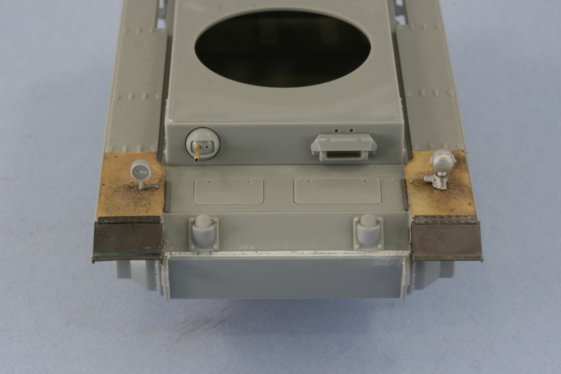
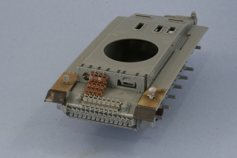
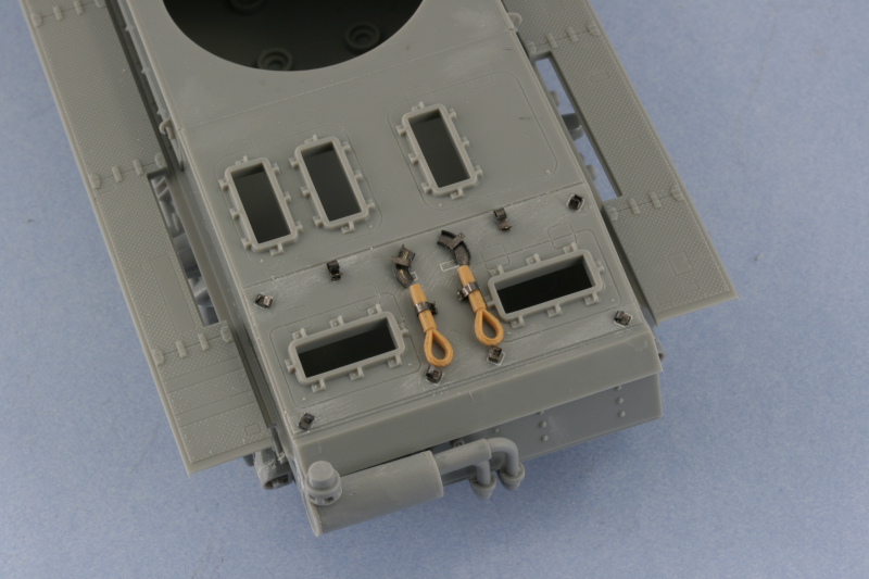
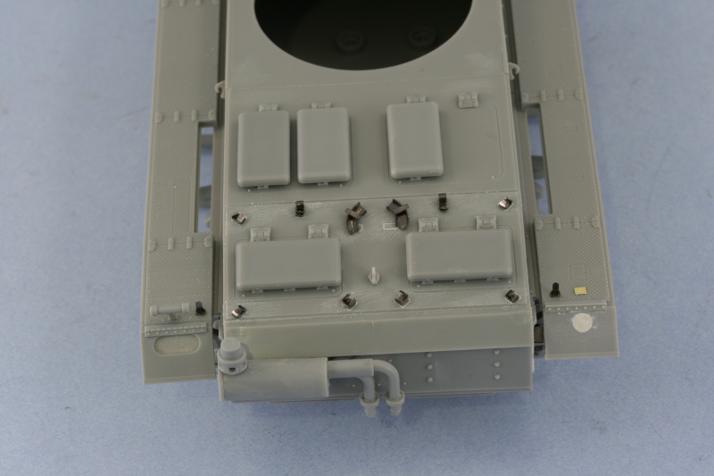
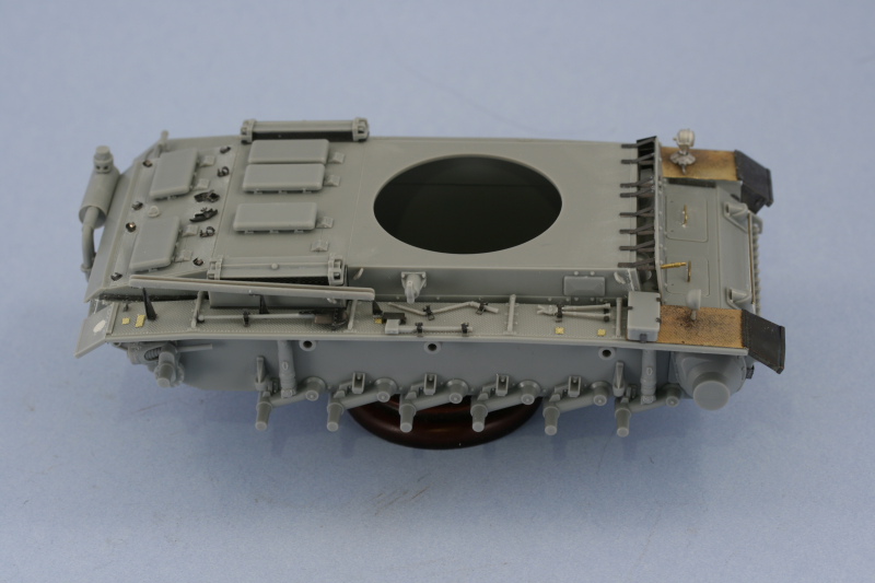
With those as my fence posts so to speak, it was now time to install the other various details and arrange them so they would all play nice with each other. First were the spare wheel holders and the front wheel holder needed to be moved about 1mm further toward the rear vs. the locator marks provided on the fender would suggest. This was necessary in order to allow sufficient clearance for the loose 3rd spare wheel that needs to be wedged between the wheel rack and the schurzen support according to the reference photos on #421. Next came the jack, I replaced it's molded on mounts with the Eduard items and secured it into place. The molded on bald strip where the fire extinguisher would normally go was filled in using another handy strip of the Aber fenders cut to size and glued in place with CA gel. Moving in on the middle portion, I removed all the molded on detail from the jack block and rebuilt it using the 7 PE parts provided in the Eduard set. I could only fit 1 S-hook underneath it instead of the 2 due to space limitations, so a small sacrifice was made in that department. The tool box received new patches and was glued in place and then the clamp and holder for the long pry bar were last. The pry bar wouldn't actually fit in the space available without interfering with the jack, so it was carefully trimmed down at the pointy end and then reshaped to allow it to fit in the triangular holder.

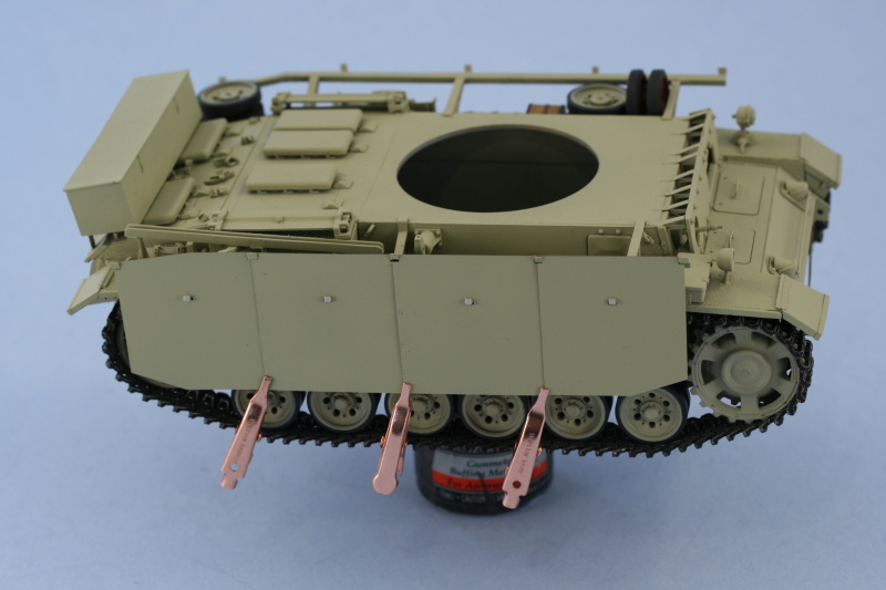
With all that set, I then installed the left side schurzen rail and let it all set up.

Image

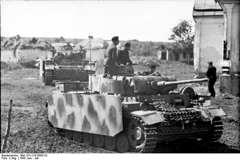
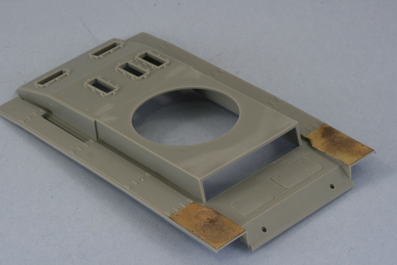
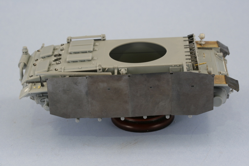
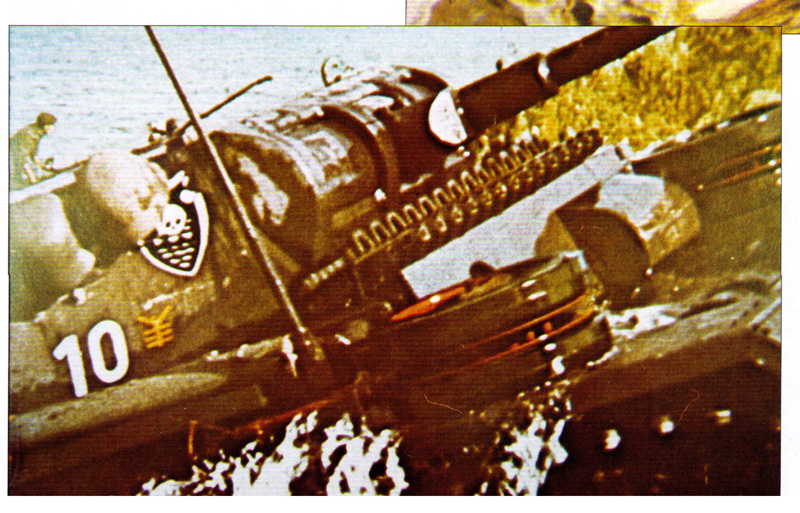
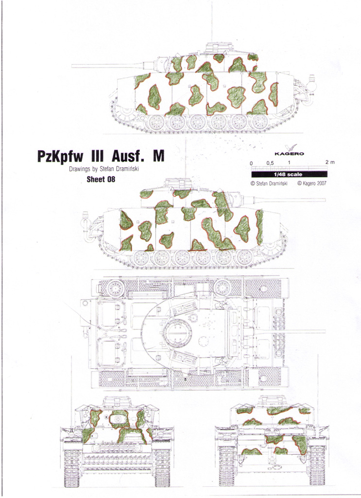
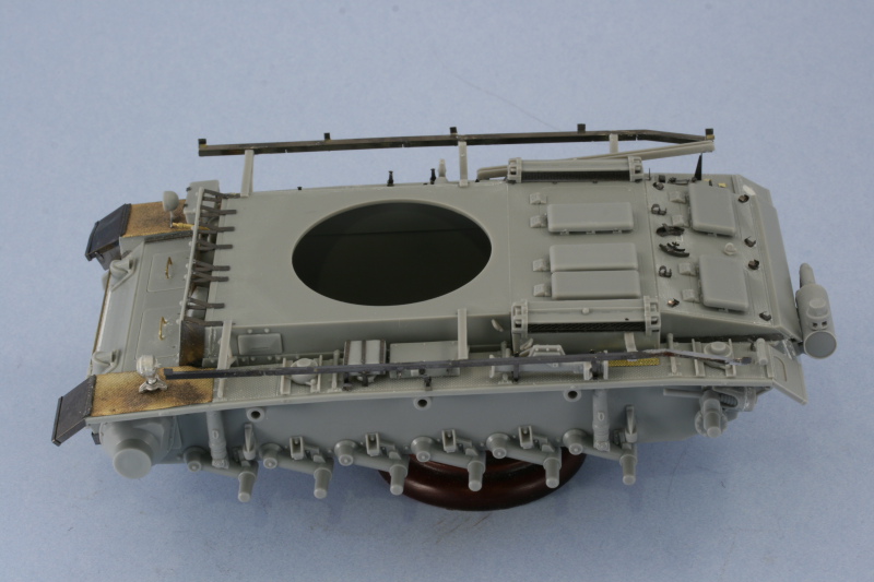
After having done all that and gotten ready to work on the turret as the next phase, I started looking at the reference photos again in order to determine what details I needed to adjust and how I was going to go about them. It was then that I realized something that I hadn't before...#421 has the side schurzen for the hull mounted in reverse from what the DML and Eduard instructions called for. The angled bend in the rails is mounted at the rear and not the front as called for and which I dutifully followed in the PE and kit instructions. This sparked my curiosity so I went back and looked at multiple III-Ms with schurzen to see if DML and Eduard had gotten this wrong somehow. What I found is that the schurzen were often mounted either way...which makes sense I guess when you realize that these were field-installed kits and not factory installed so some variation would be possible and the photo references bear this out.

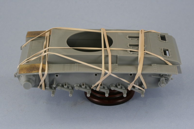
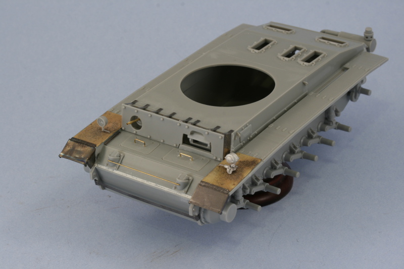
While that gave me some peace of mind that I was in fact not going crazy or seeing things...it did mean that I needed to remove the rails from both sides and swap them around to get the right arrangement as that featured on #421. This was accomplished by carefully removing the rails from the support arms and then re-gluing them to the correct side. Getting them to realign properly was a lot trickier doing it this way since I'd lost my frame of reference originally used on the first installation, so once one side was in place the other had to be carefully lined up with it using visual points of reference on the vehicle itself.

Image

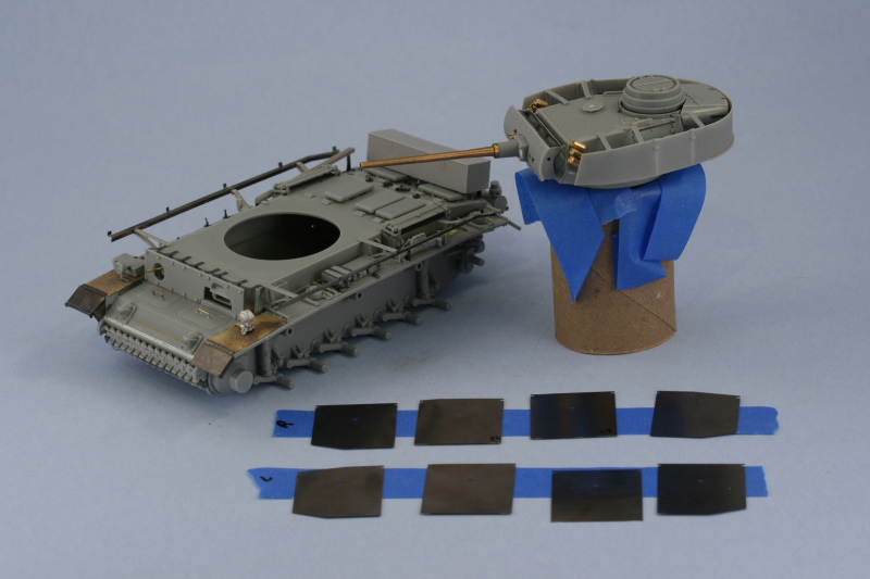
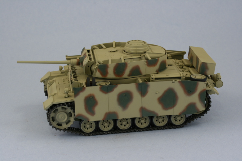
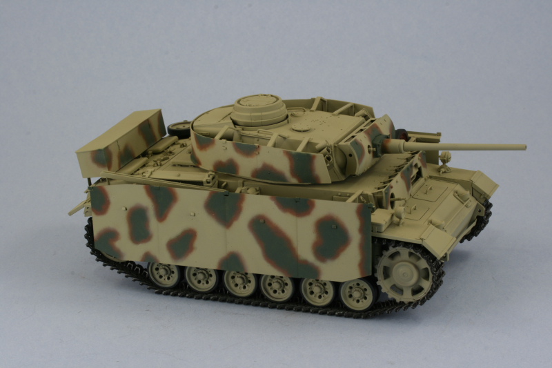
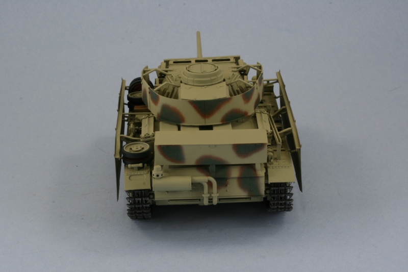
The schurzen were then test fitted on both sides to make sure I had the right height alignment as well as horizontal alignment. Everything looked good so it was on to the turret after a couple of hours of reworking some of the previous stuff.

Image

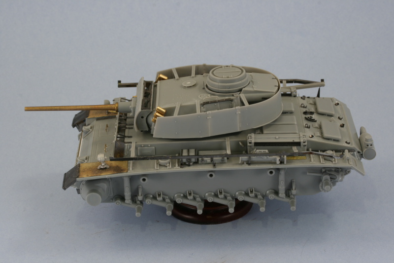
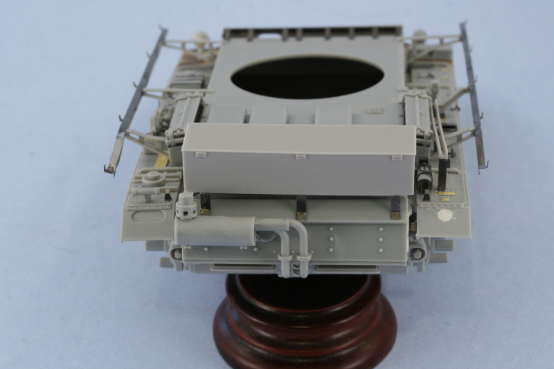
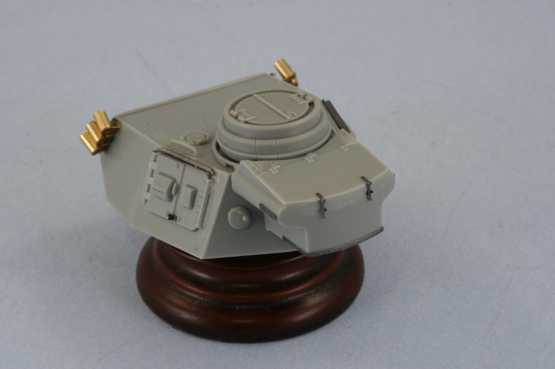
Work on the turret begins in Step 16 and this calls for the joining of the upper turret half with the lower and the installation of the internal portion of the mantlet and gun mount. The two turret halves generally fit together ok but there was some slight damage to the triangular cheek pieces that required some careful gluing and putty work to correct. The two-piece gun mount was assembled and the seam carefully sanded down since it's partially visible even with the external mantlet fitted and the pivot mounts installed allowing the mantlet to still elevate freely. The pivot mounts needed some putty work to fill a slight gap on both sides.

Image

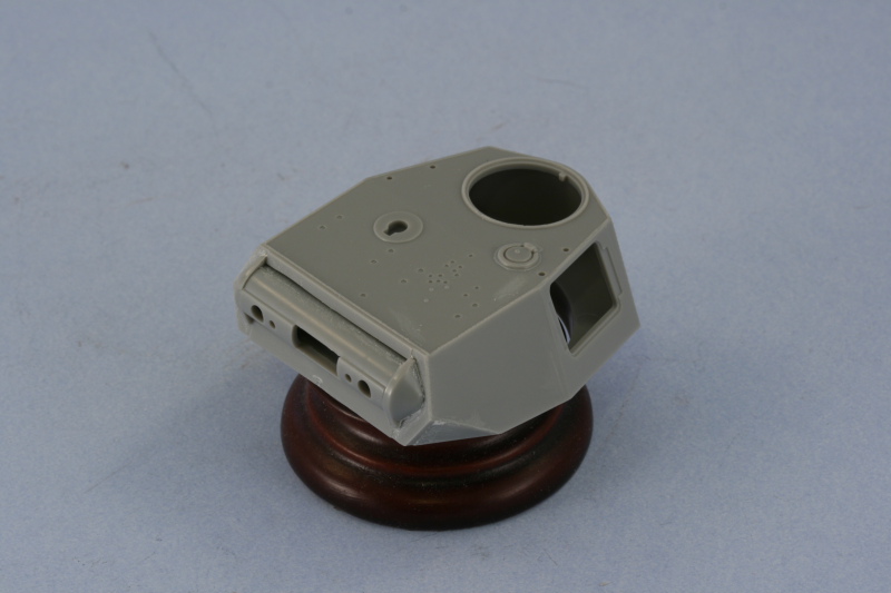
Step 17 assembles and installs the commander's cupola. This went together without any issues and installed the hatches in the closed position. The splash guard ring had it's molded on sight pointer removed and the Eduard PE item installed in its place. The armored ventilator cover had a mold sink mark in the center that was filled with putty and carefully sanded down before it was glued into position.

Image

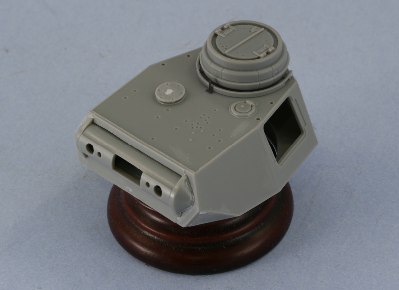
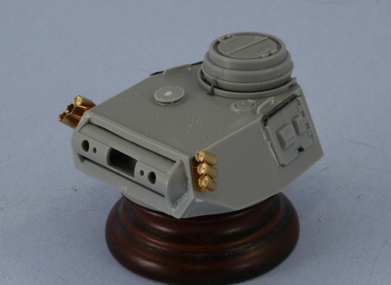
Step 18 adds more details to the turret in the form of the smoke launchers, side hatches, grab handles, and the rain gutters. I replaced the kit parts completely with the Voyager PE and turned brass set and left the lower two launchers empty on the right hand side in keeping with what shows in the photos. The Voyager PE parts for the lifting hook were insanely tiny to work with so I used the Eduard PE lifting hooks instead.

The one-piece side hatch doors were glued into place and their locking points removed and replaced with the Eduard items. Some putty was required to close up slight gaps on either side of each hatch set and the rain gutters were completely replaced with the Eduard PE items. The kit-supplied grab handles were added to the turret roof but the holes provided are too large of a diameter, so once the handles had set more putty was used to fill the remaining holes to round out this step.

Image

Step 19 adds the rear turret bin and the pistol ports to the turret. The bin is two-piece and went together fairly easily with just a little bit of putty required at one corner. The molded on latch tabs were removed with a #11 blade and the Eduard items added in their place and the absent wood rubbing strips added to the bottom and sides also courtesy of the Eduard set. The bin was then carefully installed to the turret rear taking care to make sure it was lined up square since that will be important when the turret schurzen are fitted.

Image

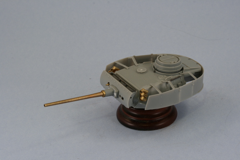
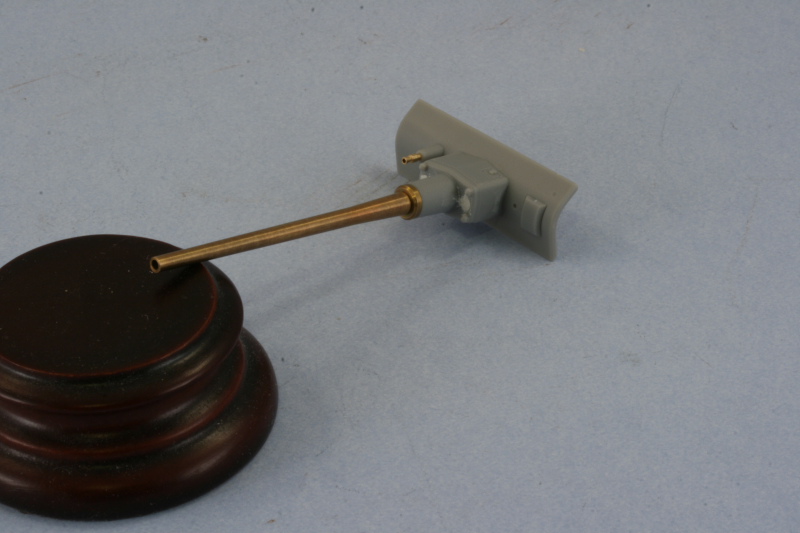
Step 20 deals with the construction of the external mantlet and main gun and installation into the turret. I assembled the two-part recoil housing and once the glue had set carefully sanded down its seam and then glued it into position on the mantlet. The gunner's armored port was added as well and the coaxial MG installed using the turned brass barrel from the Armorscale damaged set mentioned in my first few posts. The kit barrel was replaced in its entirety using the Model Point turned brass barrel and locking ring which were installed using CA gel to insure a solid tight join. The end of the barrel recoil housing had two very prominent ejector marks which had to be filled with putty and carefully sanded down in order to eliminate them.

Image

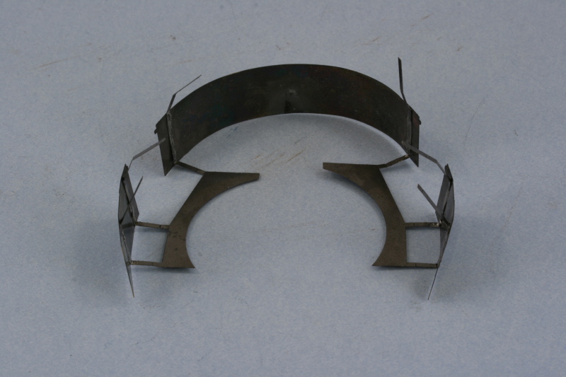
Next came the moment of truth...the construction and attachment of the Vorpanzer plates and spacers and then installation into the turret. To accomplish this, I opted for a hybrid approach using the PE from the CMK set for the top and bottom braces while staying with the kit-supplied styrene parts for the curved side plates for better strength and adhesion to the styrene external mantlet. Once the Vorpanzer was assembled and set, the mantlet was then glued into the turret. Since the inner portion of the mount could still elevate, the weight of the barrel pulled it all the way down.

Image

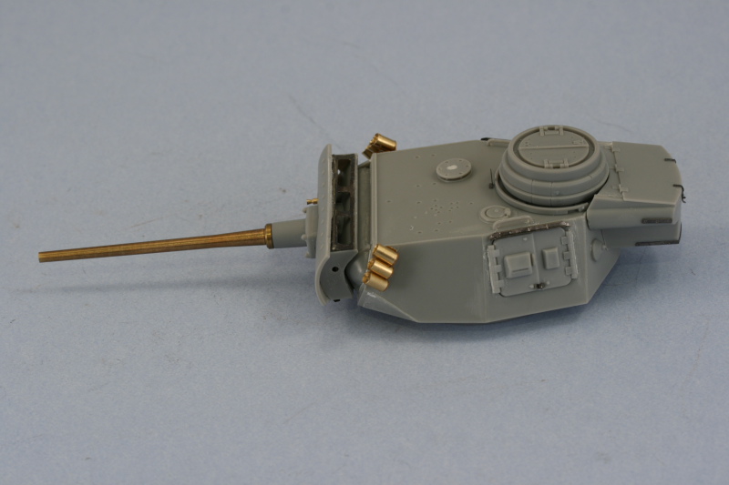
To deal with that, I carefully applied some liquid glue on the inside of the mounts and then positioned the gun barrel in the desired elevation. It was then allowed to set up for an hour while in position on the hull to be sure it was where I wanted it to be.

Image

The last thing to deal with before paint is the turret schurzen, so that will be goal #1 for tomorrow!
Bill Plunk
Posts: 1245
Joined: Wed Sep 28, 2022 10:18 pm

WIP 05-23-2009

Post by Bill Plunk »

Today's efforts were all about the final element of construction, the addition of the turret schurzen. I had to give this a lot of thought because of the way the Eduard set is laid out. It has a kind of unique approach in that the 3 support arms are already attached to a base plate that is designed to go under the turret and thereby insure that all the arms are already in the correct positions. This just leaves the separate plates which then need to be attached to the support arms. The first order of business was to remove all the necessary parts and remove attachment burrs where appropriate with the Dremel.

Image

As you can see, the rear plate is flat and needs to be curved to fit around the turret rear and sides. The front plates also need a slight curve introduced to them as well. To accomplish this, each plate was annealed over a gas burner with locking tweezers and then, using the kit styrene parts as a mold, formed into the necessary curved plates.

Image

Now came the fun part...figuring out how to best attach the plates to the support arms and then get the whole arrangement onto the turret. Because of the tension of the curved rear plate and the weight involved in general for the whole assembly, I knew that soldering was going to be the only real way I could get the strength and durability needed. So I broke out my trusty 0.5mm solder and Tix Flux and the soldering iron and set to work.

Image

The first order of business was to get the support arms bent with the proper 90 degree angles needed to join up with the schurzen plates. Once those surfaces were defined, they were tinned with solder in preparation for joining to the plates. Tinning is a simple process, some flux was brushed on the surfaces and then the soldering iron used to apply solder to the surface. This makes it easier to get a good solder joint by clamping and heating the parts so that the solder join is on the whole contact surface and not just on the edges.

Image

To achieve that, I first had to lay out the parts and pin them in place using T-pins and a 6"x6" square piece of ceramic fiber board. A couple of smooth-jaw copper clamps were used to secure the surfaces together for joining after the surfaces had some flux applied to them.

Image

Then, using a small square tip on my Weller variable soldering iron set at 5 (40w), heat was applied to the join until the flux boiled away and the solder flowed, creating a solid join.

Image

This process was repeated for the front plates as well until I had all the plates except for the crew hatch doors in place.

Image

The next step involved actually mounting the whole arrangement onto the turret. The two base plate halves were securely glued to the bottom of the turret with CA gel and then I began the process of carefully bending the support arms into position and aligning the plates in the correct arrangement. I had the left hand side all done and started in on the right side when the first disaster struck...I dropped the turret from a height of about 4 feet off the ground and, of course, it landed on the side that was not yet secured. One of the weak points of Eduard PE is that the etched bends don't tolerate a lot of use...they are designed to be bent once and that's it...unfortunately as a result of the drop and the strength of the solder joints, the weak points are exactly at the bends at the top of the schurzen plates and the top portion of the rear right side snapped cleanly through. It wasn't a total loss and was salvageable and I actually got it all back together again with some careful soldering repair but then disaster struck a second time...unbelievably, I dropped the turret again just as I was finishing the join on the repair. Fate was not kind to me today! This time two more bends gave way, one at the base plate and another at the top on two different plates...rendering everything a total loss in the process as the damage was too widespread to be repairable. 4 hours of work out the door in a heartbreaking series of accidents within the space of 10 minutes!

Fortunately, Plan B was available in the form of the kit parts, so these were pressed into service wholesale since even the plates couldn't be salvaged due to the fact that the kit mounts don't align with the metal plates correctly. The front plates had 3 large ejector marks that had to be carefully sanded down but otherwise the assembly and installation went smoothly in less than 1 hour. Such is life as a modeler I guess!

Image

A test fit with the hull showed everything was in order there too, so I decided to also take a shot with the hull schurzen in place.

Image

Image

The last remaining detail is to install the rear hull box mounts and then it will be time for some painting!
Bill Plunk
Posts: 1245
Joined: Wed Sep 28, 2022 10:18 pm

WIP 05-24-2009

Post by Bill Plunk »

After yesterday's experience with the turret schurzen, I was looking forward to a new day today and made quite a bit of progress. First order of business was to decide how to handle the Tank Workshop field-mod storage box for the rear hull. Reference photos of the hull rear for III-Ms with the box fitted are hard to come by but I managed to find one in Trojca's book on the Pz III.

Image

The photo helped answer two questions for me...namely how high the box normally sat in relation to the muffler and how it was mounted to the rear hull. Now that I had that info, I cut off the pour plug with a razor saw and then sanded down the bottom of the box to get it level. I then set about constructing some scratch-built mounts using strips from the Eduard PE frames cut down to form a "z" type brace. I built one brace and then test fit it to the box and hull until I had the right angles, then used it as a master to make 2 more with the same dimensions. Worked out pretty close with only some minor adjustments needed between the three. They were glued in place with CA gel and it was ready to go.

Image

Once I saw how much of the deck was going to be hidden by the box, I decided that I wasn't going to mount a tow cable after all and went ahead and installed the two remaining clamps after removing them from the tow cable ends. Fortunately I hadn't glued them together so it was easy to separate them and do the installation as empty clamps. The box was then mounted with CA gel applied to the front underside where it contacted the armored vent covers as well as to the feet of the braces for the rear hull.

Image

That was the last remaining detail before it was time to paint...so the prep process got underway to make that happen. The first step involved mounting the road wheels, idlers, sprockets, return wheels, and spares on tooth picks with blobs of poster blue-tack putty and sticking them into my trusty empty styrofoam box for easy handling. The draftsman's circle template had the appropriate diameter holes masked off to allow for painting of the hubs by airbrush and they were ready to go.

Image

The turret was also prepped for paint by separating it from the hull and mounting it on a short cardboard tube with multiple strips of painters tape to keep it stable. The tube doubles as a handle when painting but I do have to be careful when moving it around not to let it tip over! The schurzen plates were organized by hull side to keep from mixing them up and stuck onto strips of painters tape as well to make it easy to handle them without risk of dropping or bending in the process.

Image

First step in the painting process was to prime everything using Model Master enamel Italian Dark Brown by airbrush. This serves two purposes...1) it insures I don't have any areas of bare plastic when it comes time to lay down the base coat and 2) is particularly helpful with all the metal parts to insure good paint adhesion and coverage vs. just a single base coat.

Image

While that was drying, I went to work on the road wheels. I can't recall the exact source but I came across a very memorable photo of an assembly line in a factory producing either Pz IIIs or StuG IIIs where the final step involved a worker spray painting the road wheels with Dunkelgelb...but only the exterior surfaces were painted. Thinking logically from that and the famous color photo of the BefPz III coming out of the river,

Image

I decided to paint the inner hubs in Red Oxide primer. This meant that I needed to mix up my own color since there isn't a suitable color in the Model Master range. I used a whole square bottle of regular Testors enamel Flat Red with just a little bit of Flat Black added. A little goes a very long way...and it came out just a bit too dark so I added some additional Light Gray to get it back more to my liking. I mixed up a pretty large batch knowing that it was going to be a hit-or-miss type of effort and so having more paint to work with gave more leeway and had the added bonus that I now have a large quantity of Red Oxide primer ready to go for the future.

Before spraying the hubs, I had primed the entire wheel surface with the Italian Dark Brown as I've had issues in the past with my preferred "rubber" choice of enamel Gunmetal (not the metalizer) rubbing off on the rim edges. I'm hoping that by priming them first with the dark brown, it will help the Gunmetal "stick" better. The rubber was then painted and the circle template put to work. Working from darker to lighter colors, I sprayed the Red Oxide for the inner surfaces first and then let them dry. The outer hubs then received their base coat of Dunkelgelb using a custom mix of 50-50 Light Gray/Panzer Dunkelgelb.

Image

Just as I was cleaning out the airbrush and getting ready to switch to a larger paint cup for the base coat on the hull and turret, it started to thunder and about 5 minutes later the skies unloaded and rained me out of the garage. The rest of the painting will have to wait until tomorrow!
Bill Plunk
Posts: 1245
Joined: Wed Sep 28, 2022 10:18 pm

WIP 05-29-2009

Post by Bill Plunk »

More progress in bits and pieces throughout the week. The first item that needed some attention was the resin empty hub spare wheel that will be mounted between the front spare wheel rack and the schurzen support at the hull front. The TWS resin items are pretty well detailed but lack the small support rods that are the signature detail on Pz III wheels. To add these in, I cut 3.5mm lengths of 0.5mm diameter styrene rod and glued them in place with small amounts of CA gel.

Image

The next round of details needed to address all the hard to get to areas once the schurzen were mounted. All of the fender pioneer tools were detailed off the vehicle with their metallic portions base coated in MM Non-buffing Metalizer Gunmetal and then dry brushed with Steel. The wooden portions/handles were base coated with my own special mix of "wood" color and then given a light wash of Leather to deepen their tone. A light application of Raw Umber artist pastels was also applied using a small Filbert brush. The jack block received multiple applications of the Leather wash, using the brush to create a subtle wood grain pattern in the process.

The road wheels and idlers were mounted to both sides. Everything worked fine in this department except for one road wheel on the left hand side, the third from the rear. It was a "floater" by about 3mm and this presented an unusual problem given that the suspension arms are all molded in place. The solution was to carefully break off the mount point with a pair of needle-nosed pliers and then re-glue it slightly lower so it would align properly and the vehicle sit level.

Image

Image

The tracks also needed to be painted and detailed before their installation. The MK track runs were extended to 92 links per side after a test fit with the now-solid road wheels and were primered with a coat of Flat Black by airbrush followed by a base coat of MM Non-buffing Metalizer Gunmetal also by airbrush. The tracks were then dry brushed with Steel followed by a second dry-brush of Burnt Umber.

Image

The tracks were then installed to both sides. The initial test fit encountered a major issue in terms of clearance space over the rearmost return roller. The fenders there have a rectangular raised outline that corresponds to where the side air intake sits on the top hull. It only extends half way over the return roller but is high enough to prevent the links from clearing. This had to be removed...and it was a tough thing to do at this stage without breaking anything but I managed to get it done on both sides. This would've been much easier if done before the upper and lower hulls were joined, something to remember for future kits as I have the K in the stash and it will likely require the same kind of effort.

Since the schurzen will virtually hide the top run from view in its entirety, there was no reason to include any sag, otherwise 93 links would've been needed. The sprockets and idlers were glued into place after receiving some metal wear on the teeth and contact surface of the idler by first dry brushing Steel and then dry brushing Burnt Umber.

Image

The moment of truth arrived and the schurzen were mounted. I used the kit-supplied styrene mount arms since the Eduard items were too long. The plates were test fit first with the arms and a small bit of blue-tack to mark the spot it would attach to the fender. Paint was then carefully scraped to allow a clean styrene-to-styrene contact surface for solid gluing. Once all 4 plates were in place, the plates were carefully glued at the bottom using CA gel and brass smooth-jawed clamps to insure the plates would all "hang" evenly. This process was applied to both sides.

Image


With that out of the way, I used strips of strategically placed blue painter's tape to mask off the areas around the schurzen on both the lower hull and turret to prevent over spray onto the details. The DML finishing guide wasn't much help or very accurate in recreating #421's scheme, so I scanned in a set of 1/48 plans from Kagero's Photosniper series and then, working from the reference photos, sketched out a close approximation of the pattern using Prismacolor pencils.

Image

With that in hand, I went to work with the airbrush and first sprayed in the green patterns using MM Khaki. Then the border red-brown was added using a 50-50 mix of MM Military Brown and Leather. Over spray was corrected using the original base color and then a light mist coat of the lightened dunkelgelb mix applied to help tie it all together.

Image

Image

Image

Next up will be the rest of the hull details in preparation for moving on to the markings and weathering phases.
Post Reply