Meng German A7V Tank (Krupp) (2018)
-
Bill Plunk
- Posts: 1245
- Joined: Wed Sep 28, 2022 10:18 pm
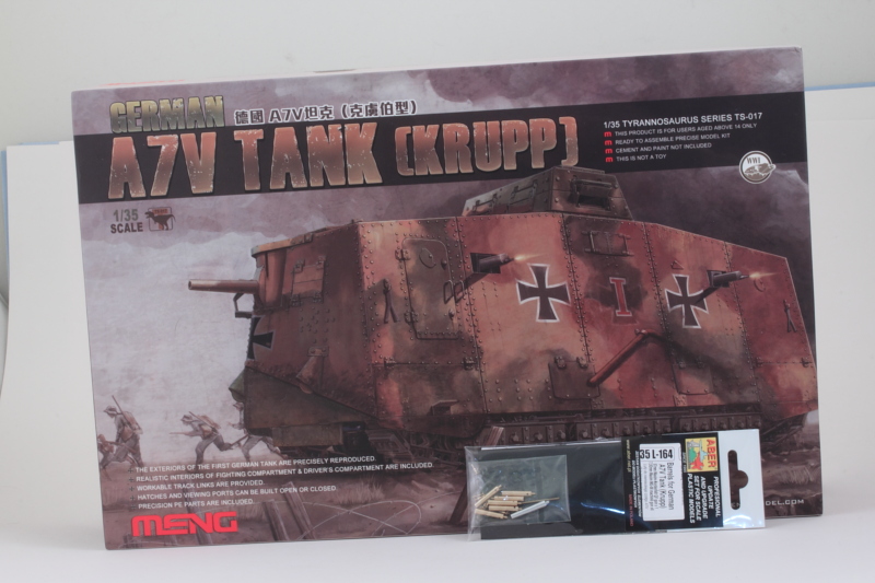
Meng German A7V Tank (Krupp) (2018)
Build log for the 1/35 Meng TS-017 German A7V Tank (Krupp) build project using the Aber 35L-164 replacement gun barrel and MG detail set.
-
Bill Plunk
- Posts: 1245
- Joined: Wed Sep 28, 2022 10:18 pm
WIP 06-12-2018
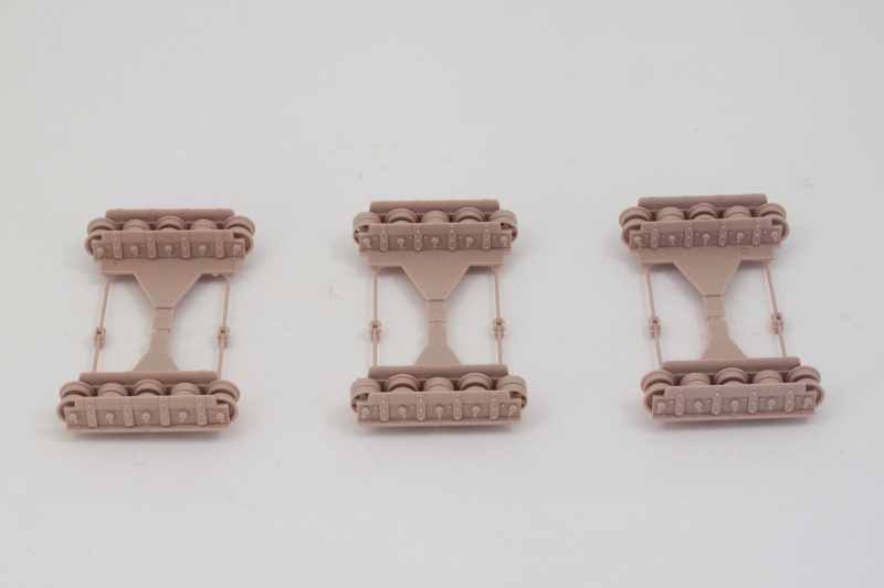
It seems that the German obsession with a ton of road wheels in their armor designs was present from the very beginning! The first 2 steps in the instructions deal with assembling the three roadwheel sets per side that make up the running gear. Each road wheel has two halves to assemble and there are two different wheel types that alternate with each other, so you have to keep those straight in the assembly process. Each set installs to a different suspension module (A17, A16, A15), so I labeled the module with its corresponding part number so I could avoid confusing them. Getting all three modules together with the road wheel assemblies requires no less than 75 parts, so a lot involved to get to this first progress shot! 
-
Bill Plunk
- Posts: 1245
- Joined: Wed Sep 28, 2022 10:18 pm
WIP 06-18-2018
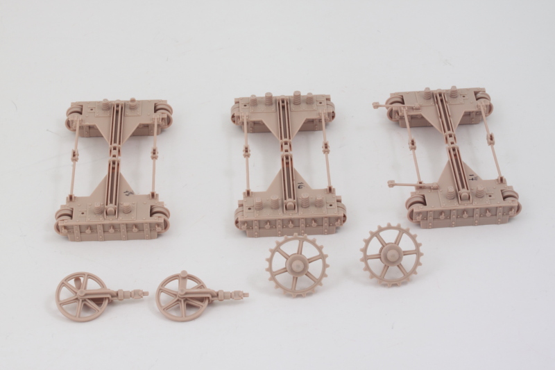
Work continued on the Step 1-2 double-combo related to the running gear with the latest focus on getting the sprockets, idlers, and other details squared away. The idlers assemble in a 'handed' fashion so you have to be careful to assemble them to reflect that. There's no glue involved in assembling them, only snap-fit, so if you make a mistake it's easy to fix. The sprockets don't require the same care as they are identical in their assembly. I added the spring details to the three suspension modules as called for to round things out.
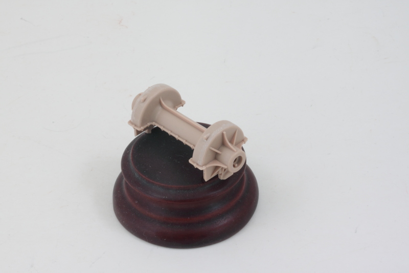
Step 3 assembles the transmission and includes the use of poly-caps trapped inside the side portions to allow the drive sprockets to remain movable later on. Some slight sanding around the join surfaces is all that's needed to create a unified look.
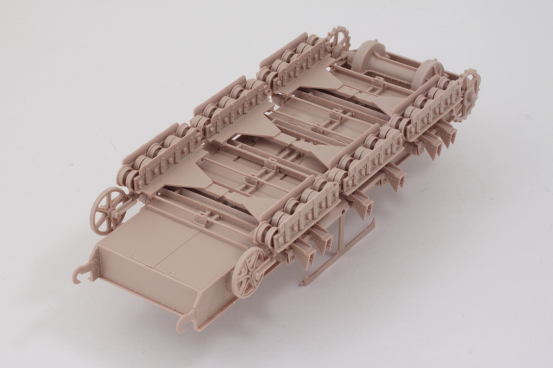
Step 4 is a big step as it assembles the lower hull pan and is a little tricky to get it all together and square. After fiddling with different test fits, I found the best way was to install the nose plate, B3, first since it attaches to the front of the transmission area and provides a solid point to work from. I added the side panel B1 and only applied glue to the support tabs for it to kind of tack it in place. I dry fit the rear plate, B2 in position and then added the other side panel, B18. Only after both side plates were in place did I add liquid glue to the rear plate joins and along the full length of the sides. A couple of sliding clamps helped hold it all together while the glue set up and voila! The lower hull was together.
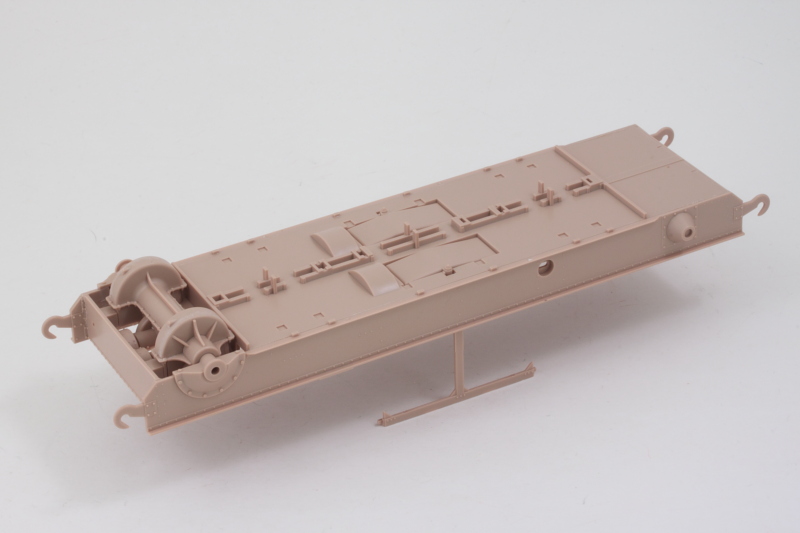
Next up will be adding the support rails and return roller racks which is another multi-part adventure!
Step 3 assembles the transmission and includes the use of poly-caps trapped inside the side portions to allow the drive sprockets to remain movable later on. Some slight sanding around the join surfaces is all that's needed to create a unified look.
Step 4 is a big step as it assembles the lower hull pan and is a little tricky to get it all together and square. After fiddling with different test fits, I found the best way was to install the nose plate, B3, first since it attaches to the front of the transmission area and provides a solid point to work from. I added the side panel B1 and only applied glue to the support tabs for it to kind of tack it in place. I dry fit the rear plate, B2 in position and then added the other side panel, B18. Only after both side plates were in place did I add liquid glue to the rear plate joins and along the full length of the sides. A couple of sliding clamps helped hold it all together while the glue set up and voila! The lower hull was together.
Next up will be adding the support rails and return roller racks which is another multi-part adventure!
-
Bill Plunk
- Posts: 1245
- Joined: Wed Sep 28, 2022 10:18 pm
WIP 06-19-2018
Work continued today on the lower hull and suspension components. The instructions have a separate step, Step 5, that shows the two types of return roller racks that are needed and how to assemble them. They have a very narrow contact surface where the two halves meet up so I elected to install them directly as individual parts to the lower hull as called for in Step 6 versus trying to assemble them as pairs first and then attach them. It seemed to go easier since there are small mount tabs that they need to attach to on the lower hull and the notches in the parts don't always 100% align with them. I used liquid glue and tweezers to work with the halves one set at a time until I had all 6 attached.
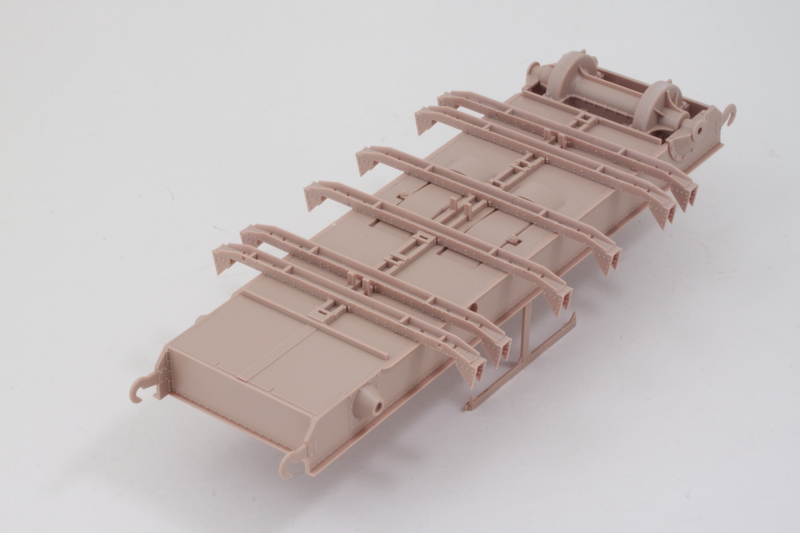
Step 7 deals with the return rollers along with the side mufflers and some bracing for the lower hull. The return roller racks also have two different styles, one for the middle set and another for the front and rear sets. The middle set can be assembled as indicated in the instructions since the bottom edges meet but the other sets have no contact points beyond the friction fit of the two halves inside the return rollers. This means that their only glue points are where the install on the racks, so I had to be very careful in fitting them in place with tweezers and then applying liquid glue once they were set with a small pointed brush to glue them down.
The idlers were installed as well and the sprockets inserted into the poly-cap mounts so that they would stay movable. The mufflers were assembled and carefully sanded to remove their join lines before being added in place on the hull. There was a little bit of play in their mount points, so a little care was necessary to ensure they lined up properly relative to the return rollers to avoid problems with the tracks later on.
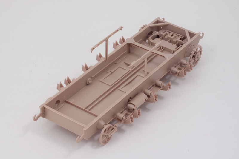
Step 8 is the big moment of truth as it installs the three road wheel assemblies from earlier in place on the hull. I started with the end set with the sprockets and used regular glue on the contact points to ensure it grabbed quickly and held in case small adjustments were needed. You do have to be a little careful in adding the other two modules as they are subtly designed to install only one way to ensure all three line up correctly in the end.
Rounding out the day's efforts, I added the small linkage rods that are called for in Step 9 and the big girl is now up on her feet.
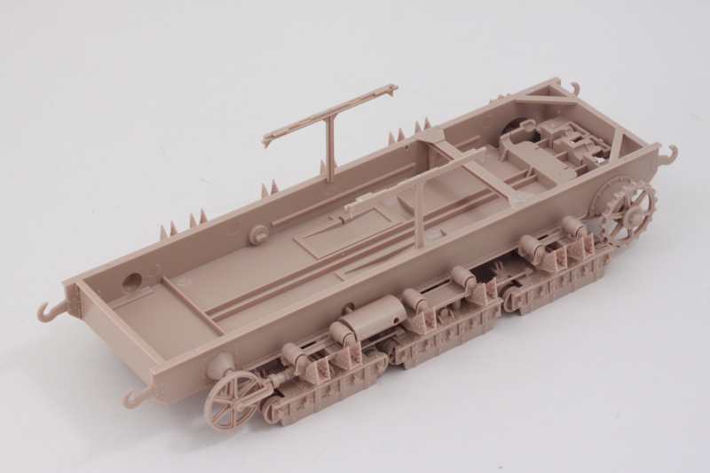
Next up will be tackling the track assembly. There are 48 links called for per side and each one is assembled out of 2 parts, so that will probably eat up a full day or two depending.
Step 7 deals with the return rollers along with the side mufflers and some bracing for the lower hull. The return roller racks also have two different styles, one for the middle set and another for the front and rear sets. The middle set can be assembled as indicated in the instructions since the bottom edges meet but the other sets have no contact points beyond the friction fit of the two halves inside the return rollers. This means that their only glue points are where the install on the racks, so I had to be very careful in fitting them in place with tweezers and then applying liquid glue once they were set with a small pointed brush to glue them down.
The idlers were installed as well and the sprockets inserted into the poly-cap mounts so that they would stay movable. The mufflers were assembled and carefully sanded to remove their join lines before being added in place on the hull. There was a little bit of play in their mount points, so a little care was necessary to ensure they lined up properly relative to the return rollers to avoid problems with the tracks later on.
Step 8 is the big moment of truth as it installs the three road wheel assemblies from earlier in place on the hull. I started with the end set with the sprockets and used regular glue on the contact points to ensure it grabbed quickly and held in case small adjustments were needed. You do have to be a little careful in adding the other two modules as they are subtly designed to install only one way to ensure all three line up correctly in the end.
Rounding out the day's efforts, I added the small linkage rods that are called for in Step 9 and the big girl is now up on her feet.
Next up will be tackling the track assembly. There are 48 links called for per side and each one is assembled out of 2 parts, so that will probably eat up a full day or two depending.
-
Bill Plunk
- Posts: 1245
- Joined: Wed Sep 28, 2022 10:18 pm
WIP 06-21-2018
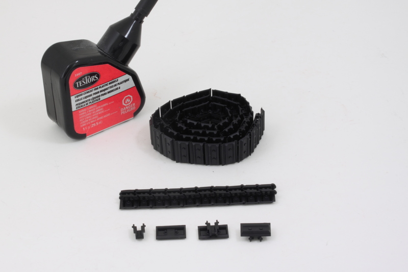
Bench time for the last couple of days has been devoted off-and-on to getting the caterpillar-style tracks assembled. Each link has 2 parts, the bottom portion that contacts the ground and the upper part that contacts the road wheels, sprockets, etc. Meng designed these in a clever way, they only go together solidly one way but you do have to pay attention when assembling them to ensure you don't make a mistake in the repetition necessary to get all 48 links per side together. Fortunately, there are 16 spares available on the sprues if you do make a mistake. I used regular Testors glue to provide a little more grab and control in the link assembly process and worked on 7 links at a time since that's how they are molded on the sprues.
Each part has a pair of contact points and careful removal from the sprues with pointed cutters meant that there was only a little bit of clean-up required before assembling the parts together. Once I had 7 links done, they were clipped together without glue so they could remain workable and then the next links added on in similar fashion until the full track run was created.
I did a check using some small strips of blue painter's tape with each track side to make sure the fit was solid for each run of 48 links. Since neither the idler or sprocket are adjustable, the only flexibility is in the track runs themselves once assembled and 48 links worked beautifully for both sides. The sprockets are fairly stiff due to the poly caps and I ended up turning them with a pair of tweezers to feed the track run through as needed for the test fit.
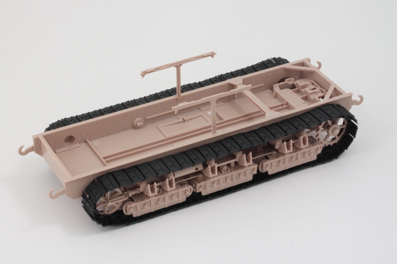
The next step in the instructions calls for the floor plates of the fighting compartment to be installed. These also overhang the tracks, so I will do a test to see how well they can or cannot be fed with the plates in place as that will decide when the first round of paint work needs to be done on the lower hull and tracks.
Each part has a pair of contact points and careful removal from the sprues with pointed cutters meant that there was only a little bit of clean-up required before assembling the parts together. Once I had 7 links done, they were clipped together without glue so they could remain workable and then the next links added on in similar fashion until the full track run was created.
I did a check using some small strips of blue painter's tape with each track side to make sure the fit was solid for each run of 48 links. Since neither the idler or sprocket are adjustable, the only flexibility is in the track runs themselves once assembled and 48 links worked beautifully for both sides. The sprockets are fairly stiff due to the poly caps and I ended up turning them with a pair of tweezers to feed the track run through as needed for the test fit.
The next step in the instructions calls for the floor plates of the fighting compartment to be installed. These also overhang the tracks, so I will do a test to see how well they can or cannot be fed with the plates in place as that will decide when the first round of paint work needs to be done on the lower hull and tracks.
-
Bill Plunk
- Posts: 1245
- Joined: Wed Sep 28, 2022 10:18 pm
WIP 06-24-2018
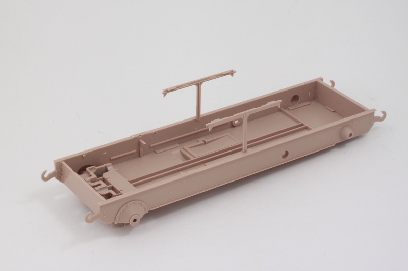
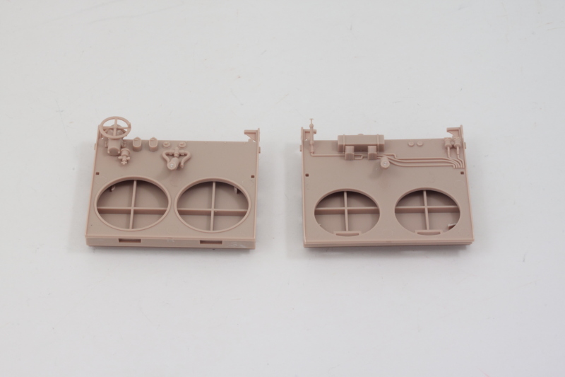
Not a huge update but an important one all the same. I did a test fit with the fighting compartment floor plates and it's possible to still feed the tracks through with them in place without difficulty, so I went ahead with Step 10 and installed the four plates in place. The fit of the four plates together is pretty snug, so it's important to ensure that the front and rear plates are positioned correctly before committing to glue on the smaller side plates. I used some Mr. Hobby Mr. Cement glue for this as it's a little thicker than regular liquid glue and allows more flexibility and applied some of the thinner liquid glue to the seams once everything was solidly in place.
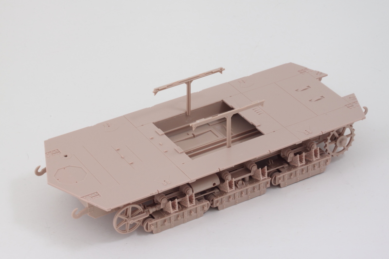
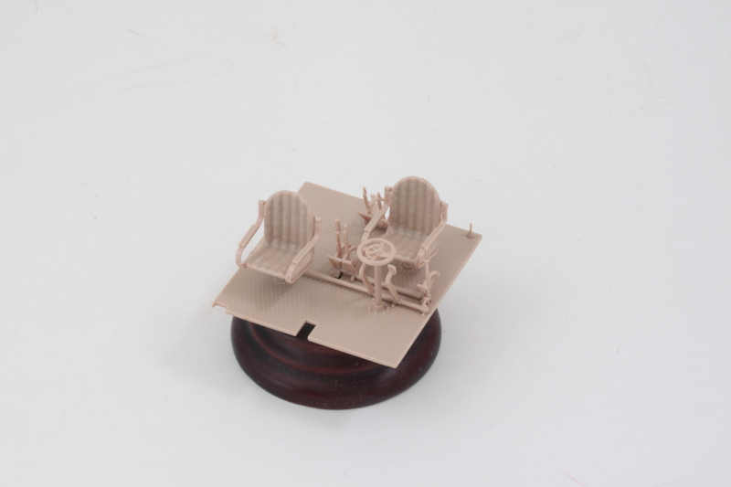
Moving on to Step 11, this assembles the driver's compartment and adds all the details to the floor plate there. It's a little tricky getting all of the control levers together since they are small to begin with and don't have very large contact surfaces with each other where they do touch. I found it easiest to add them into the floor first and then connect them up as needed. For the crew seats, I assembled their sides first and then added the support posts underneath. Once that was solid, the seats were installed on the floor.
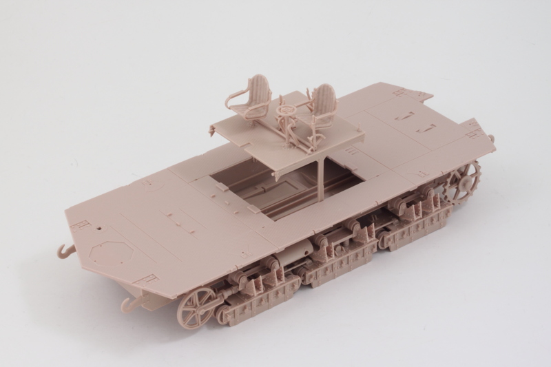
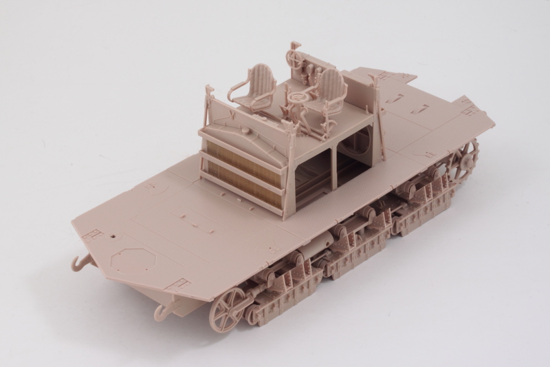
Step 12 is simple enough, it installs the now-complete driver's compartment into position on the support frames over the engine bay. I decided, after much deliberation, not to open up the doors or hatches to display the interior due to the complications involved in painting both inside and outside. That's not to say that it can't be done, I'm just choosing not to do it with this particular build. I'll still build up the interior as called for, especially since many of the components are necessary to support the hull box, but won't be detail-painting them.
Next up are the radiators that install below the driver's compartment.
Moving on to Step 11, this assembles the driver's compartment and adds all the details to the floor plate there. It's a little tricky getting all of the control levers together since they are small to begin with and don't have very large contact surfaces with each other where they do touch. I found it easiest to add them into the floor first and then connect them up as needed. For the crew seats, I assembled their sides first and then added the support posts underneath. Once that was solid, the seats were installed on the floor.
Step 12 is simple enough, it installs the now-complete driver's compartment into position on the support frames over the engine bay. I decided, after much deliberation, not to open up the doors or hatches to display the interior due to the complications involved in painting both inside and outside. That's not to say that it can't be done, I'm just choosing not to do it with this particular build. I'll still build up the interior as called for, especially since many of the components are necessary to support the hull box, but won't be detail-painting them.
Next up are the radiators that install below the driver's compartment.
-
Bill Plunk
- Posts: 1245
- Joined: Wed Sep 28, 2022 10:18 pm
WIP 06-25-2018
Following on with the interior, next up was assembling the front and rear radiator modules. Step 13 details what is needed for them and has them split out as two separate assemblies, so I worked on one at a time to avoid accidentally mixing them up. The forward radiator has a larger step at the bottom to help tell them apart and ensures that you don't accidentally install it in the wrong position since it won't sit at the right height to mate up with the driver's compartment floor otherwise.
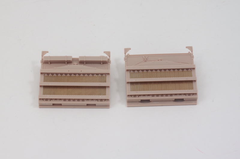
Once both modules were assembled, it was time to add them to the fighting compartment as called out in Step 14. The fit between the two modules, the driver's compartment floor, and the hull floor is pretty tight and it took some gentle pressure and coaxing to get it all to sit together square. Careful use of liquid glue at the connecting points after it was lined up ensured it would stay that way.
Next up is the QF 57mm main gun assembly.
-
Bill Plunk
- Posts: 1245
- Joined: Wed Sep 28, 2022 10:18 pm
WIP 06-28-2018
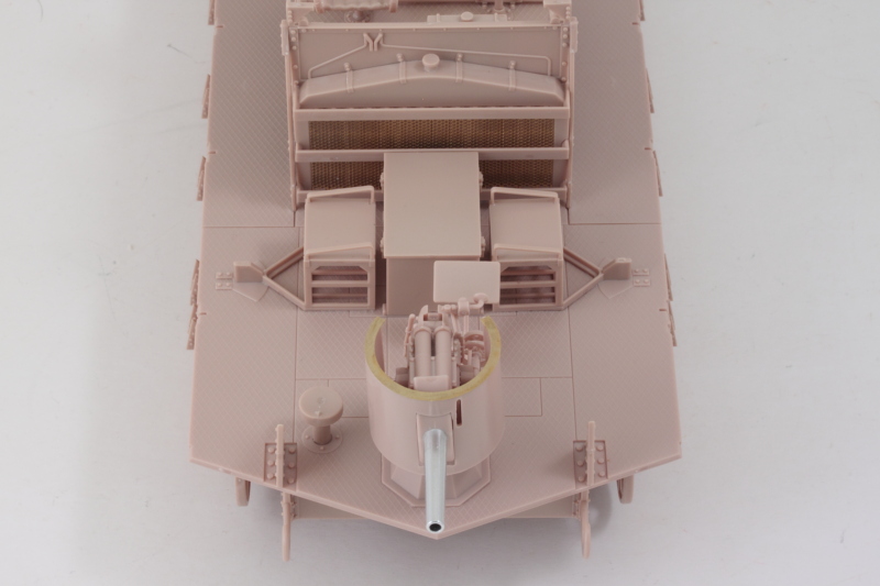
Managed to get the main gun armament done today and completed Step 15. The instructions have this step laid out in sub-steps with arrows guiding you from one to the next and it is important to follow that order to avoid any incidents along the way.
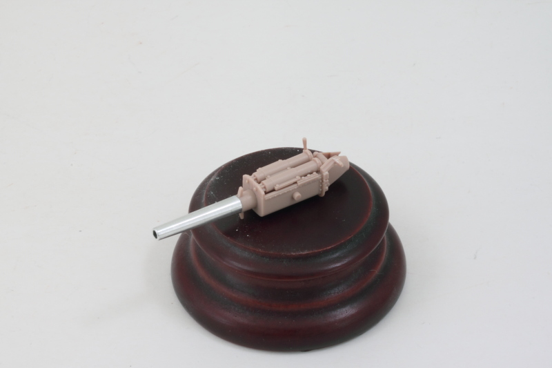
Before I could set out on that path though there was one thing I had to do first. The Aber turned aluminum barrel replacement is designed to install right at the attachment points for the gun shield, so the plastic barrel has to be removed in front of that first. I used a razor saw to remove most of it followed by careful work with a #11 blade to trim it back the rest of the way. Light sanding leveled the face and a drill bit and pin vise opened it up to take the support pin on the aluminum barrel.
I used CA gel to mount the aluminum barrel and then headed down the first 3 parts of the path to get the gun and breech elements assembled. I waited to add the curved shield, part G22, until after it was all set though in case I needed to make any modifications for it to fit correctly.
The next steps on the path add the elevation supports and the gunner's seat along with other details that go with them. Careful work with glue and following the instructions means that the gun can fully elevate but still with enough friction to keep it in position even with the added weight of the metal barrel. The curved shield fit pretty tightly around the barrel replacement, I only needed to do some very slight sanding at the join edge to get it all together cleanly.
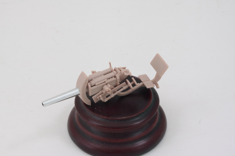
The last few steps on the path add the drum shield for the whole gun and the pedestal mount. This is a little tricky due to the use of a locking c-shaped part that allows the gun to swivel on the mount, but careful work with the glue and tweezers got it to work as designed. It fits a little loosely on top of the pedestal but nothing that should cause a problem.
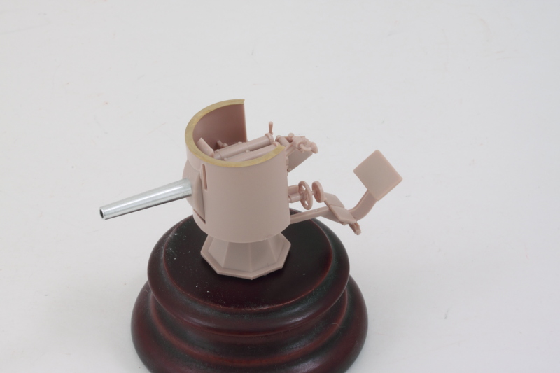
To be sure that everything was playing nice with each other, I did a quick test fit of the pedestal and gun with the fighting compartment floor. The gunner's chair base just clears the floor when the gun rotates, so everything looks good at this point.
Next up will be working on more of the fighting compartment elements.
Before I could set out on that path though there was one thing I had to do first. The Aber turned aluminum barrel replacement is designed to install right at the attachment points for the gun shield, so the plastic barrel has to be removed in front of that first. I used a razor saw to remove most of it followed by careful work with a #11 blade to trim it back the rest of the way. Light sanding leveled the face and a drill bit and pin vise opened it up to take the support pin on the aluminum barrel.
I used CA gel to mount the aluminum barrel and then headed down the first 3 parts of the path to get the gun and breech elements assembled. I waited to add the curved shield, part G22, until after it was all set though in case I needed to make any modifications for it to fit correctly.
The next steps on the path add the elevation supports and the gunner's seat along with other details that go with them. Careful work with glue and following the instructions means that the gun can fully elevate but still with enough friction to keep it in position even with the added weight of the metal barrel. The curved shield fit pretty tightly around the barrel replacement, I only needed to do some very slight sanding at the join edge to get it all together cleanly.
The last few steps on the path add the drum shield for the whole gun and the pedestal mount. This is a little tricky due to the use of a locking c-shaped part that allows the gun to swivel on the mount, but careful work with the glue and tweezers got it to work as designed. It fits a little loosely on top of the pedestal but nothing that should cause a problem.
To be sure that everything was playing nice with each other, I did a quick test fit of the pedestal and gun with the fighting compartment floor. The gunner's chair base just clears the floor when the gun rotates, so everything looks good at this point.
Next up will be working on more of the fighting compartment elements.
-
Bill Plunk
- Posts: 1245
- Joined: Wed Sep 28, 2022 10:18 pm
WIP 06-29-2018
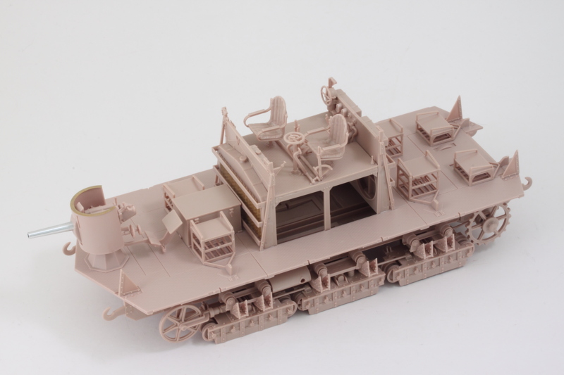
Got the rest of the fighting compartment stuff done today courtesy of Steps 16-18 on the instructions.
First up were the crew seats for all the MG gunners and the large ammo chest for the main gun. The seats are divided into two types, the lower pair that are for the rear-facing MGs and the four that are for all the other side-mounted MGs. The side-mounted seats are taller and are a little trickier to get together. I found the best way was to add the side supports first, then the top seat, and slide in the middle ladder rack last so that it was tight enough to support it. The kit provides optional ammo boxes to go in the racks under the seats but I kept those for the spares box since I'm not showing the interior.
The main gun ammo box builds up around a base that includes detail for the rounds stored inside it but there's no real easy way to show the lid open other than to just leave it off...which may have been the way the real thing worked based on the clasp detail that is present on both sides but no hinges.
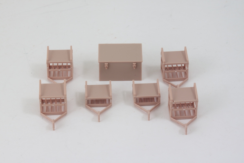
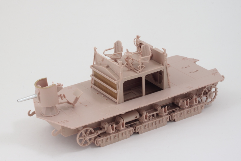
With all the seats built up, step 17 deals with adding them along with other front-end details to the front of the compartment in the form of the angled braces for the nose armor plates and the loader's stool. I used the armored plate (part F2) to help ensure the placement of the braces lined up to avoid problems later on. Ammo box, MG seats, and the 57mm pedestal mount were permanently placed to round things out.
Step 18 does the same thing for the rear compartment and I used the rear plate (part F1) to check its angled braces as well. The rear-facing MG seats have to be carefully placed so that they clear the little half-moon shaped bulges in the floor but still line up straight. I also didn't install the four crew personal weapon rifles as called for, those also will go into the spares bin along with the MG ammo boxes. The sprues that they come on have some additional weapons as well including rifles with full bayonets mounted, so that's a nice bonus.
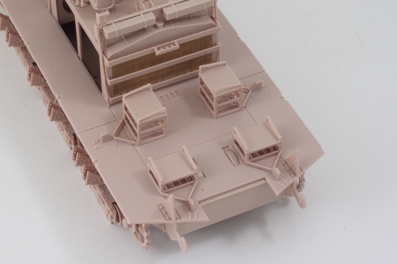
That pretty much covers off the fighting compartment details with the exception of the MGs and their mounts which will be the next effort.
First up were the crew seats for all the MG gunners and the large ammo chest for the main gun. The seats are divided into two types, the lower pair that are for the rear-facing MGs and the four that are for all the other side-mounted MGs. The side-mounted seats are taller and are a little trickier to get together. I found the best way was to add the side supports first, then the top seat, and slide in the middle ladder rack last so that it was tight enough to support it. The kit provides optional ammo boxes to go in the racks under the seats but I kept those for the spares box since I'm not showing the interior.
The main gun ammo box builds up around a base that includes detail for the rounds stored inside it but there's no real easy way to show the lid open other than to just leave it off...which may have been the way the real thing worked based on the clasp detail that is present on both sides but no hinges.
With all the seats built up, step 17 deals with adding them along with other front-end details to the front of the compartment in the form of the angled braces for the nose armor plates and the loader's stool. I used the armored plate (part F2) to help ensure the placement of the braces lined up to avoid problems later on. Ammo box, MG seats, and the 57mm pedestal mount were permanently placed to round things out.
Step 18 does the same thing for the rear compartment and I used the rear plate (part F1) to check its angled braces as well. The rear-facing MG seats have to be carefully placed so that they clear the little half-moon shaped bulges in the floor but still line up straight. I also didn't install the four crew personal weapon rifles as called for, those also will go into the spares bin along with the MG ammo boxes. The sprues that they come on have some additional weapons as well including rifles with full bayonets mounted, so that's a nice bonus.
That pretty much covers off the fighting compartment details with the exception of the MGs and their mounts which will be the next effort.
-
Bill Plunk
- Posts: 1245
- Joined: Wed Sep 28, 2022 10:18 pm
WIP 07-01-2018
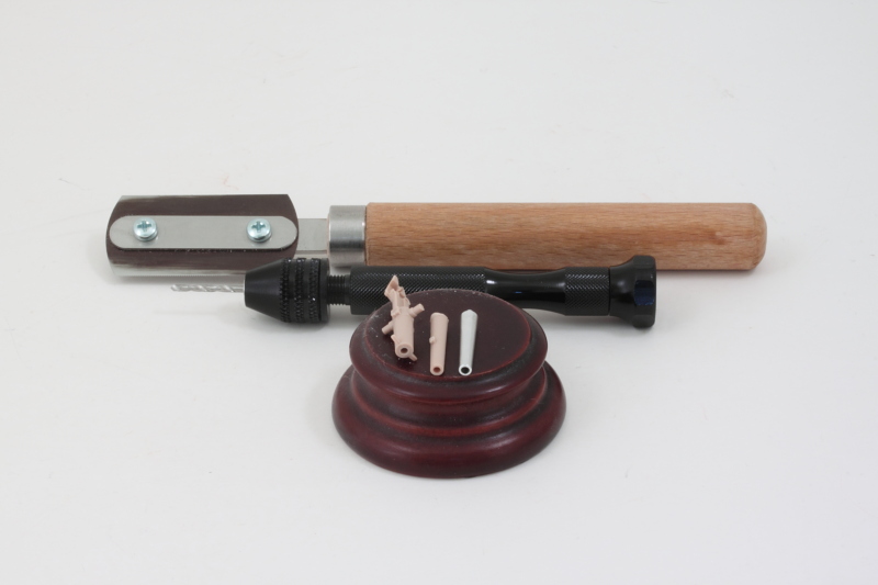
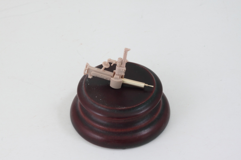
Today's efforts were all about the firepower on this beast! There are 6 water-cooled MGs that make up the secondary armament and Step 19 deals with their assembly. It's important to note that between the 6 total there are 4 that build up as type "A" and the other two are designated "B" and "C" since they use similar looking but slightly different parts. The biggest difference is that B and C are the rear-mounted pair and have different support posts but they also have different elevation mechanisms that are slightly shorter, so it pays to look carefully at the sprues and instructions throughout this process to avoid any problems.
Since the Aber barrel set includes replacements for the MGs, I needed to do some prep-work with them first before they could be used. The brass cooling jackets have a pre-drilled hole designed to take a short length of brass rod to create the mount points in the kit parts but the holes are slightly too small for the rod to fit easily into. I used a round needle file to clean out the holes on either side and then used a jeweler's hammer to literally hammer the rod into place to create the support pins for each one. Definitely no glue required to secure them in place! The length of rod included in the set is longer than needed but not a whole lot longer, so I had to be careful when and how I cut the pins to ensure I had enough to create all 6. The MG barrels and flash suppressors are separate little jewels with hollow muzzles and attached cleanly with just a touch of CA.
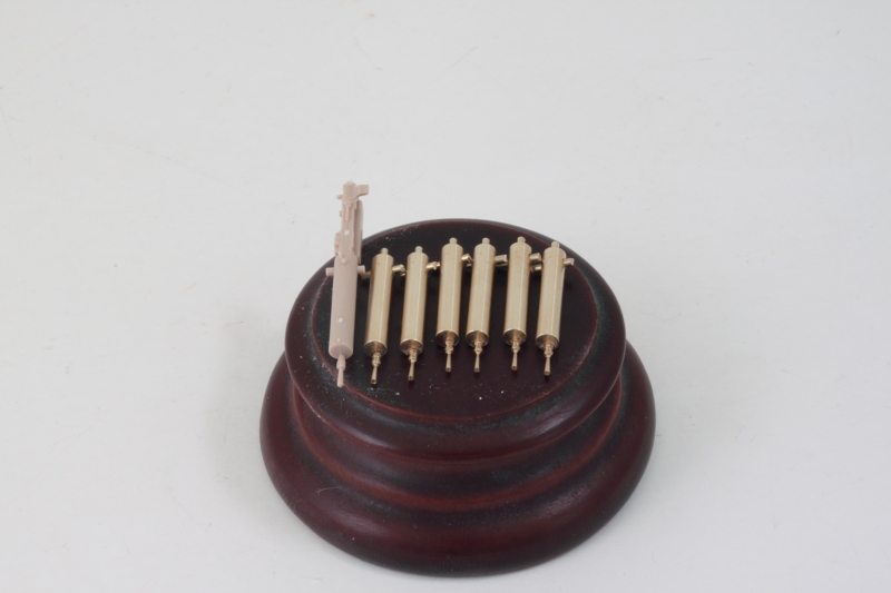
Getting those beautiful brass parts in place with the other mount components does take a little more work due to their added weight. Rather than attach the rest of the MG gun body to the barrel, I opted to trap the barrel in the swivel mount separately and assembled the rest of the gun body including the elevation support brace separate. The plastic parts are designed to work together to allow the guns to swivel in position but not elevate, so this approach allowed me to keep that function intact. I drilled out the mount hole for the brass barrel with a pin vise and then used CA gel to combine the two together along with the mount support post that will attach to the hull plate directly later on.

Once I had figured out how to get all the parts together and to play nice with each other, the end result was a single MG complete with its support post as a full unit. Since I'm not displaying the interior, I didn't bother with mounting the ammo belt, but it is worth noting that the length of the brass mounting pin requires a hole deep enough past the belt feed slot if the pin isn't trimmed shorter.
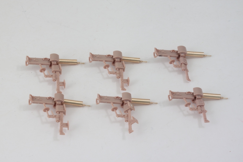
Rinse and repeat and before you know it, all 6 were done and ready to go for painting. I gave it my best shot to cut off the barrel detail from the kit parts and add it to the brass, but on my first attempt I managed to lose it to the carpet monster not 2 minutes after successfully gluing it in position. It's a good thing that happened on the first try and not the sixth I guess!
Next up will be doing some small work on the hull plates before breaking out the airbrush and doing some paint work on the lower hull and tracks.
Since the Aber barrel set includes replacements for the MGs, I needed to do some prep-work with them first before they could be used. The brass cooling jackets have a pre-drilled hole designed to take a short length of brass rod to create the mount points in the kit parts but the holes are slightly too small for the rod to fit easily into. I used a round needle file to clean out the holes on either side and then used a jeweler's hammer to literally hammer the rod into place to create the support pins for each one. Definitely no glue required to secure them in place! The length of rod included in the set is longer than needed but not a whole lot longer, so I had to be careful when and how I cut the pins to ensure I had enough to create all 6. The MG barrels and flash suppressors are separate little jewels with hollow muzzles and attached cleanly with just a touch of CA.
Getting those beautiful brass parts in place with the other mount components does take a little more work due to their added weight. Rather than attach the rest of the MG gun body to the barrel, I opted to trap the barrel in the swivel mount separately and assembled the rest of the gun body including the elevation support brace separate. The plastic parts are designed to work together to allow the guns to swivel in position but not elevate, so this approach allowed me to keep that function intact. I drilled out the mount hole for the brass barrel with a pin vise and then used CA gel to combine the two together along with the mount support post that will attach to the hull plate directly later on.
Once I had figured out how to get all the parts together and to play nice with each other, the end result was a single MG complete with its support post as a full unit. Since I'm not displaying the interior, I didn't bother with mounting the ammo belt, but it is worth noting that the length of the brass mounting pin requires a hole deep enough past the belt feed slot if the pin isn't trimmed shorter.
Rinse and repeat and before you know it, all 6 were done and ready to go for painting. I gave it my best shot to cut off the barrel detail from the kit parts and add it to the brass, but on my first attempt I managed to lose it to the carpet monster not 2 minutes after successfully gluing it in position. It's a good thing that happened on the first try and not the sixth I guess!
Next up will be doing some small work on the hull plates before breaking out the airbrush and doing some paint work on the lower hull and tracks.