Hobby Boss Sdkfz 222 Leichter Panzwerspahwagen 2cm (2015)
-
Bill Plunk
- Posts: 1245
- Joined: Wed Sep 28, 2022 10:18 pm
Hobby Boss Sdkfz 222 Leichter Panzwerspahwagen 2cm (2015)
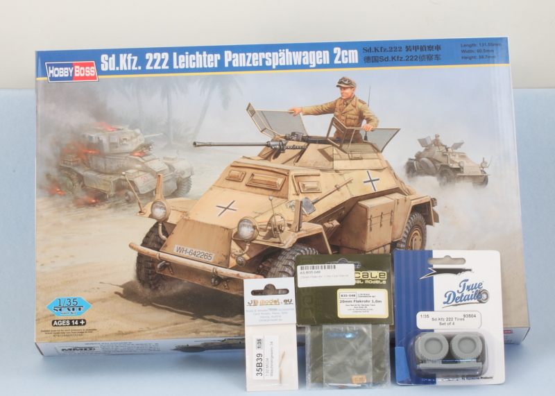
Build log for Hobby Boss kit #82442 Sdkfz 222 Leichter Panzerspahwagen 2cm with replacement barrels for the KwK 38 and MG34 and resin tires.
-
Bill Plunk
- Posts: 1245
- Joined: Wed Sep 28, 2022 10:18 pm
WIP 01-09-2015
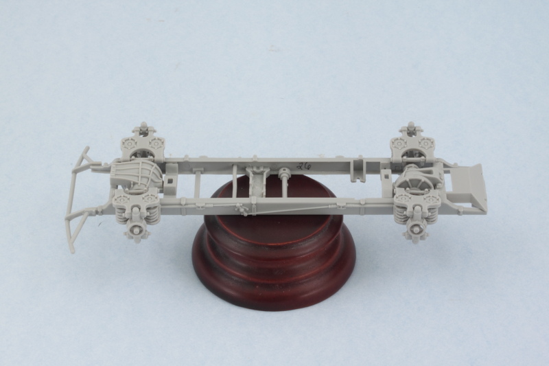
Got the wheels turning on this one and started in on Step 1 which deals with the chassis frame and various details. The front and rear drive elements get assembled first, each one has 6-8 parts and some clean-up is necessary on the drive halves in terms of flash, mold lines, etc. to get them together.
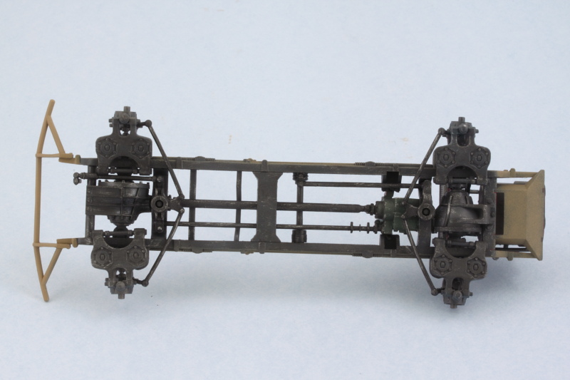
Then the real fun begins in terms of pairing up the two frame halves with all the different braces and other detail elements that go into the 'box'. It doesn't help that the tab fits for some of the brace components is a little loose, so you have to be patient and work from front to back to get it all together without gluing your fingers together or to the frames in the process. In the end though, it all comes together as intended. Ignore the number I wrote inside the right hull frame member...I got it backward when I wasn't paying attention and it doesn't matter regardless as the two parts are handed and can't be mixed up either way.
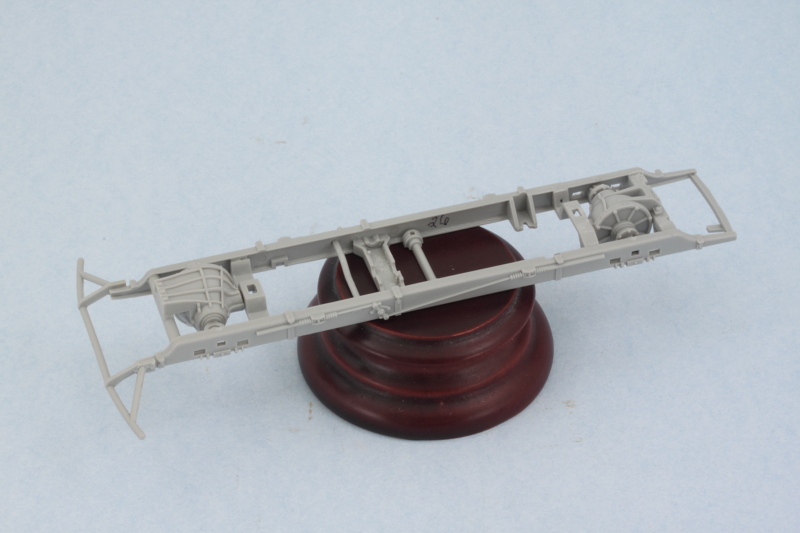
I did a quick check against the lower hull to make sure it was all lined up as it needed to be and will let that set up before moving on to the suspension elements which is another multi-part affair for the four wheels.
Then the real fun begins in terms of pairing up the two frame halves with all the different braces and other detail elements that go into the 'box'. It doesn't help that the tab fits for some of the brace components is a little loose, so you have to be patient and work from front to back to get it all together without gluing your fingers together or to the frames in the process. In the end though, it all comes together as intended. Ignore the number I wrote inside the right hull frame member...I got it backward when I wasn't paying attention and it doesn't matter regardless as the two parts are handed and can't be mixed up either way.
I did a quick check against the lower hull to make sure it was all lined up as it needed to be and will let that set up before moving on to the suspension elements which is another multi-part affair for the four wheels.
-
Bill Plunk
- Posts: 1245
- Joined: Wed Sep 28, 2022 10:18 pm
WIP 01-27-2015
Was able to get back to this one today and spent the afternoon continuing to work on the Step 1 requirements. Attention focused on the four suspension units. Each one consists of 6 separate parts and all of them have multiple sprue points, minor flash, and mold seams to clean up. The springs in particular required some special attention, I used the tip of a round needle file to remove the mold seam on the coils and clean up their separations.
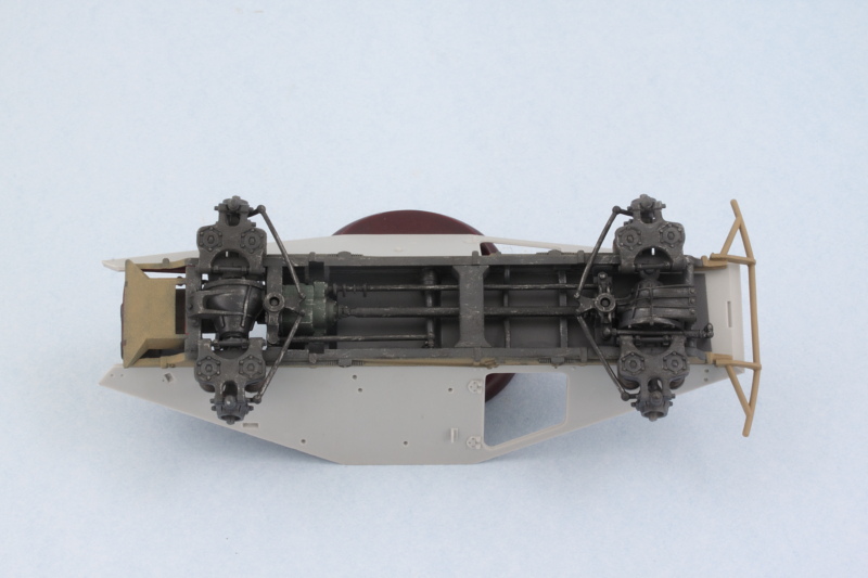
The location tabs for the springs and drive axles aren't a consistent or tight fit, so the assembly process requires some careful effort as a result. I added the spring coils first to the chassis frame, then added the top suspension frames (A1), followed by the bottom frames (A21). I used the wheel hub supports (A16) to ensure the top and bottom frames were lined up properly but didn't glue them in place just yet. Instead I let the glue set up on the frames and then popped out the supports so I could add the axles (these can't slide through the supports) and get them properly centered. They fit loosely in their mount holes so I had to hold them for a minute or two until the glue grabbed. Then the supports went back on and were glued in place permanently.
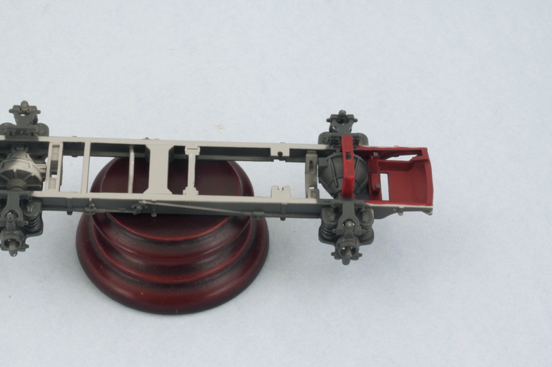
A lot of work (and explanation!) but here's where things now stand at the end of Step 1.
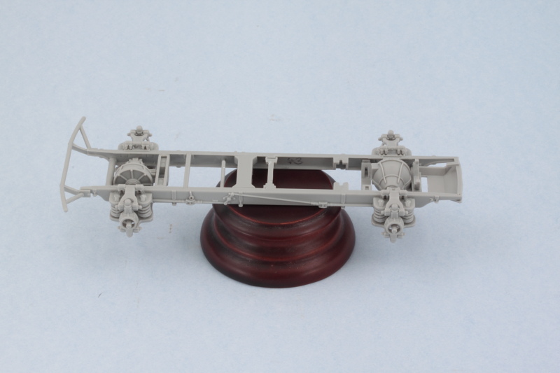
It's a pretty detailed set-up but delicate until everything sets up, so that's all for now. Next up will be working on the engine and transmission in Step 2.
The location tabs for the springs and drive axles aren't a consistent or tight fit, so the assembly process requires some careful effort as a result. I added the spring coils first to the chassis frame, then added the top suspension frames (A1), followed by the bottom frames (A21). I used the wheel hub supports (A16) to ensure the top and bottom frames were lined up properly but didn't glue them in place just yet. Instead I let the glue set up on the frames and then popped out the supports so I could add the axles (these can't slide through the supports) and get them properly centered. They fit loosely in their mount holes so I had to hold them for a minute or two until the glue grabbed. Then the supports went back on and were glued in place permanently.
A lot of work (and explanation!) but here's where things now stand at the end of Step 1.
It's a pretty detailed set-up but delicate until everything sets up, so that's all for now. Next up will be working on the engine and transmission in Step 2.
-
Bill Plunk
- Posts: 1245
- Joined: Wed Sep 28, 2022 10:18 pm
WIP 01-31-2015
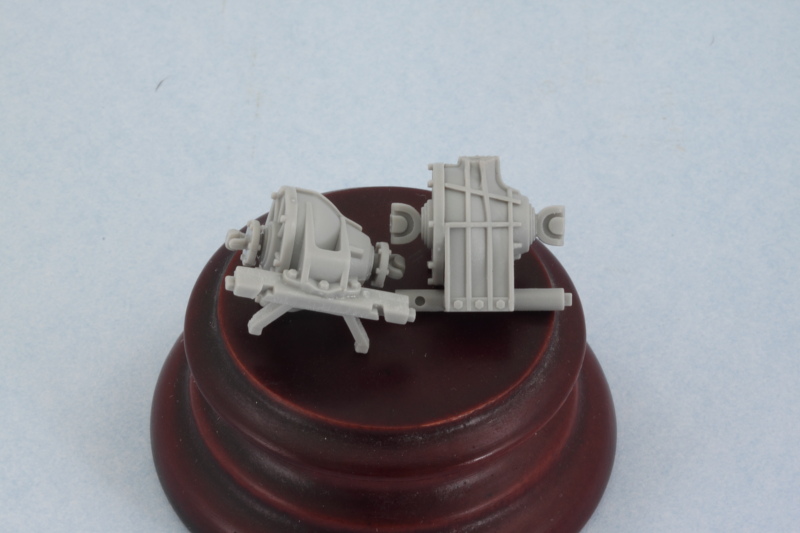
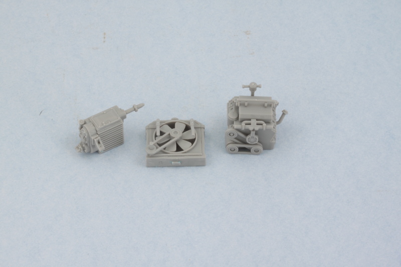
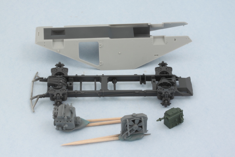
Continuing on with the interior drive-train components, Step 2 deals with the transmission and Horch V8 3.5L engine. There's a lot of small parts that go into both of these and of course they need to connect up to each other just so to line up properly. The connecting shaft B51 I left for last to make sure I wouldn't have any problems and did a dry-fit on the chassis and let the glue set up solidly on the transmission end of the shaft as the fit there is a little loose.
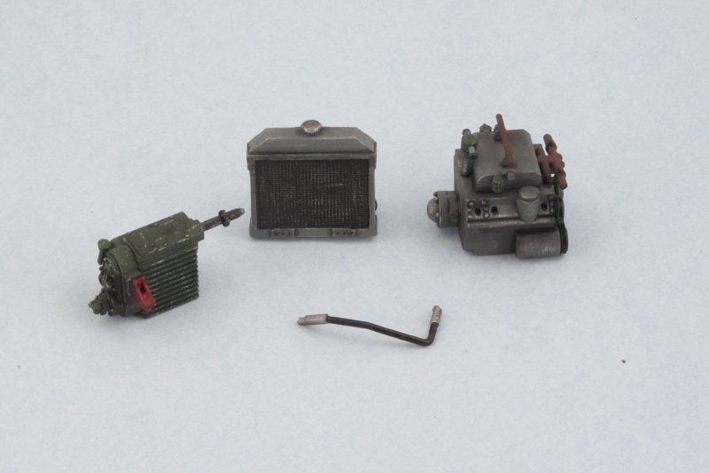
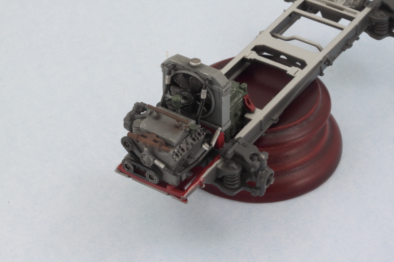
The third component is the radiator, this is assembled in Step 3. The hoses and fan belt drive need to line up with the engine in specific places but there aren't any guides or locater holes to help with this, so careful fit and dry-fit with the engine in the chassis was necessary to ensure they were all at the right angles and would set properly for later installation.
All 3 pieces are fully assembled and awaiting paint/detailing. As usual along the way, some of the fit tabs or holes needed to be trimmed or slightly enlarged to allow for proper connections, so test-fits with these components is essential at every step before committing to glue.
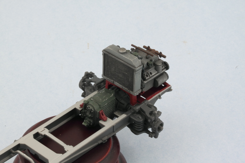
I used some small blobs of poster blue-tack putty to check the fit of all the components throughout when I needed things to stay put and allow glue to set. Here's the latest combo/mock-up with all the components in the positions they will occupy once fully installed.
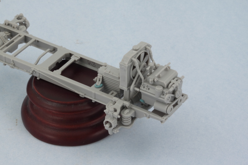
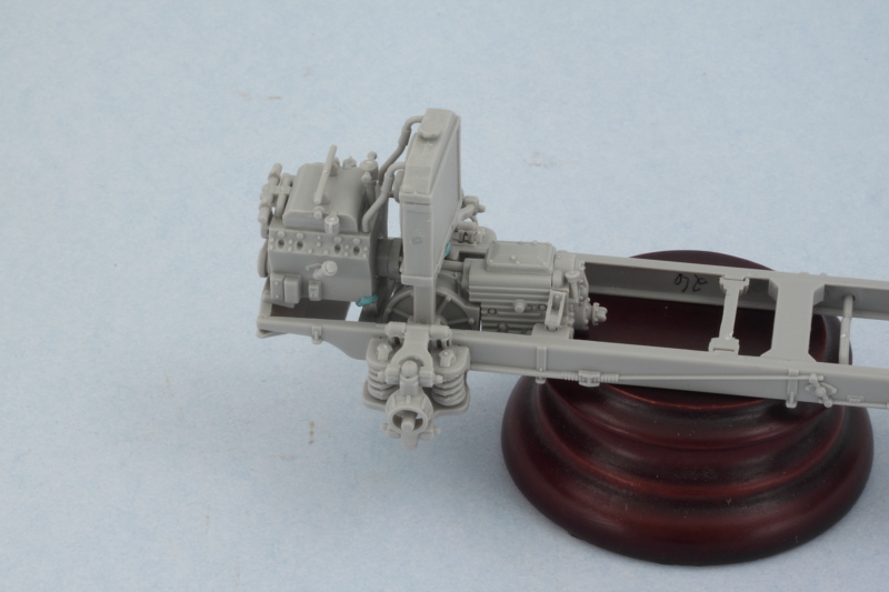
A quick test-fit with the lower hull shows that the transmission is going to be largely hidden away except for some visibility from the hull underside. Everything fits together as it should for the space available, always a good sign. Only the radiator is going to be visible through the separating grate inside the fighting compartment looking back though once the upper hull is added.
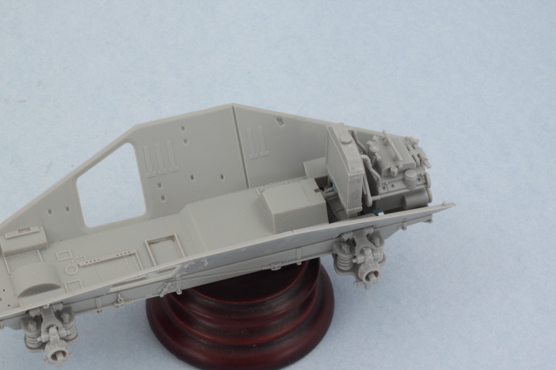
Good chunks of the engine will still be visible with the upper hull in place via the various engine compartment hatches though. Not sure just yet how many (if any) of these I will actually open up.
Next up will be spending some time detail painting these areas and getting it ready before I can shift attention to the hull interior proper. The chassis and engine/transmission components are almost a kit in themselves in terms of the level of detail they include.
The third component is the radiator, this is assembled in Step 3. The hoses and fan belt drive need to line up with the engine in specific places but there aren't any guides or locater holes to help with this, so careful fit and dry-fit with the engine in the chassis was necessary to ensure they were all at the right angles and would set properly for later installation.
All 3 pieces are fully assembled and awaiting paint/detailing. As usual along the way, some of the fit tabs or holes needed to be trimmed or slightly enlarged to allow for proper connections, so test-fits with these components is essential at every step before committing to glue.
I used some small blobs of poster blue-tack putty to check the fit of all the components throughout when I needed things to stay put and allow glue to set. Here's the latest combo/mock-up with all the components in the positions they will occupy once fully installed.
A quick test-fit with the lower hull shows that the transmission is going to be largely hidden away except for some visibility from the hull underside. Everything fits together as it should for the space available, always a good sign. Only the radiator is going to be visible through the separating grate inside the fighting compartment looking back though once the upper hull is added.
Good chunks of the engine will still be visible with the upper hull in place via the various engine compartment hatches though. Not sure just yet how many (if any) of these I will actually open up.
Next up will be spending some time detail painting these areas and getting it ready before I can shift attention to the hull interior proper. The chassis and engine/transmission components are almost a kit in themselves in terms of the level of detail they include.
-
Bill Plunk
- Posts: 1245
- Joined: Wed Sep 28, 2022 10:18 pm
WIP 02-03-2015
The chassis had gotten to the point where I needed to do some paint work with it before I could go any further. Since I hate to scrape paint and the contact surfaces for the chassis to the lower hull aren't that large, I masked off the necessary areas on the lower hull and chassis with blue painter's tape to get everything ready. The engine, transmission, and radiator were also suitably prepped before heading over to the paint booth.
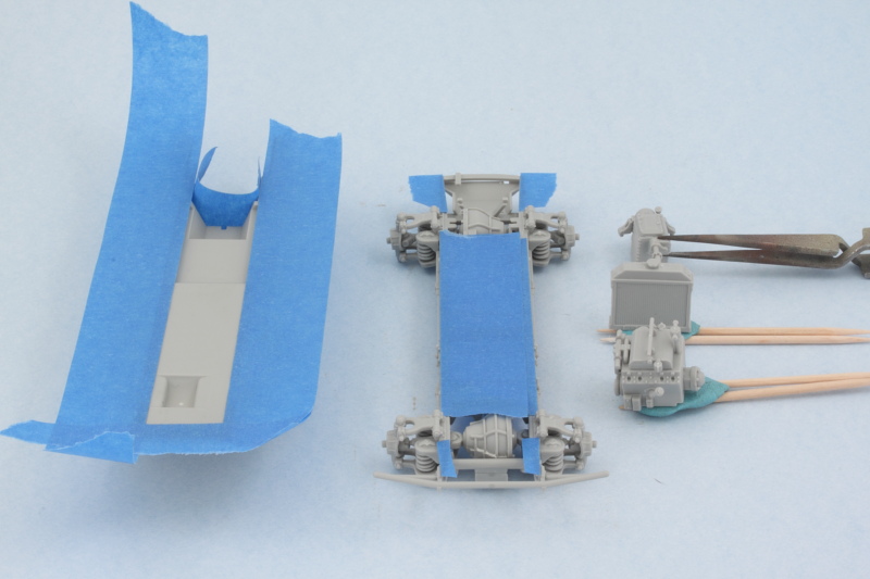
The only markings options in the kit are for DAK vehicles, so I opted to go the route for a vehicle with the 21st Panzer Division in Libya during May 1941. That means the vehicle would've originally been in panzer gray before being repainted in the field, so to reflect that the chassis and hull undersides were given a dose of Testor's Model Master enamel Panzer Schwarzgrau with the airbrush. The engine and radiator were airbrushed with a lighter gray primer mix that I keep on hand and the transmission got a green primer coat using MM enamel Khaki for a little variety.
Later on when the chassis and lower hull are joined up there will need to be some small touch-ups to the Panzer Gray areas but that's not a huge deal. Much more important that the hull and chassis have a clean surface for gluing. Some of the area at the front will be painted over once it comes time to apply a Tropen scheme. Once the paint fully cures I can move on to the detail work for this little 'mini-kit' portion of the build.
-
Bill Plunk
- Posts: 1245
- Joined: Wed Sep 28, 2022 10:18 pm
WIP 02-10-2015
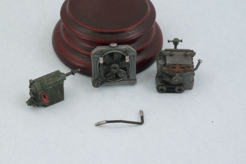
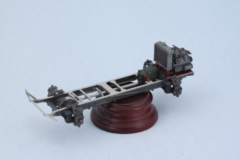
Work continued today on getting the drive-train components detailed and ready for installation. First up was getting some red oxide on the radiator mount and engine tray area. Most of this will get hidden away but enough is visible that it's worth detailing for visual interest at a minimum.
Building on the airbrush work from earlier, I hand detailed and weathered the transmission, radiator, and engine. At first I thought the kit had left out the coolant water return hose but for some reason they just waited to include it in Step 7 as part B39. There's no real reason I can see for doing that...a test fit of the hose in place still allows the hull body to be slid into position with no issues, so I went ahead and painted it up and got it ready. Maybe it was just easier to slip it in on Step 7 since the diagram was already aligned for that area to view...hard to say!
So with all the paint work out of the way, time to install. Transmission went in place first, followed by the radiator mount (the earlier shot only had it test fit), then the engine, and lastly the radiator itself and the return water hose. All of the connection points are kind of delicate or small, so it's essential to let the glue set and avoid anything shifting around in the process.
Speaking of that, I also cleaned up the main drive axle and did a test fit with the front of the chassis and the transmission. The length of the shaft part is just a little too long, so I had to sand it down slightly at the vehicle's front end so it would fit properly. It did cause the transmission to shift slightly while the glue was setting on the process mentioned above...so a quick recheck showed everything was still sitting properly and I'll leave the shaft dry-fit in place for now until the glue sets up fully overnight before adding the rest of the suspension components to the chassis.
-
Bill Plunk
- Posts: 1245
- Joined: Wed Sep 28, 2022 10:18 pm
WIP 02-15-2015
Spent some more time on the chassis getting it all finished up today. First order of business involved airbrushing some MM enamel Afrika Grunbraun (RAL 8000) to the chassis sides, front bumper, and rear hull areas that would've gotten an over-paint treatment while leaving the rest of the underside in the original Panzer Gray. I used the previous Panzer Schwarzgrau base to allow for a little pre-shading as well and strips of blue painter's tape helped mostly keep the paint only to the areas I wanted it.
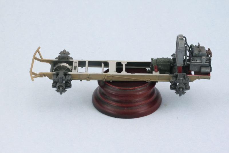
Next I worked on the suspension spring coils to pick them out and add a little more detail. While it's hard to pick up in the photos, in hand the effect is very similar to what I got on the engine block exhaust manifolds. I used a base of MM non-buffing Metalizer Gunmetal, lightly dry brushed some MM enamel Steel, then applied a wash of thinned MM enamel Leather and a light dusting of some rust colored artist pastels.
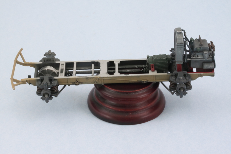
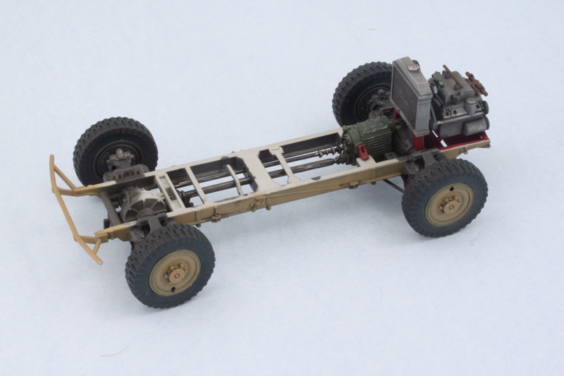
Getting the drive shaft and steering elements in place is a bit of an exercise. The instruction diagrams are a little vague in spots so it's necessary to study it a bit to get it all in place. These components were hand painted first and then installed to get it all together. Base of non-buffing Metalizer Gunmetal followed by some lightly dry brushed enamel Steel.
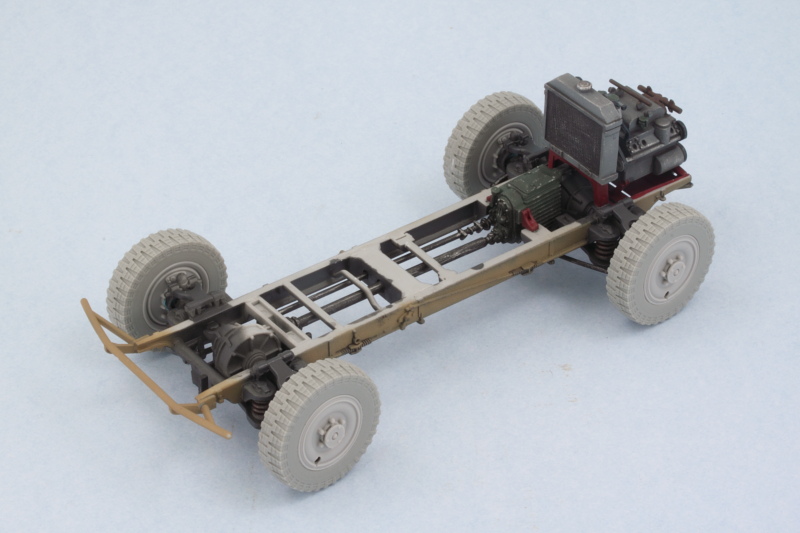
And just for fun, here's how it's all stacking up so far when dry-fitted to the lower hull.
Onward and upward!
Next I worked on the suspension spring coils to pick them out and add a little more detail. While it's hard to pick up in the photos, in hand the effect is very similar to what I got on the engine block exhaust manifolds. I used a base of MM non-buffing Metalizer Gunmetal, lightly dry brushed some MM enamel Steel, then applied a wash of thinned MM enamel Leather and a light dusting of some rust colored artist pastels.
Getting the drive shaft and steering elements in place is a bit of an exercise. The instruction diagrams are a little vague in spots so it's necessary to study it a bit to get it all in place. These components were hand painted first and then installed to get it all together. Base of non-buffing Metalizer Gunmetal followed by some lightly dry brushed enamel Steel.
And just for fun, here's how it's all stacking up so far when dry-fitted to the lower hull.
Onward and upward!
-
Bill Plunk
- Posts: 1245
- Joined: Wed Sep 28, 2022 10:18 pm
WIP 02-17-2015
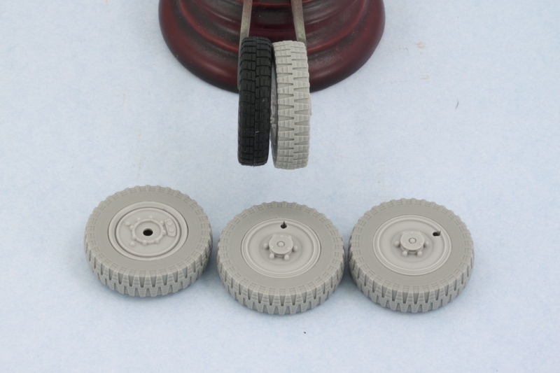
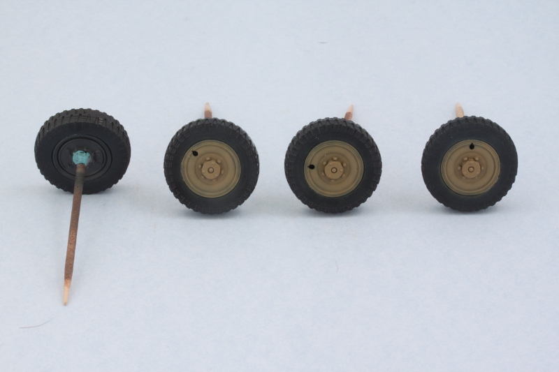
Had some time today so I devoted some attention to the wheels. The True Details resin tires needed some clean-up to remove the interior circles from the casting process and their pour stubs removed of course as well. Test fits with the kit's wheel hubs showed that some additional fine trimming and sanding with a round needle file was necessary to further adjust the inner diameter to allow the hub halves to snap into position. Not quite a drop fit but not a huge effort required either to get everything to play nice. Just a case of lots of small adjustments back and forth with each one until the fit was just right.
Of course, since I wasn't using the flexible vinyl tires, the hub halves need to be left separate and not joined together as called for in the instructions. Right now they are just dry fit in position (by not adding the little cap, part A20, it's possible to push the front hubs back out through the axle hole in the rear hub) and will be permanently installed once painted. The resin tires are slightly wider than the kit tires to allow both the inner and outer hubs to fit correctly flush up against the tire and of course don't have the vinyl seam down the middle. Since vehicles in N. Africa typically didn't have the triangular armored hub covers, I left those off for consistency with the vehicle I'm modeling.
A quick test fit with the aid of some blue-tack poster putty shows everything's playing nice and sitting level, always a good sign!
Next up will be getting some paint on those wheels and tires and then setting them off to the side. I don't want to install them permanently until after I've got the hull and chassis together to make sure I can make any minor adjustments needed down the road to ensure a level set to the whole vehicle.
-
Bill Plunk
- Posts: 1245
- Joined: Wed Sep 28, 2022 10:18 pm
WIP 02-22-2015
Did some airbrush work on the wheels and tires. For the rubber portions, I used Testors enamel Gunmetal first with the hubs snapped in place to help mask off the interior surfaces. Then some enamel Panzer Schwarzgrau on both the inner and outer hubs and lastly some Afrika Grunbraun for the outer hubs over the Schwarzgrau. Popped the hubs out and carefully corrected any over-spray on the rubber areas and voil�! Tires and wheels painted. Toothpicks and small blobs of blue tack made it easy to handle them and also mask off the connection points on the rear hubs.
The wheels and tires will get more weathering and detailing down the road and are only dry fit for now, but the chassis portion of the build is now complete!
The wheels and tires will get more weathering and detailing down the road and are only dry fit for now, but the chassis portion of the build is now complete!
-
Bill Plunk
- Posts: 1245
- Joined: Wed Sep 28, 2022 10:18 pm
WIP 02-24-2015
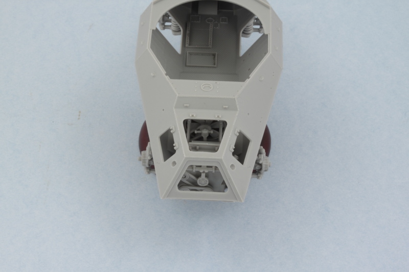
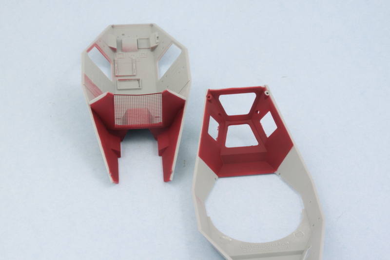
I started work on the interior for the hull today. Having been forewarned about possible fit issues with the rear bulkhead that separates the fighting compartment from the engine compartment, I skipped ahead a bit to Step 5 to deal with that. After some test fits and some slight sanding on the lower edges and a bit of trimming at the very top portions to get everything lined up properly, I decided the best route was to go ahead and install the bulkhead into the lower hull now. I also needed to putty and sand some rather large ejector marks that are on the interior side of the bulkhead before I could do the installation. Some careful applications of liquid glue around the lower edges and finger pressure did the trick to ensure the bulkhead didn't flex at the top until the glue could grab hold.
I then used the upper hull to help hold things in place so the glue could set up permanently and hold the bulkhead in the proper position. A rubber band at the hull nose helped keep the hull halves together as they only have locating pins at the front and rear. Then I added the PE mesh screen last since it had an alarming tendency to bow at the top along with the bulkhead top edges since there wasn't any frame or support there to keep it straight or rigid.
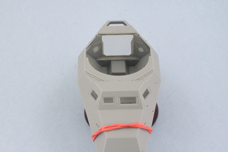
Once that had set up, I could now paint the engine compartments. I airbrushed my Red Oxide mix after carefully masking off the mating edges on the different hull portions.
A quick test fit with the chassis and engine shows everything still continuing to play nice with each other, always a good thing.
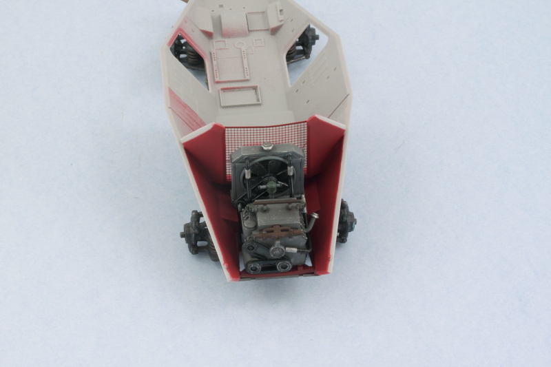
I'll weather up the engine bay a little bit after the red oxide has cured but won't go overboard here since the vast majority of it will disappear from view once the hull halves are joined together.
I then used the upper hull to help hold things in place so the glue could set up permanently and hold the bulkhead in the proper position. A rubber band at the hull nose helped keep the hull halves together as they only have locating pins at the front and rear. Then I added the PE mesh screen last since it had an alarming tendency to bow at the top along with the bulkhead top edges since there wasn't any frame or support there to keep it straight or rigid.
Once that had set up, I could now paint the engine compartments. I airbrushed my Red Oxide mix after carefully masking off the mating edges on the different hull portions.
A quick test fit with the chassis and engine shows everything still continuing to play nice with each other, always a good thing.
I'll weather up the engine bay a little bit after the red oxide has cured but won't go overboard here since the vast majority of it will disappear from view once the hull halves are joined together.