Dragon Jagdpanzer IV L/70(V) (2015)
-
Bill Plunk
- Posts: 1245
- Joined: Wed Sep 28, 2022 10:18 pm
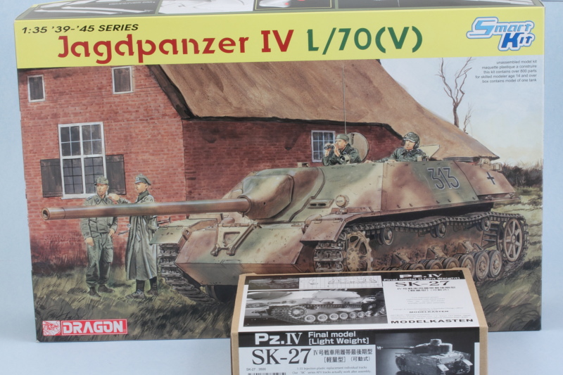
Dragon Jagdpanzer IV L/70(V) (2015)
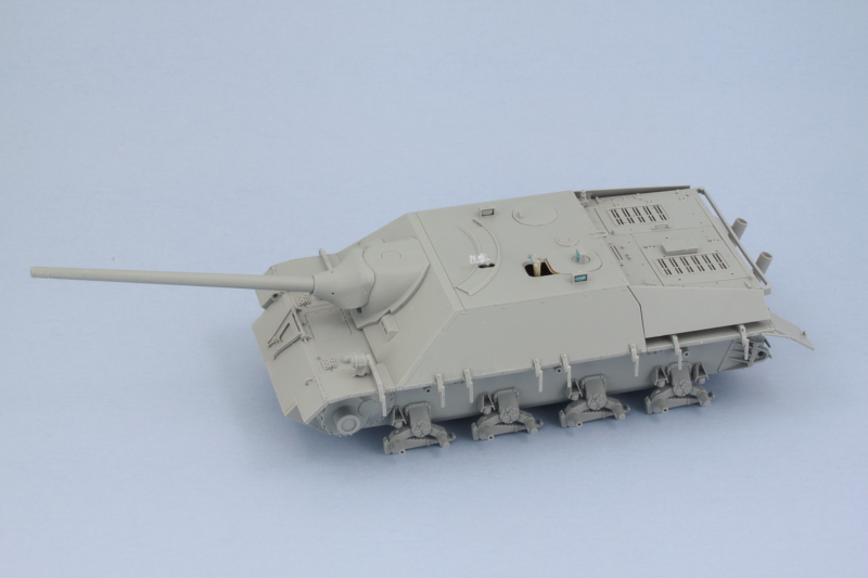
Build log for Dragon's 1/35 kit #6397 Jagdpanzer IV L/70(V) with Model Kasten workable tracks.
-
Bill Plunk
- Posts: 1245
- Joined: Wed Sep 28, 2022 10:18 pm
WIP 05-12-2015
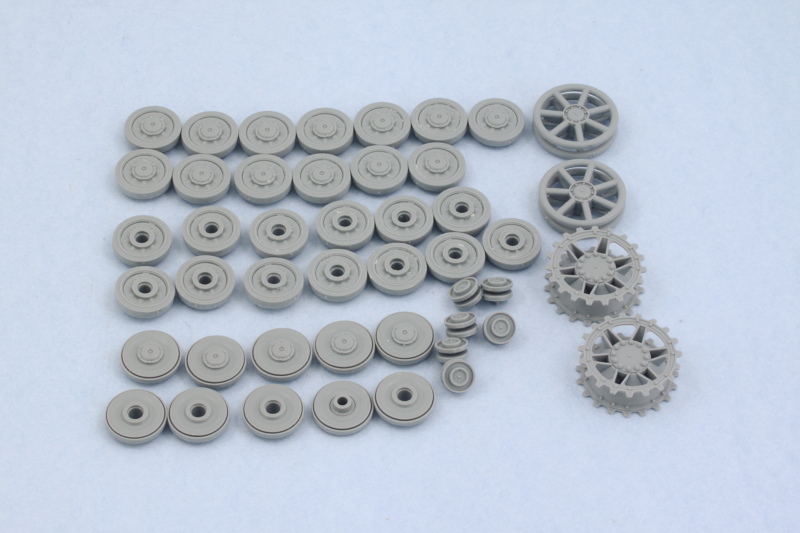
Every kit has to start somewhere and with a Dragon kit that's usually the road wheels! Step 1 calls for the assembly of the wheels, sprockets, idlers, and return rollers. Since I'm going to be building a vehicle built early on (pre-Nov. 1944) in the production run, I opted for the A14-A13 style of return rollers. I left all the road wheel halves unassembled for now so it will be easier to paint them later and sanded down the mold seams on all but the spare rubber-rim wheel pair that installs on the engine deck. The kit also provides a spare steel-rim wheel, so I assembled 5 of them as well. Dragon employs a 3-part process to build up each wheel half that provides a really nice result for this type of wheel but does take a little care when cleaning up the parts and gluing them together. So with that, we're off!
-
Bill Plunk
- Posts: 1245
- Joined: Wed Sep 28, 2022 10:18 pm
WIP 05-23-2015
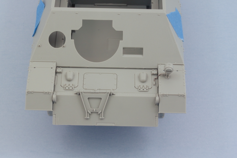
As is often the case with Dragon kits, it pays to skip around a bit in the instructions. The latest round of effort focused on getting the main hull components in place starting with the rear hull plate. Step 2 would have you put all the details on the plate first and then install it, but that's not really a good idea. You do have to choose your style of exhaust though in this step and this choice impacts all the other options that should go on the vehicle in subsequent steps. Since I'm depicting a vehicle produced in the Oct-Nov window, I chose the vertical tube exhausts and worked with the corresponding plate and details that match it. Having built previous kits of the Pz IV family from Dragon, I know it's also a good idea to assemble and add the idler housings to the plate first vs. trying to add them after the plate is installed to the hull like the instructions want you to do in Step 3.
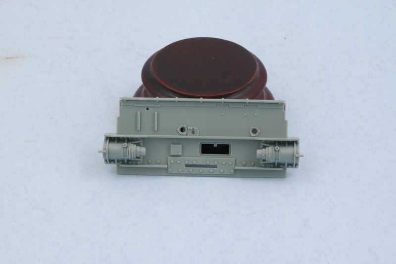
Once that's done, the rear plate was installed along with the glacis plate from Step 3 and the brake access hatch plate from Step 4-5. Just like with the rear plate, I deliberately left the details off the brake hatch plate to make it easier to install. A little bit of finger pressure from underneath the plate is needed to make sure it lines up evenly with the glacis plate, otherwise it has a tendency to want to sag a bit in the middle. The fighting compartment bulkhead from Step 5 was also added to ensure everything lined up properly and the hull keeps its rigidity.
That allowed me to circle back and complete the details from Step 2 for the rear hull plate. It's a good idea to add the H24/H25 combo parts first as they influence how the left exhaust tube lines up. The stacks themselves are a little tricky to get together since a PE plate is used as the base for the stacks and the tops for the support trays. I found it easiest to glue the PE plate to the tube exhaust first and then line it up with the tray as the bend in the pipe that connects to the hull makes that a tight fit if you attach the plate to the tray first. In keeping with my Oct-Nov production vehicle, I opted for the standard Pz IV type of rear tow hitch to round things out. The instructions in Step 3 have a part number error, the base of the hitch is actually B54 and not H54.
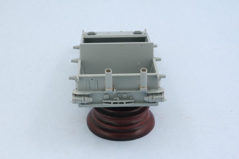
Next up will be the hull side details and the suspension elements.
Once that's done, the rear plate was installed along with the glacis plate from Step 3 and the brake access hatch plate from Step 4-5. Just like with the rear plate, I deliberately left the details off the brake hatch plate to make it easier to install. A little bit of finger pressure from underneath the plate is needed to make sure it lines up evenly with the glacis plate, otherwise it has a tendency to want to sag a bit in the middle. The fighting compartment bulkhead from Step 5 was also added to ensure everything lined up properly and the hull keeps its rigidity.
That allowed me to circle back and complete the details from Step 2 for the rear hull plate. It's a good idea to add the H24/H25 combo parts first as they influence how the left exhaust tube lines up. The stacks themselves are a little tricky to get together since a PE plate is used as the base for the stacks and the tops for the support trays. I found it easiest to glue the PE plate to the tube exhaust first and then line it up with the tray as the bend in the pipe that connects to the hull makes that a tight fit if you attach the plate to the tray first. In keeping with my Oct-Nov production vehicle, I opted for the standard Pz IV type of rear tow hitch to round things out. The instructions in Step 3 have a part number error, the base of the hitch is actually B54 and not H54.
Next up will be the hull side details and the suspension elements.
-
Bill Plunk
- Posts: 1245
- Joined: Wed Sep 28, 2022 10:18 pm
WIP 05-25-2015
Latest round of effort dealt with the lower hull suspension components and the left over details for the brake hatch plate. Even though the instructions don't indicate this in Step 4, it's possible to assemble and install the gun travel lock and have it remain workable. The key is to only glue the base hinge points G12/G13 into the hull after you've dry fit them in position and slipped the pins of the lock into them so that it will remain workable. The main benefit this provides is making life easier for painting/finishing the nose area later on and, of course, giving you the option of posing the lock if you like. I also added the suspension bump stops and final drive housings as called for in Step 5.
Step 6 assembles and installs the suspension bogeys. These are handed and the parts are designed to make it impossible to mix them up, but it still pays to work only on one side at a time to avoid any glue mishaps. Some of the suspension pairs had some flash on the hinge point where they meet up with the base parts and a triangular needle file helped eliminate that and ensure they fit properly. The suspension is fixed and non-workable unfortunately but not a big deal for my purposes.
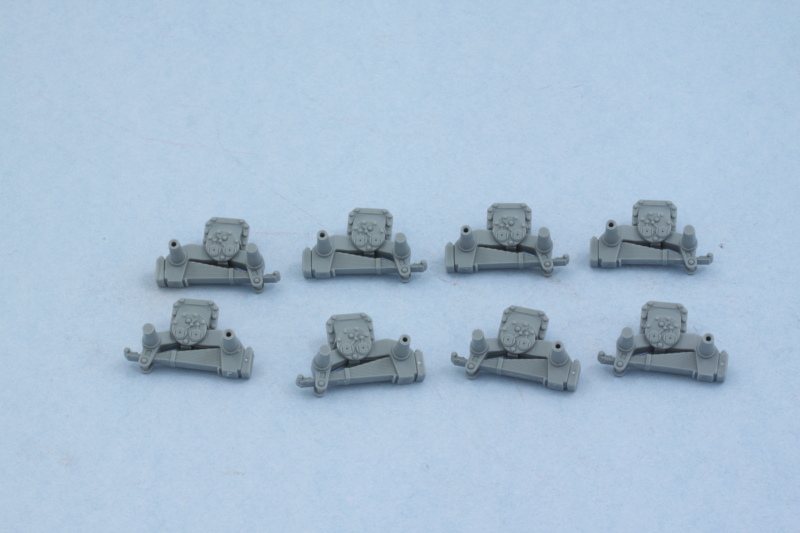
Once all the components were ready, they were installed on both sides. Small adjustments were needed to get them to line up properly and I used small amounts of blue tack poster putty to hold single road wheels in place to ensure a level set while the glue grabs. This avoids the possibility of 'floating' road wheels when it comes time to install them later.
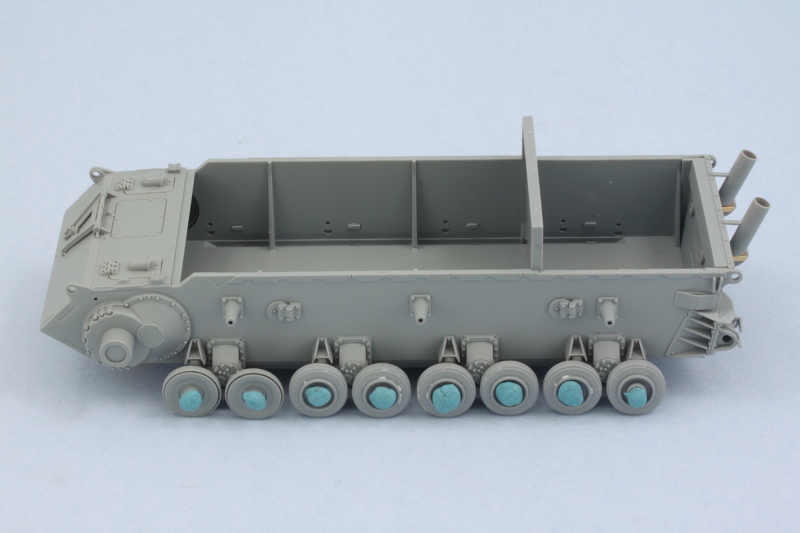
Next up will be moving to the upper hull and dealing with the fenders and engine deck.
Step 6 assembles and installs the suspension bogeys. These are handed and the parts are designed to make it impossible to mix them up, but it still pays to work only on one side at a time to avoid any glue mishaps. Some of the suspension pairs had some flash on the hinge point where they meet up with the base parts and a triangular needle file helped eliminate that and ensure they fit properly. The suspension is fixed and non-workable unfortunately but not a big deal for my purposes.
Once all the components were ready, they were installed on both sides. Small adjustments were needed to get them to line up properly and I used small amounts of blue tack poster putty to hold single road wheels in place to ensure a level set while the glue grabs. This avoids the possibility of 'floating' road wheels when it comes time to install them later.
Next up will be moving to the upper hull and dealing with the fenders and engine deck.
-
Bill Plunk
- Posts: 1245
- Joined: Wed Sep 28, 2022 10:18 pm
WIP 05-28-2015
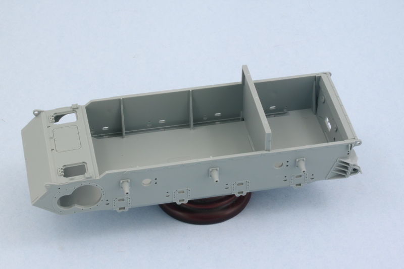
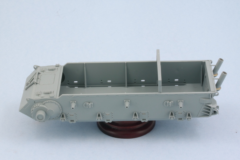
Moving on to the upper hull and fenders requires a delicate balancing act between a lot of components that all have to play nice with each other front to back so that the casemate and engine deck line up with each other as well as the fenders and lower hull. To that end, I started with the fenders first as called for in Step 7 but assembled them a little differently than the instructions would have you do it. I left off the front and rear mud guards and only glued the middle portions of the fenders down to the hull as this is where they have the most 'grip' while still leaving some flexibility to line up the front and back portions as needed to keep things straight and level. Then the guards were added front and back along with their appropriate details. The casemate was taped into position throughout to make sure that the fenders didn't bow out at the edges to also help things along. Have to be careful not to get any glue on it though as it has to remain loose to allow the gun to be installed later on.
I also added the missing wiring for the Bosch headlight using some 0.5mm solder and a #76 finger drill to open up the base of the light and the armored hump on the hull plate that the conduit feeds into.
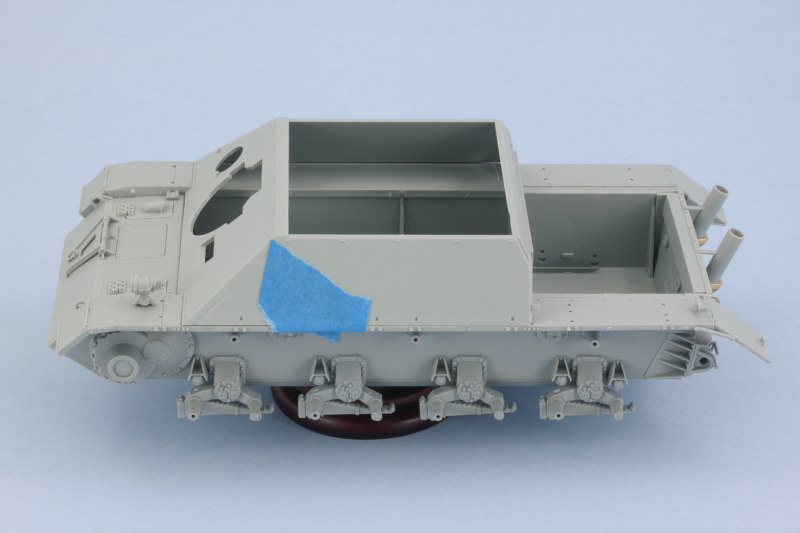
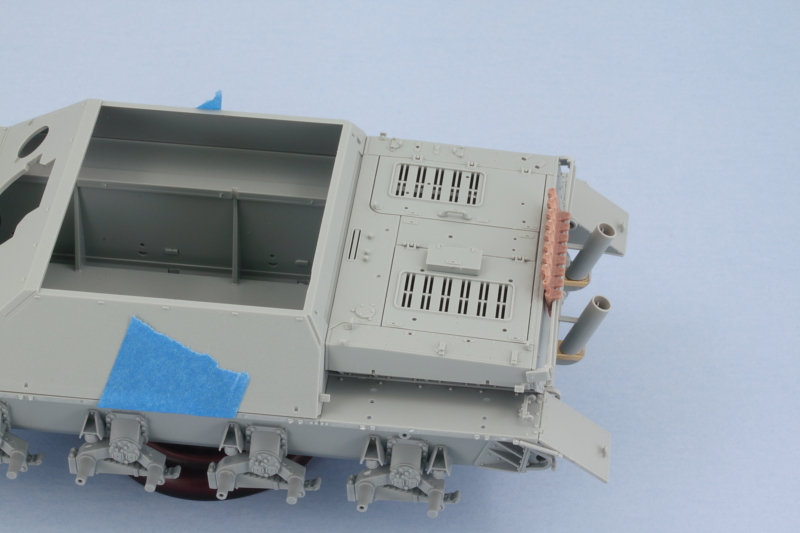
With the fenders out of the way, attention turned to the engine deck. This is covered in steps 8-10 but I don't recommend you follow the instruction order for getting the deck together or you might encounter fit issues with the lower hull. The instructions would have you assemble the entire deck and then set it off to the side and not add it until Step 18 when it calls for it to go in along with the complete casemate. The problem with this approach is that the intake sides are a very snug fit into the available opening and slots with the lower hull bulkhead, fenders, etc. If the full engine deck is assembled, it's almost impossible to 'flex' these properly to get them to line up correctly. So the solution is to only add the intake sides to the top of the engine deck and then install those onto the fenders and lower hull. I also found after doing some test fits that I needed to sand down the rear edges of the tow hook extensions as they have some interference with the rear engine deck plate and this also has to be done at this point before the deck is installed or you can't get at them to make the correction.
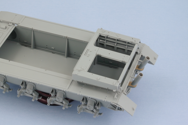
Careful use of glue on the deck means you can also use the casemate to ensure the deck lines up correctly and aligns as it should. Once the glue had set, I added the appropriate rear plate, B28, for the long spare track rack. The other optional plate with a shorter rack is meant for vehicles equipped with the large cylinder exhaust type, so it's important to choose the right one. Because the long rack has some flex to it, I used a short run of 8 links of MK tracks to help it hold its shape while the glue set and ensure I wouldn't have problems fitting the spare track run later on. Rounding out things here I also added the two large engine deck hatches and their details but left off all the tools and equipment as it will get added after the vehicle has received its paint and camo schemes.
Up next will be working on the gun and casemate.
I also added the missing wiring for the Bosch headlight using some 0.5mm solder and a #76 finger drill to open up the base of the light and the armored hump on the hull plate that the conduit feeds into.
With the fenders out of the way, attention turned to the engine deck. This is covered in steps 8-10 but I don't recommend you follow the instruction order for getting the deck together or you might encounter fit issues with the lower hull. The instructions would have you assemble the entire deck and then set it off to the side and not add it until Step 18 when it calls for it to go in along with the complete casemate. The problem with this approach is that the intake sides are a very snug fit into the available opening and slots with the lower hull bulkhead, fenders, etc. If the full engine deck is assembled, it's almost impossible to 'flex' these properly to get them to line up correctly. So the solution is to only add the intake sides to the top of the engine deck and then install those onto the fenders and lower hull. I also found after doing some test fits that I needed to sand down the rear edges of the tow hook extensions as they have some interference with the rear engine deck plate and this also has to be done at this point before the deck is installed or you can't get at them to make the correction.
Careful use of glue on the deck means you can also use the casemate to ensure the deck lines up correctly and aligns as it should. Once the glue had set, I added the appropriate rear plate, B28, for the long spare track rack. The other optional plate with a shorter rack is meant for vehicles equipped with the large cylinder exhaust type, so it's important to choose the right one. Because the long rack has some flex to it, I used a short run of 8 links of MK tracks to help it hold its shape while the glue set and ensure I wouldn't have problems fitting the spare track run later on. Rounding out things here I also added the two large engine deck hatches and their details but left off all the tools and equipment as it will get added after the vehicle has received its paint and camo schemes.
Up next will be working on the gun and casemate.
-
Bill Plunk
- Posts: 1245
- Joined: Wed Sep 28, 2022 10:18 pm
WIP 05-30-2015
Latest round of effort moved to the casemate and gun as called for in Steps 11-14. The breech and recoil guards are dealt with in Step 11 and Step 12 adds the mount details, gun barrel, gunner's sight, and the elevation and traverse wheels. It all goes together without any issues and the gun remains able to elevate via friction connection with a toothed gear that slips inside the left side of the gun mount support. Just make sure you insert the gun barrel and breech through the recoil guards and ball mount before adding the back pad, G6, to the recoil guards.
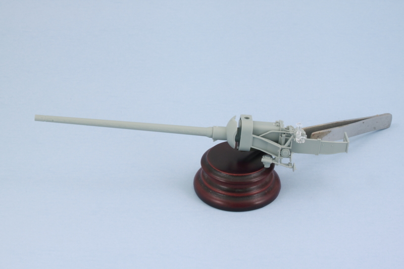
Step 13 is a pretty simple step, it adds the interior plate to the front of the casemate along with the exhaust fan and the mount for the hull MG port. No gun is provided though, just the simple ball mount and tray for one is present. The little ball tray is numbered wrong in the instructions, it's actually C23 and not C22. Last but not least for this step is the addition of the clear periscopes for the driver.
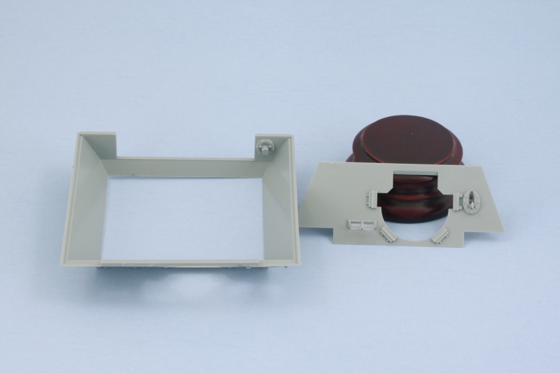
Step 14 is the moment of truth when the whole gun is installed along with the cast external mantlet components. This almost requires three hands to get it all together and still allow the gun to traverse slightly. You also have to avoid gluing the base of the mount, G29, to the gun itself and only glue it to the top part of the mount, G31. This sandwiches the gun in between the two halves and the real C22 large pin connects at the top completing the full assembly. This gets glued to the front plate of the casemate and supports the whole deal rather nicely once you get it all in place. The saukopf mantlet then slides over the barrel to complete things for the gun. I also added the armored conical port for the hull MG in the closed position and the welded armored cover for the driver's periscopes. Ironically this last detail makes it all but impossible to tell that there are clear periscopes behind it but we all know they are there from the previous step.
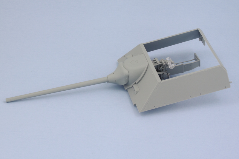
A quick test with the hull shows everything is lining up properly and the gun can be both elevated and traversed properly. This is useful not just for painting later on but also if you wanted to pose the gun with the travel lock engaged or traversed off to the side slightly for diorama purposes.

Next up will be tackling the casemate roof details and components.
Step 13 is a pretty simple step, it adds the interior plate to the front of the casemate along with the exhaust fan and the mount for the hull MG port. No gun is provided though, just the simple ball mount and tray for one is present. The little ball tray is numbered wrong in the instructions, it's actually C23 and not C22. Last but not least for this step is the addition of the clear periscopes for the driver.
Step 14 is the moment of truth when the whole gun is installed along with the cast external mantlet components. This almost requires three hands to get it all together and still allow the gun to traverse slightly. You also have to avoid gluing the base of the mount, G29, to the gun itself and only glue it to the top part of the mount, G31. This sandwiches the gun in between the two halves and the real C22 large pin connects at the top completing the full assembly. This gets glued to the front plate of the casemate and supports the whole deal rather nicely once you get it all in place. The saukopf mantlet then slides over the barrel to complete things for the gun. I also added the armored conical port for the hull MG in the closed position and the welded armored cover for the driver's periscopes. Ironically this last detail makes it all but impossible to tell that there are clear periscopes behind it but we all know they are there from the previous step.
A quick test with the hull shows everything is lining up properly and the gun can be both elevated and traversed properly. This is useful not just for painting later on but also if you wanted to pose the gun with the travel lock engaged or traversed off to the side slightly for diorama purposes.
Next up will be tackling the casemate roof details and components.
-
Bill Plunk
- Posts: 1245
- Joined: Wed Sep 28, 2022 10:18 pm
WIP 06-01-2015
Got the last of the major construction steps done in the latest round of progress. Steps 15-17 in the instructions cover the casemate roof and all the various hatch-related details. Since there's no interior to speak of, I decided to close up all the hatches except for the small 'rabbit ears' scope hatch for the commander. The kit provides the option for that small hatch to have a separate hinge point which makes life a lot easier in many ways, so the hinge point was added and the hatch put off to the side for painting and later installation to avoid complications with the camo scheme application.
Since I had no need for the gun to be traversed, I opted for the one-piece sliding cover for the gunner's sight. The advantage of the gun being able to traverse is still helpful as it made sure I had the sight and the opening on the part all properly lined up. I also opted for the close-in-defense weapon to be installed on this vehicle and added the appropriate cover. Getting the cover to line up is a little tricky due to the fact that it doesn't have the locater pins like the standard blanked-off cover does, a side-effect of the 'extra' sprue that Dragon throws into the kit for this little feature. Last but not least, all the clear periscopes were installed and some enamel Silver applied to their back faces and the front faces masked with small amounts of blue tack before the covers were added. The roof plate was then glued down and allowed to sit. Once it was set and no longer subject to flexing, the casemate was permanently joined to the lower hull courtesy of finger pressure and some strategic rubber bands.
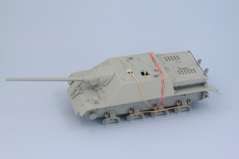
After that had set overnight, the last remaining details from Steps 18 and 19 were added in the form of the side skirt hangers and the antenna base. For the antenna, I clipped off the rod portion and drilled out the base with a #76 finger drill so it can take a brass 2m antenna later on. Since I had added the engine deck already to the hull, the rearmost pair of hangers needed the small tabs at the top that match up with the slots on the engine air intakes clipped off so that they could fit into the locater holes in the fenders correctly. The little fastback wing plates were also added and also needed a small modification to fit correctly. The molded on bracket designed to meet up with the rear rectangular support isn't the right size to match up correctly so all but the top part of the molded support outline on the plate was trimmed back so it would sit properly with the other two points.
I'm still waiting for my disc camo stencils to come in the mail that I ordered from the Uschi site, so in the meantime I'll be working on the tracks and the tools and such before starting the major paintwork.
Since I had no need for the gun to be traversed, I opted for the one-piece sliding cover for the gunner's sight. The advantage of the gun being able to traverse is still helpful as it made sure I had the sight and the opening on the part all properly lined up. I also opted for the close-in-defense weapon to be installed on this vehicle and added the appropriate cover. Getting the cover to line up is a little tricky due to the fact that it doesn't have the locater pins like the standard blanked-off cover does, a side-effect of the 'extra' sprue that Dragon throws into the kit for this little feature. Last but not least, all the clear periscopes were installed and some enamel Silver applied to their back faces and the front faces masked with small amounts of blue tack before the covers were added. The roof plate was then glued down and allowed to sit. Once it was set and no longer subject to flexing, the casemate was permanently joined to the lower hull courtesy of finger pressure and some strategic rubber bands.
After that had set overnight, the last remaining details from Steps 18 and 19 were added in the form of the side skirt hangers and the antenna base. For the antenna, I clipped off the rod portion and drilled out the base with a #76 finger drill so it can take a brass 2m antenna later on. Since I had added the engine deck already to the hull, the rearmost pair of hangers needed the small tabs at the top that match up with the slots on the engine air intakes clipped off so that they could fit into the locater holes in the fenders correctly. The little fastback wing plates were also added and also needed a small modification to fit correctly. The molded on bracket designed to meet up with the rear rectangular support isn't the right size to match up correctly so all but the top part of the molded support outline on the plate was trimmed back so it would sit properly with the other two points.
I'm still waiting for my disc camo stencils to come in the mail that I ordered from the Uschi site, so in the meantime I'll be working on the tracks and the tools and such before starting the major paintwork.
-
Bill Plunk
- Posts: 1245
- Joined: Wed Sep 28, 2022 10:18 pm
WIP 06-04-2015
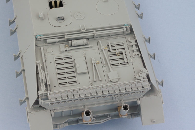
Since the rear engine deck is really the only available place for stuff, it's a busy place as all the tools and such that would be on the fenders got placed wherever there was an empty spot! I spent some time getting all the tools cleaned up and prepped for painting. Due to all the tight spaces, I decided not to fully replace the tool clamps but instead removed the relatively thick handles and replaced them with PE handles from a generic Griffon tool clamps PE set.
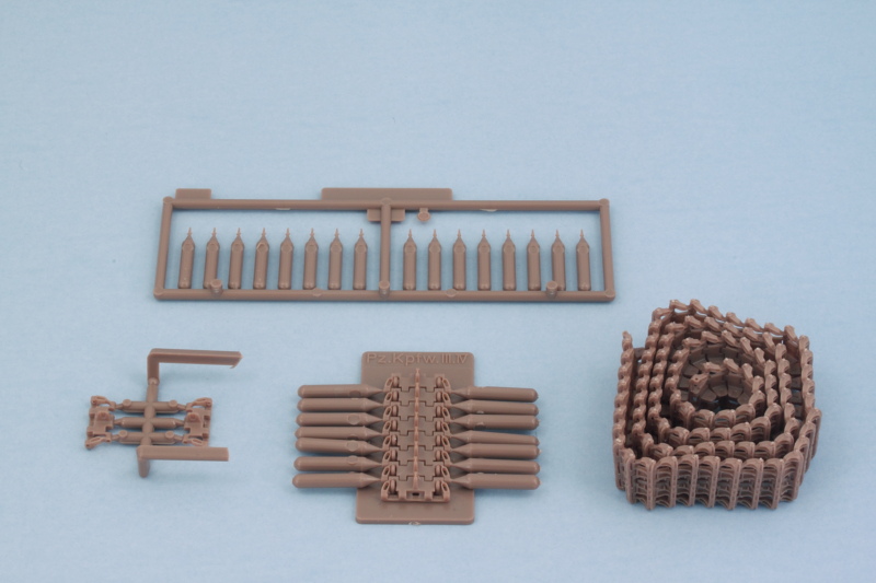
I also took advantage of the Magic Tracks in the kit to provide the 17-link spare track run. The instructions don't provide any guidance here and since the MK track set only has 8 spare links available, I cleaned up 20 links and did a test first to see how many would fit before settling on the 17 link arrangement. For no particular reason, I chose the links from the light grey bag and drilled out the pin holes on the one end and added the missing exposed pin on the other using short lengths of 0.5mm white styrene rod. Some quick work with a sanding stick removed the raised ejector marks on either side of the guide horns. Small amounts of Testors regular glue was used to assemble the run to ensure adequate work time to place and shape it properly in the mount without risking it becoming stuck to the rear hull or holder in the process.
The jack is the only tool that has the potential for interacting with the spare track run, so it has to be factored into the equation as well. The spare wheel holder parts were left off for now to make life easier in terms of painting the engine deck and including it in the camo pattern. Everything is dry fit at this point and playing nice with each other, always a plus!
-
Bill Plunk
- Posts: 1245
- Joined: Wed Sep 28, 2022 10:18 pm
WIP 06-15-2015
I've been working away in small chunks of time here and there on the MK workable tracks and managed to get both of the runs done without it being too tedious of a task. The MK tracks have three sprue attachment points that have to be cleaned up and then the links pinned together in 8-link sections with the supplied jig helping things out. The Dragon instructions indicate 97 links are needed per side but that seems low...even with only 3 vs. 4 return rollers the 'normal' Pz IV-family of vehicles typically take 98-100 links depending. I always assemble my runs a little short regardless and add the final links needed after the suspension is mounted to allow for slight differences and tension settings, so I stopped at 96 links just to be on the safe side.
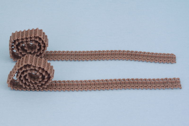
Total assembly time for the two runs together is roughly 4 hours but worth it to get the workable advantages for both painting/weathering and installation in my view.
Total assembly time for the two runs together is roughly 4 hours but worth it to get the workable advantages for both painting/weathering and installation in my view.
-
Bill Plunk
- Posts: 1245
- Joined: Wed Sep 28, 2022 10:18 pm
WIP 06-30-2015
A variety of things had sidelined this build a bit including my main airbrush deciding to give up the ghost and refuse to maintain air pressure internally. So it got shipped off for repair/replacement and a backup secured for the interim in order to get this build back on track.
So first order of business was laying down a primer coat. I used Testors MM enamel Italian Dark Brown to ensure there wouldn't be any unpainted plastic areas in the nooks and crannies and to check seams and such. This will get a chance to cure and then it's on to getting the camo scheme broad pattern sections laid down.
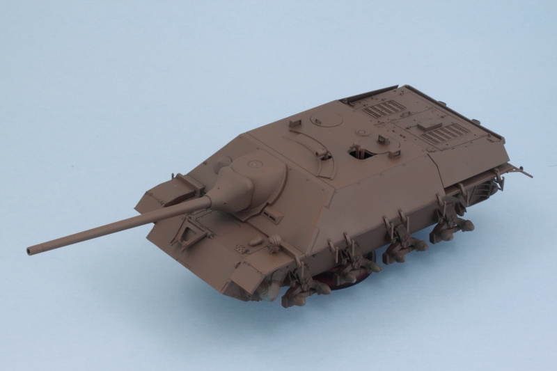
So first order of business was laying down a primer coat. I used Testors MM enamel Italian Dark Brown to ensure there wouldn't be any unpainted plastic areas in the nooks and crannies and to check seams and such. This will get a chance to cure and then it's on to getting the camo scheme broad pattern sections laid down.