Trumpeter KV-1 Pzkpfw 756(r) (2011)
-
Bill Plunk
- Posts: 1245
- Joined: Wed Sep 28, 2022 10:18 pm
Trumpeter KV-1 Pzkpfw 756(r) (2011)
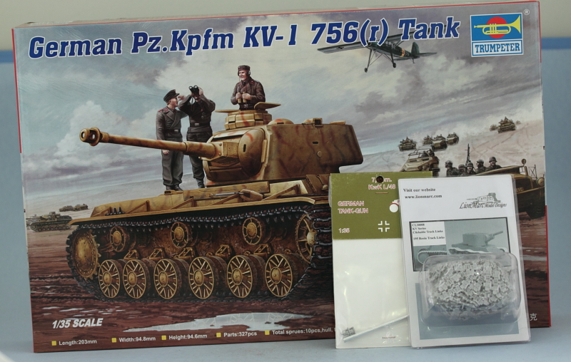
Build log for Trumpeter kit #366, German Pzkpfw 756(r) KV-1 with Lion Marc clickable resin tracks and a Jordi Rubio replacement aluminum barrel.
-
Bill Plunk
- Posts: 1245
- Joined: Wed Sep 28, 2022 10:18 pm
WIP 08-29-2011
I have a full week off from work this week for the Labor Day holiday and decided to take full advantage of it and started a simple project I've had in the stash for a while. The Trumpeter KV-1 kits don't have a lot of parts, the box top claims only 327 pieces, and I'm not adding much AM to speak of. I've had a set of click-together resin tracks sitting around so those will be pressed into service along with a surplus Jordi Rubio barrel, otherwise a straight OOB effort.
Step 1 is simple, it just calls for various holes/openings to be created in the hull side plates, fenders, and hull front/roof/glacis. The round holes are easy enough to open up with a drill bit but the rectangular ones take a little more care.
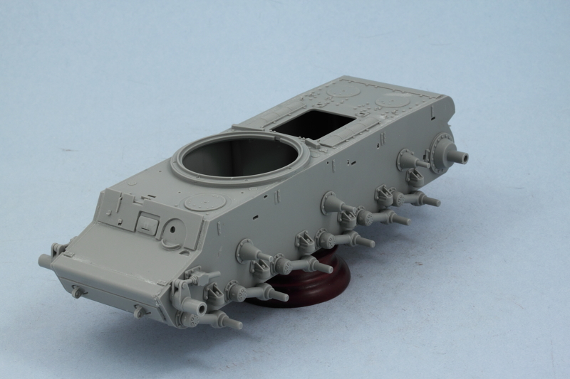
Step 2 starts the hull assembly, adding the side plates to the hull tub along with the rear hull plate. The rear plate includes the engine air exhaust vent screen and the deflector, it's important to get the vent screen at just the right angle so it will match up with the curved top rear hull plate that is added in Step 4, easily done by using part Q5 as a guide before the glue sets. I left off the clear brake light lens, that will get added after the hull is painted. The suspension arm bump stops are also added at this point to complete the step.
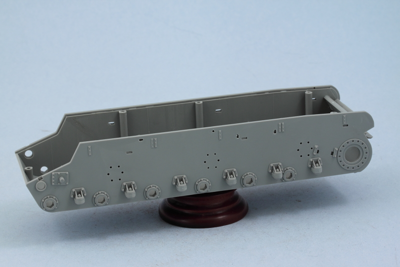
Step 3 continues the hull assembly, adding the hull top rear and front/glacis plates. I used a combination of regular and liquid glue and lots of strategic finger pressure to get a good join all along the hull edges before moving on. The step also adds the return roller mounts and the front tow eyes.
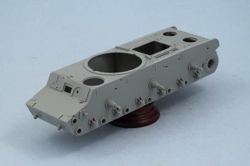
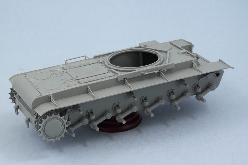
Step 4 continues the work on the suspension assembly, with 6 swing arms added per side. The swing arms had some flash and mold seams to deal with but are designed with a "hex" shape to insure they all align properly and sit level, a nice plus. The drive sprocket and idler mounts are also added in this step, neither of which are movable so it's a little bit of a mystery as to why Trumpeter urges you not to use any glue on the tension rod for the idler mount...once in position on the hull it's rock solid and un-movable with or without glue. The step also installs the curved rear hull plate and this required a lot of finger pressure to get a good join at the sides. Last but not least, the rear tow eyes were added along with the turret ring base to complete the step.
That's as far as I got today, more progress hopefully tomorrow!
Step 1 is simple, it just calls for various holes/openings to be created in the hull side plates, fenders, and hull front/roof/glacis. The round holes are easy enough to open up with a drill bit but the rectangular ones take a little more care.
Step 2 starts the hull assembly, adding the side plates to the hull tub along with the rear hull plate. The rear plate includes the engine air exhaust vent screen and the deflector, it's important to get the vent screen at just the right angle so it will match up with the curved top rear hull plate that is added in Step 4, easily done by using part Q5 as a guide before the glue sets. I left off the clear brake light lens, that will get added after the hull is painted. The suspension arm bump stops are also added at this point to complete the step.
Step 3 continues the hull assembly, adding the hull top rear and front/glacis plates. I used a combination of regular and liquid glue and lots of strategic finger pressure to get a good join all along the hull edges before moving on. The step also adds the return roller mounts and the front tow eyes.
Step 4 continues the work on the suspension assembly, with 6 swing arms added per side. The swing arms had some flash and mold seams to deal with but are designed with a "hex" shape to insure they all align properly and sit level, a nice plus. The drive sprocket and idler mounts are also added in this step, neither of which are movable so it's a little bit of a mystery as to why Trumpeter urges you not to use any glue on the tension rod for the idler mount...once in position on the hull it's rock solid and un-movable with or without glue. The step also installs the curved rear hull plate and this required a lot of finger pressure to get a good join at the sides. Last but not least, the rear tow eyes were added along with the turret ring base to complete the step.
That's as far as I got today, more progress hopefully tomorrow!
-
Bill Plunk
- Posts: 1245
- Joined: Wed Sep 28, 2022 10:18 pm
WIP 08-30-2011
Day 2 Progress:
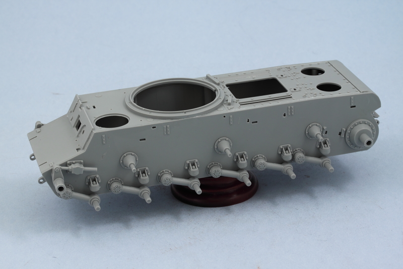
Work continued on the hull and suspension components with Step 5. This step adds the add-on nose armor (and I went ahead and added the lower hull plate as well called for in Step 10 as there's no reason to wait), the driver's armored visor and roof access hatch, the intake screens and rear engine hatches. I did have to use a small amount of Squadron White putty where the slot tabs on the nose armor plate install into the glacis as just the tiniest portion of the top of the slots was still visible.
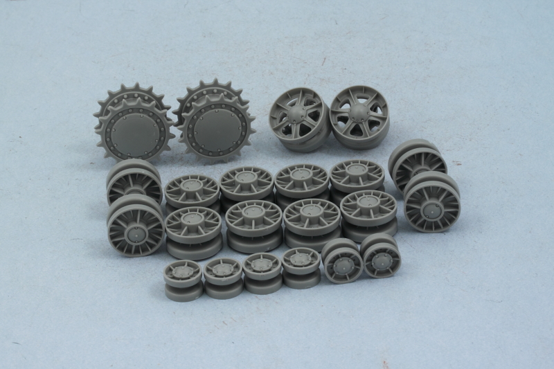
Step 6 assembles the road wheels, drive sprockets, and the hull MG mount. The road wheel assembly includes a poly cap and these had some flash that had to be cleaned up carefully to insure they would fit correctly inside the wheel halves. All 12 wheels were assembled along with the idlers, return rollers, and sprockets. I tested the fit all of the different wheels on their mounts and the only ones that had problems were the idlers. The diameter on the mount arm is slightly larger than the opening on the inner half of the idler wheel...of course, I found this out after I had assembled them which made the task that much harder to solve. I increased the diameter by carefully trimming some away with a sharp #11 blade and that helped but the fit was still so tight that when I tried to remove it from the mount, the tension "arm" snapped in two. That actually was a blessing in disguise as I hadn't glued the base of the idler mount down yet...so now I could work with it off the vehicle and it created a "tension-able" idler that I didn't have before. I went ahead and cut away the other undamaged mount on the other side to match...once the idlers are installed along with the fenders, the damage is hidden away so not a big deal. Care is needed when assembling the return rollers, there aren't any locater pins provided so you have to be very cure they aligned just right so they will fit properly on the mount pins.
Step 7 deals with the assembly of either the link-and-length or vinyl one-piece track options and doesn't apply for my build so was skipped entirely.
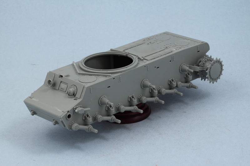
Steps 8 and 9 call for the installation of the road wheels to the hull, that will be done later after painting to make it easier to detail and weather them independently. The hull received more details in the form of the front headlight, the driver's periscope cover, the turret ring shot deflector, and the large rear engine access hatch. The sprockets were added but not glued down to allow them to rotate freely. Due to the way they fit along with the mud scrapers (parts A5/6), they have to go in place now vs later. Otherwise they too would have been left off for easier detail painting.
Next up are the fenders and their details.
Work continued on the hull and suspension components with Step 5. This step adds the add-on nose armor (and I went ahead and added the lower hull plate as well called for in Step 10 as there's no reason to wait), the driver's armored visor and roof access hatch, the intake screens and rear engine hatches. I did have to use a small amount of Squadron White putty where the slot tabs on the nose armor plate install into the glacis as just the tiniest portion of the top of the slots was still visible.
Step 6 assembles the road wheels, drive sprockets, and the hull MG mount. The road wheel assembly includes a poly cap and these had some flash that had to be cleaned up carefully to insure they would fit correctly inside the wheel halves. All 12 wheels were assembled along with the idlers, return rollers, and sprockets. I tested the fit all of the different wheels on their mounts and the only ones that had problems were the idlers. The diameter on the mount arm is slightly larger than the opening on the inner half of the idler wheel...of course, I found this out after I had assembled them which made the task that much harder to solve. I increased the diameter by carefully trimming some away with a sharp #11 blade and that helped but the fit was still so tight that when I tried to remove it from the mount, the tension "arm" snapped in two. That actually was a blessing in disguise as I hadn't glued the base of the idler mount down yet...so now I could work with it off the vehicle and it created a "tension-able" idler that I didn't have before. I went ahead and cut away the other undamaged mount on the other side to match...once the idlers are installed along with the fenders, the damage is hidden away so not a big deal. Care is needed when assembling the return rollers, there aren't any locater pins provided so you have to be very cure they aligned just right so they will fit properly on the mount pins.
Step 7 deals with the assembly of either the link-and-length or vinyl one-piece track options and doesn't apply for my build so was skipped entirely.
Steps 8 and 9 call for the installation of the road wheels to the hull, that will be done later after painting to make it easier to detail and weather them independently. The hull received more details in the form of the front headlight, the driver's periscope cover, the turret ring shot deflector, and the large rear engine access hatch. The sprockets were added but not glued down to allow them to rotate freely. Due to the way they fit along with the mud scrapers (parts A5/6), they have to go in place now vs later. Otherwise they too would have been left off for easier detail painting.
Next up are the fenders and their details.
-
Bill Plunk
- Posts: 1245
- Joined: Wed Sep 28, 2022 10:18 pm
WIP 08-31-2011
Day 3 Progress:
Focus today was on the fenders. These are covered in Steps 11-13 depending on the side in question and their respective details.
I started with the left side fender first as it had the most work to be done on it. I immediately encountered a small problem in that the tab slots in the hull sides aren't the same size as the mount tabs on the fender itself...so each of the three tabs had to be trimmed slightly to fit correctly. Same thing for the small tab at the front that matches up with the glacis plate. Some of the fender supports needed a small amount of putty help in order to butt properly against the hull and there were two open mount holes that aren't used on this particular KV-1, so those were filled with putty and sanded smooth. Once the fender was installed and set up, I added the side turret ring add-on armor. The cutouts at the bottom had to be enlarged slightly in order to fit correctly over the fender braces, easily done with a sharp #11 blade and some careful trimming.
I also added the jerry can rack at this stage but left off the cans themselves for easier painting and install later on. They are all "Wasser" cans so will need special markings/treatment to reflect that. The storage box was added as well to round out this fender. The spare track links for the rear portion will get added later after the hull is painted.
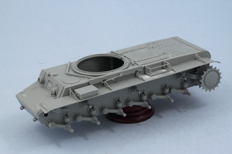
The right side fender was simpler in that it had no gear to install. The tabs here also needed some trimming and I also had to enlarge some of the openings for the fender braces on this side, something I didn't have to do on the left.
Step 14 constructs the tow cables and I skipped that for now and will come back to it later.
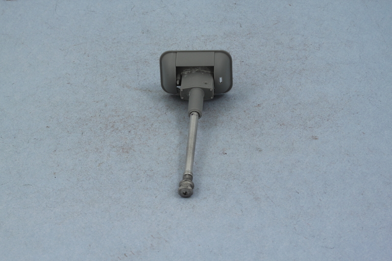
Step 15 begins work on the turret by focusing on the main gun. The step involves assembling the standard Pz IV mantlet and recoil housing and since I'm replacing the kit barrel with the JR barrel, I had some work to do here. First up I had to clean up the white metal muzzle brake and remove some casting flash with a sharp #11 blade and also file down some rough edges using round and square needle files to get it presentable. The muzzle brake was added to the aluminum barrel with CA gel.
In order to get the barrel mated up with the kit parts, I had to hollow out the recoil housing sleeve and remove one of the locater pins entirely. The barrel fit relatively snugly and only a small amount of CA was needed to secure it in place. I drilled out the coaxial MG with a #76 finger drill and installed it along with the main gun to the Pz IV mantlet with liquid glue. The Pz IV mantlet and gun were then installed into the KV-1 mantlet to round out the step. The mount pins have enough tension to support the weight of the JR barrel, so the elevation remains adjustable as a result.
Next up will be work on the rest of the turret.
Focus today was on the fenders. These are covered in Steps 11-13 depending on the side in question and their respective details.
I started with the left side fender first as it had the most work to be done on it. I immediately encountered a small problem in that the tab slots in the hull sides aren't the same size as the mount tabs on the fender itself...so each of the three tabs had to be trimmed slightly to fit correctly. Same thing for the small tab at the front that matches up with the glacis plate. Some of the fender supports needed a small amount of putty help in order to butt properly against the hull and there were two open mount holes that aren't used on this particular KV-1, so those were filled with putty and sanded smooth. Once the fender was installed and set up, I added the side turret ring add-on armor. The cutouts at the bottom had to be enlarged slightly in order to fit correctly over the fender braces, easily done with a sharp #11 blade and some careful trimming.
I also added the jerry can rack at this stage but left off the cans themselves for easier painting and install later on. They are all "Wasser" cans so will need special markings/treatment to reflect that. The storage box was added as well to round out this fender. The spare track links for the rear portion will get added later after the hull is painted.
The right side fender was simpler in that it had no gear to install. The tabs here also needed some trimming and I also had to enlarge some of the openings for the fender braces on this side, something I didn't have to do on the left.
Step 14 constructs the tow cables and I skipped that for now and will come back to it later.
Step 15 begins work on the turret by focusing on the main gun. The step involves assembling the standard Pz IV mantlet and recoil housing and since I'm replacing the kit barrel with the JR barrel, I had some work to do here. First up I had to clean up the white metal muzzle brake and remove some casting flash with a sharp #11 blade and also file down some rough edges using round and square needle files to get it presentable. The muzzle brake was added to the aluminum barrel with CA gel.
In order to get the barrel mated up with the kit parts, I had to hollow out the recoil housing sleeve and remove one of the locater pins entirely. The barrel fit relatively snugly and only a small amount of CA was needed to secure it in place. I drilled out the coaxial MG with a #76 finger drill and installed it along with the main gun to the Pz IV mantlet with liquid glue. The Pz IV mantlet and gun were then installed into the KV-1 mantlet to round out the step. The mount pins have enough tension to support the weight of the JR barrel, so the elevation remains adjustable as a result.
Next up will be work on the rest of the turret.
-
Bill Plunk
- Posts: 1245
- Joined: Wed Sep 28, 2022 10:18 pm
WIP 09-01-2011
Day 4 Progress:
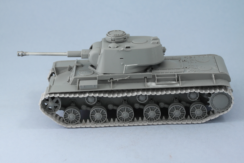
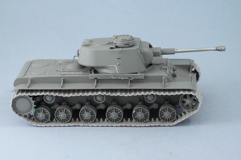
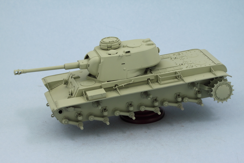
Construction completed today with the remaining outstanding items being the turret and tracks.
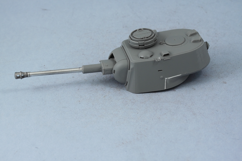
The turret assembly is covered in Step 16 and is broken up into 3 sub-assemblies. The first joins the upper and lower halves of the turret together and adds the turret roof details in the form of the armored vent cover and periscope guards. The rear turret MG is also installed along with the turret side grab-handles.
Since this particular KV-1 features a cast turret, the kit parts accurately recreate the casting line seen around the turret rear and extending down to the base of the turret ring. The angled area at the base of the turret ring needed some help to look right so I used narrow strips of masking tape and Squadron White putty to improve the detail in those areas. Once the putty dried, I carefully removed the masking tape and voil�! cast line detail added.
The other sub-assembly deals with the Pz IV type commander's cupola. Since I'm showing the hatches closed, there was no need to add the interior detail parts for the viewing slits and the cupola halves went together without issue, just a little care required to get everything lined up right. The normal KV-1 hatch was added as well to round out the step. The third sub-assembly would have added the one-piece styrene main gun barrel but I already took care of that with the JR replacement.
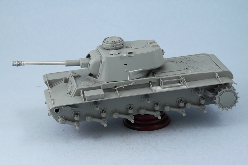
A simple test-fit to make sure the turret played nice with the hull:
Next came the tracks. The Lion Marc resin tracks are "click-able" so they assemble very easily. Some minor resin flash was present on the openings for the sprocket teeth on each link but that was easily removed as each link was added to the track run. Once assembled, the links are fully workable.
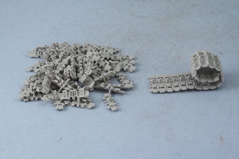
I dry-fitted the road wheels and return rollers and used a small amount of poster blue-tack putty to hold the idlers in position. Test fits with the track runs and adjustments with the idler showed that 87 links per side would give the look I wanted. Since the Lion Marc set provides 195 links, there's plenty of extras so it was possible to weed out the few I encountered that were poorly cast or had weak connector pins.
Now it's time to advance to the painting stage but that won't happen until the weekend as my wife has time off tomorrow as well and we are planning a day out together to take advantage!
Construction completed today with the remaining outstanding items being the turret and tracks.
The turret assembly is covered in Step 16 and is broken up into 3 sub-assemblies. The first joins the upper and lower halves of the turret together and adds the turret roof details in the form of the armored vent cover and periscope guards. The rear turret MG is also installed along with the turret side grab-handles.
Since this particular KV-1 features a cast turret, the kit parts accurately recreate the casting line seen around the turret rear and extending down to the base of the turret ring. The angled area at the base of the turret ring needed some help to look right so I used narrow strips of masking tape and Squadron White putty to improve the detail in those areas. Once the putty dried, I carefully removed the masking tape and voil�! cast line detail added.
The other sub-assembly deals with the Pz IV type commander's cupola. Since I'm showing the hatches closed, there was no need to add the interior detail parts for the viewing slits and the cupola halves went together without issue, just a little care required to get everything lined up right. The normal KV-1 hatch was added as well to round out the step. The third sub-assembly would have added the one-piece styrene main gun barrel but I already took care of that with the JR replacement.
A simple test-fit to make sure the turret played nice with the hull:
Next came the tracks. The Lion Marc resin tracks are "click-able" so they assemble very easily. Some minor resin flash was present on the openings for the sprocket teeth on each link but that was easily removed as each link was added to the track run. Once assembled, the links are fully workable.
I dry-fitted the road wheels and return rollers and used a small amount of poster blue-tack putty to hold the idlers in position. Test fits with the track runs and adjustments with the idler showed that 87 links per side would give the look I wanted. Since the Lion Marc set provides 195 links, there's plenty of extras so it was possible to weed out the few I encountered that were poorly cast or had weak connector pins.
Now it's time to advance to the painting stage but that won't happen until the weekend as my wife has time off tomorrow as well and we are planning a day out together to take advantage!
-
Bill Plunk
- Posts: 1245
- Joined: Wed Sep 28, 2022 10:18 pm
WIP 09-04-2011
Day 5 & 6 Progress:
Spent the weekend working with the airbrush to get the paint scheme done. First order of business was the application of a primer coat of Testors Model Master enamel Italian Dark Brown. This allowed me to check all the various putty work here and there as well as some of the join seams to make sure everything was set.
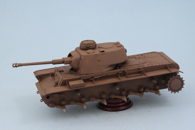
Next came the base coat of 50/50 MM enamel Light Gray/Panzer Dunkelgelb.
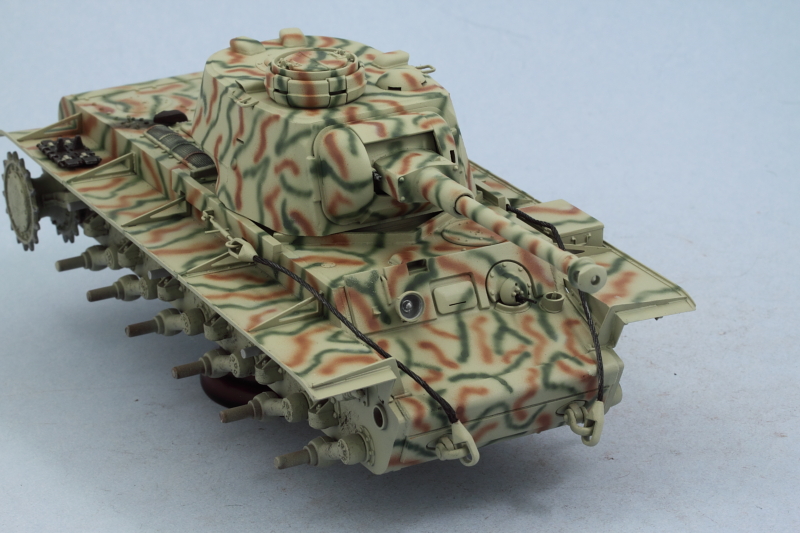
I let that set overnight as it took quite a bit of time to get to that stage and my airbrush trigger finger needed a rest! The camo pattern was next. The kit guide and box top aren't much help, so I decided to go with a worm/stripe pattern for the three tone field-applied scheme. I started with the rot-braun first using a 50/50 mix of MM enamel Military Brown/Leather.
The oliv-grun portions came next using MM enamel Khaki.
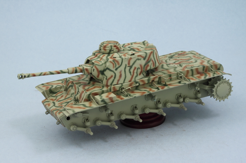
After some clean-up and fine-tuning with the original base coat colors, I thinned what I had left in the paint cut to a wash consistency and them applied a mist coat from roughly 12 inches to tie the scheme together.
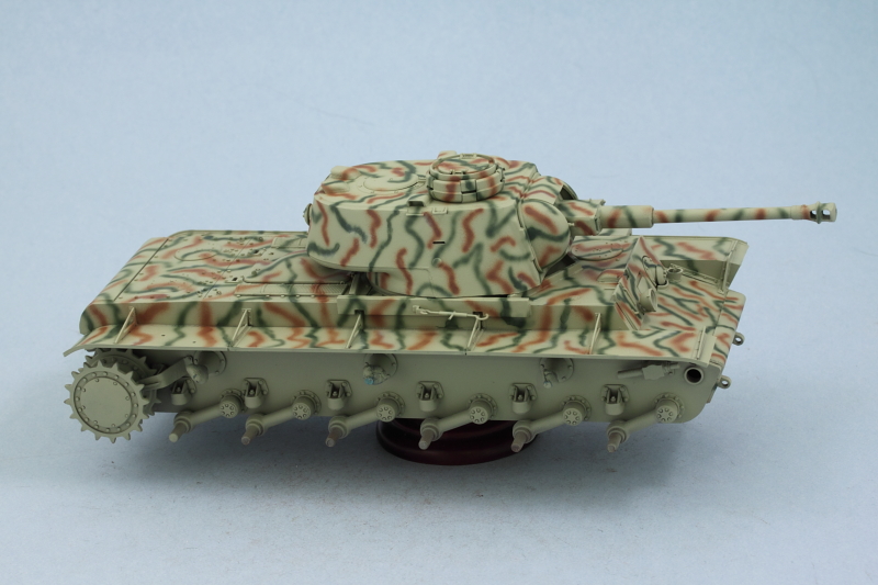
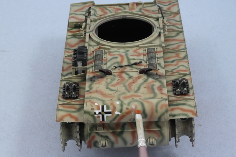
Just to give an idea of how the pattern looks like from overhead, here's a shot from the rear.
Tomorrow I'll start work on the tracks and other details.
Spent the weekend working with the airbrush to get the paint scheme done. First order of business was the application of a primer coat of Testors Model Master enamel Italian Dark Brown. This allowed me to check all the various putty work here and there as well as some of the join seams to make sure everything was set.
Next came the base coat of 50/50 MM enamel Light Gray/Panzer Dunkelgelb.
I let that set overnight as it took quite a bit of time to get to that stage and my airbrush trigger finger needed a rest! The camo pattern was next. The kit guide and box top aren't much help, so I decided to go with a worm/stripe pattern for the three tone field-applied scheme. I started with the rot-braun first using a 50/50 mix of MM enamel Military Brown/Leather.
The oliv-grun portions came next using MM enamel Khaki.
After some clean-up and fine-tuning with the original base coat colors, I thinned what I had left in the paint cut to a wash consistency and them applied a mist coat from roughly 12 inches to tie the scheme together.
Just to give an idea of how the pattern looks like from overhead, here's a shot from the rear.
Tomorrow I'll start work on the tracks and other details.
-
Bill Plunk
- Posts: 1245
- Joined: Wed Sep 28, 2022 10:18 pm
WIP 09-10-2011
Lots of progress to report in the details department.
First up is the rear hull. The spare track links were done first, using my normal MM Metalizer Non-buffing Gunmetal base followed by a light wash of enamel Rust. A very light dry-brushing of enamel Steel was followed by some dry-brushed Burnt Umber and the links were installed into position on the fenders.
For the exhausts, they also were done with a metalizer Gunmetal base-coat but given 3 applications of the Rust wash (spaced out of course to allow the previous coats to dry thoroughly). I used some black artist pastels to darken their mouths and also put down some soot accumulation on the hull surface. This will get toned down and blended in a bit in later weathering stages.
Most challenging of all were the engine air intakes. Since these are molded as one-piece by Trumpeter and I didn't want to spend for AM PE/grills...I resorted to using optical tricks. First I applied a wash of thinned enamel Gunmetal with a small detail brush and let it dry. A 2nd wash application followed where needed to darken the "squares" in the mesh. Using the same small detail brush, I very carefully dry-brushed the hull color where the camo stripes hadn't intersected to bring the mesh back out and create a 3-d result.
The lower hull was "pre-weathered" at this point using a round 0 sable brush and stippling some Burnt Umber to simulate scuffs/scrapes/wear. I suppose for 100% accuracy sake I could have done this with Russian Armor Green instead but the Burnt Umber just looks better in my opinion.
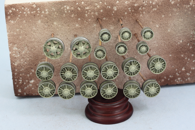
The road wheels, idlers, and return rollers also got some attention. I applied a Burnt Umber wash to the ribbed details on all the wheels and let it dry. By doing this now while they are still on the toothpicks, I got a more even finish than if I had done it when the wheels were installed. I also detailed all the bare metal surfaces using MM Non-buffing Metalizer Steel and then dry-brushing Burnt Umber over the metalizer coat.
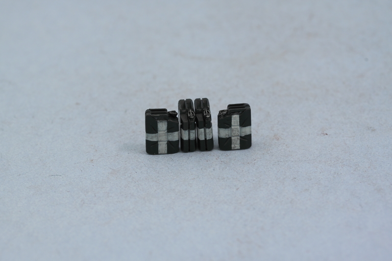
The 4 water cans for the left side were also detailed. I airbrushed a coat of Panzer Schwarzgrau and then used strips of masking tape for the water cross markings. Rather than use White (too stark), I used Light Gray instead and lightly dry-brushed some of the Panzer Schwarzgau to give it a slightly used look. The cans were then installed in their rack on the fender.
The front hull details were also taken care of. The kit supplies some very nice braided copper wire for the tow cables but you have to be careful as there's very little extra and the length of copper wire needed is 71mm per cable. I used CA gel to glue on the tow ends and then airbrushed the hull color and painted the cable portions with Metalizer Gunmetal and lightly dry-brushed with Steel. The cables aren't permanently secured to allow a little flexibility in the weathering process to work around them.
The headlight was detailed with Testors enamel Silver and the hull and turret MGs detailed as well to round things out.
Next up will be the decals and prep for the weathering to begin.
First up is the rear hull. The spare track links were done first, using my normal MM Metalizer Non-buffing Gunmetal base followed by a light wash of enamel Rust. A very light dry-brushing of enamel Steel was followed by some dry-brushed Burnt Umber and the links were installed into position on the fenders.
For the exhausts, they also were done with a metalizer Gunmetal base-coat but given 3 applications of the Rust wash (spaced out of course to allow the previous coats to dry thoroughly). I used some black artist pastels to darken their mouths and also put down some soot accumulation on the hull surface. This will get toned down and blended in a bit in later weathering stages.
Most challenging of all were the engine air intakes. Since these are molded as one-piece by Trumpeter and I didn't want to spend for AM PE/grills...I resorted to using optical tricks. First I applied a wash of thinned enamel Gunmetal with a small detail brush and let it dry. A 2nd wash application followed where needed to darken the "squares" in the mesh. Using the same small detail brush, I very carefully dry-brushed the hull color where the camo stripes hadn't intersected to bring the mesh back out and create a 3-d result.
The lower hull was "pre-weathered" at this point using a round 0 sable brush and stippling some Burnt Umber to simulate scuffs/scrapes/wear. I suppose for 100% accuracy sake I could have done this with Russian Armor Green instead but the Burnt Umber just looks better in my opinion.
The road wheels, idlers, and return rollers also got some attention. I applied a Burnt Umber wash to the ribbed details on all the wheels and let it dry. By doing this now while they are still on the toothpicks, I got a more even finish than if I had done it when the wheels were installed. I also detailed all the bare metal surfaces using MM Non-buffing Metalizer Steel and then dry-brushing Burnt Umber over the metalizer coat.
The 4 water cans for the left side were also detailed. I airbrushed a coat of Panzer Schwarzgrau and then used strips of masking tape for the water cross markings. Rather than use White (too stark), I used Light Gray instead and lightly dry-brushed some of the Panzer Schwarzgau to give it a slightly used look. The cans were then installed in their rack on the fender.
The front hull details were also taken care of. The kit supplies some very nice braided copper wire for the tow cables but you have to be careful as there's very little extra and the length of copper wire needed is 71mm per cable. I used CA gel to glue on the tow ends and then airbrushed the hull color and painted the cable portions with Metalizer Gunmetal and lightly dry-brushed with Steel. The cables aren't permanently secured to allow a little flexibility in the weathering process to work around them.
The headlight was detailed with Testors enamel Silver and the hull and turret MGs detailed as well to round things out.
Next up will be the decals and prep for the weathering to begin.
-
Bill Plunk
- Posts: 1245
- Joined: Wed Sep 28, 2022 10:18 pm
WIP 09-11-2011
NFL games being shown in my area weren't engaging enough so I spent some time at the bench instead.
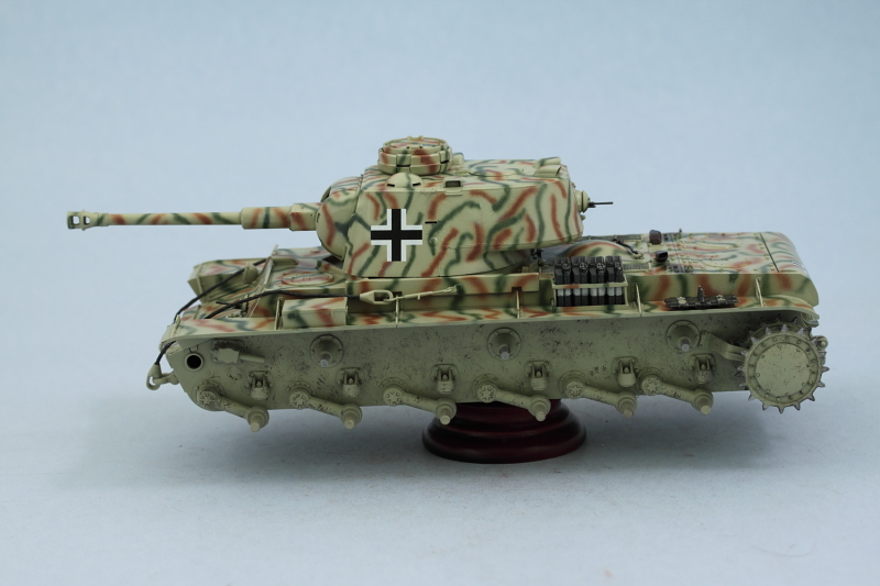
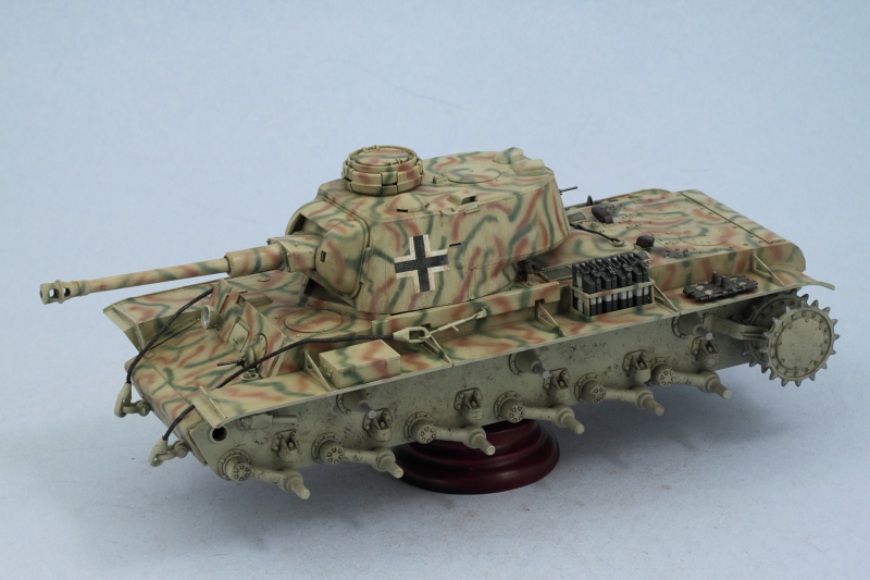
Applied a coat of Future via airbrush and let it set for about an hour before adding the decals. The Trumpeter markings set is very simple, 3 over-sized balkenkreuze are all that is called for. 2 for the turret and one for the hull rear. These were added and treated with Walther's Solvaset to insure they snugged down tight to the finish. Once they had set, I added a 2nd coat of Future to seal them in and protect against the coming weathering stages.
Should have this one done over the course of the next week or so depending on how things shake out.
-
Bill Plunk
- Posts: 1245
- Joined: Wed Sep 28, 2022 10:18 pm
WIP 09-15-2011
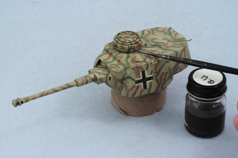
The weathering process has begun. First step was an application of an overall wash of thinned enamel MM Raw Umber using a round 0 sable brush.
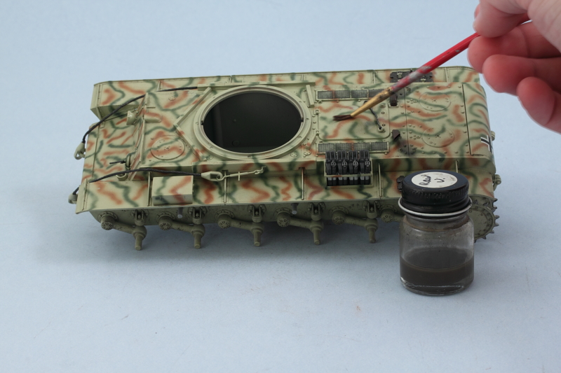
Dot filters came next. Using small dots (Flat White, Raw Sienna, Panzer Dunkelgelb) placed with a spotter brush, I blended the dots together using a very lightly thinner dampened square-tip brush. Work was done in small sections at a time and with frequent cleaning of the square brush until the entire vehicle was done.
Next came a pin wash of enamel MM Burnt Umber to bring out the details. The pin wash was applied using a pointed 10/0 brush. After the wash was dry, I came back with the same brush and clean thinner and removed any tide marks or excess wash where appropriate.
I noticed a couple of spots that needed adjustment after taking the photos and those were duly addressed. Now it's on to the pigment weathering for the lower hull and tracks.
-
Bill Plunk
- Posts: 1245
- Joined: Wed Sep 28, 2022 10:18 pm
Completion 09-18-2011
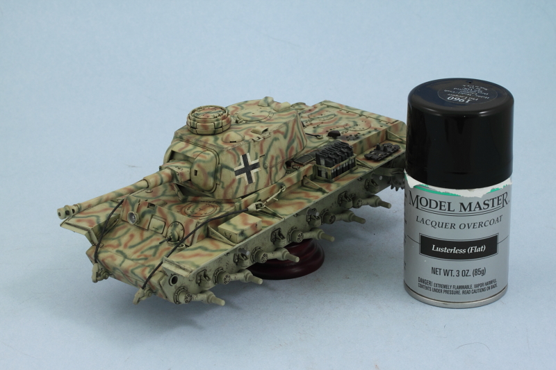
Work continued from where I left off previously with the weathering and the first order of business was to seal in all of the wash work and remove any remaining gloss effect from the Future coats. I applied an overall coat of Model Master Lusterless Flat lacquer via spray can. Fumes are powerful so this was done in the spray booth with the exhaust fans going full bore and while wearing a breather mask.
Now it was time for some pigment attention and I started with the lower hull. I used Mig Dark Mud pigment mixed with filtered water (with a drop of liquid dish-washing soap added to break the surface tension) and applied with an old brush.
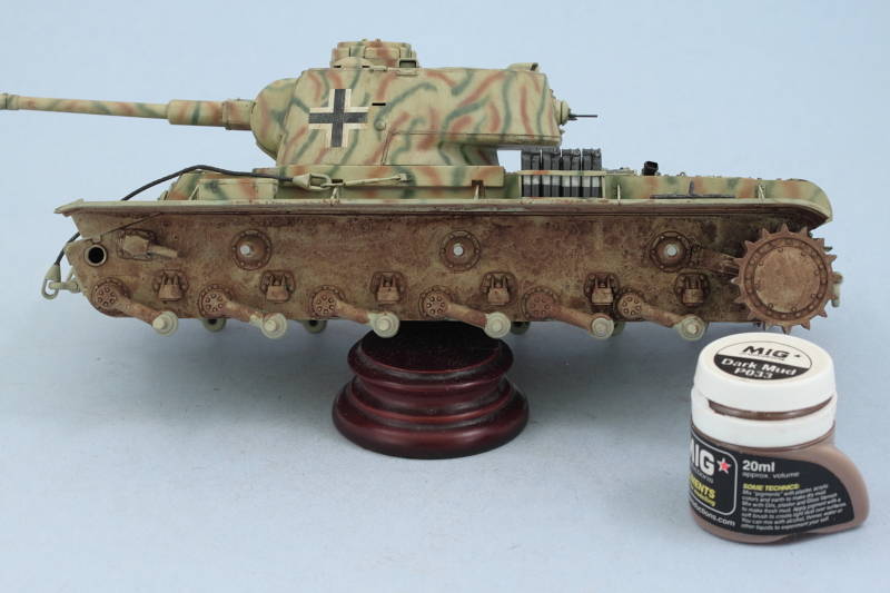
This was left to air dry (about 20 minutes), then attacked with a wet q-tip. The Dark Mud pigment behaves more like a "stain" vs the other pigments in the Mig line and that's the effect I was going for. This built on the previous weathering attention on the lower hull and I removed virtually all of the pigment but allowed a heavier build-up to remain around the suspension arms/hubs and bump stops.
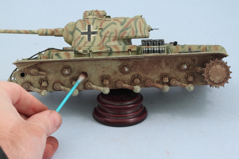
The road wheels, idlers, and return rollers were given a similar treatment off the vehicle to make it easier to work with them and get a more consistent result. Due to the numerous spokes on the road wheels, I had to work those small areas using a wooden toothpick instead of a q-tip, but otherwise the process was the same. The wheels were then installed into position on the hull.
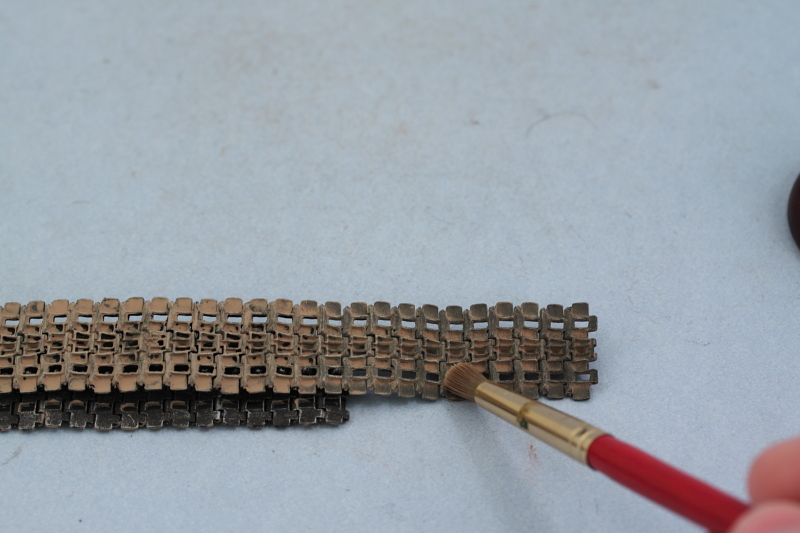
Then it was the tracks' turn. Since they are a darker starting color, I used Mig Dry Mud for them. Applied the wet mix and let it air dry. I used an old disposable contact lens container and worked each link individually (one of the beauties of using workable tracks IMHO).
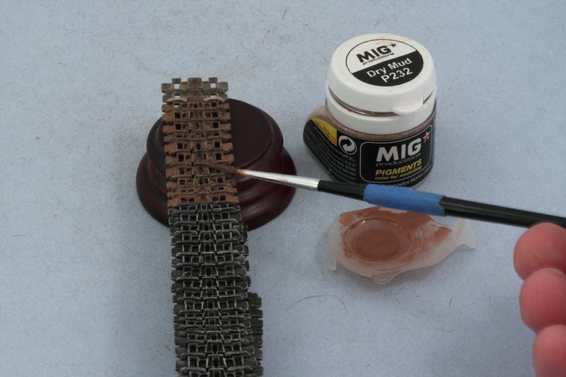
Using a combination of round and square stiff-bristled brushes, the excess pigment was removed until i had the look I wanted.
The tracks were then installed along with the idlers. The idlers were adjusted as needed before the glue set to allow for the right amount of sag on either side. I also installed the clear parts for the front headlight and rear brake light to complete the remaining little details.
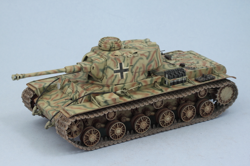
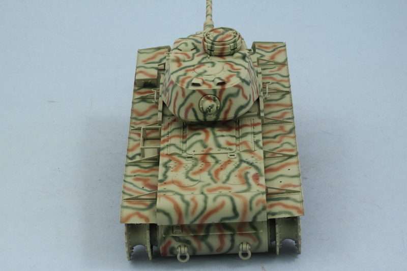
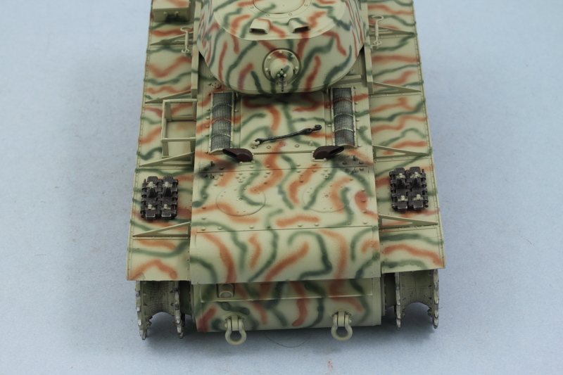
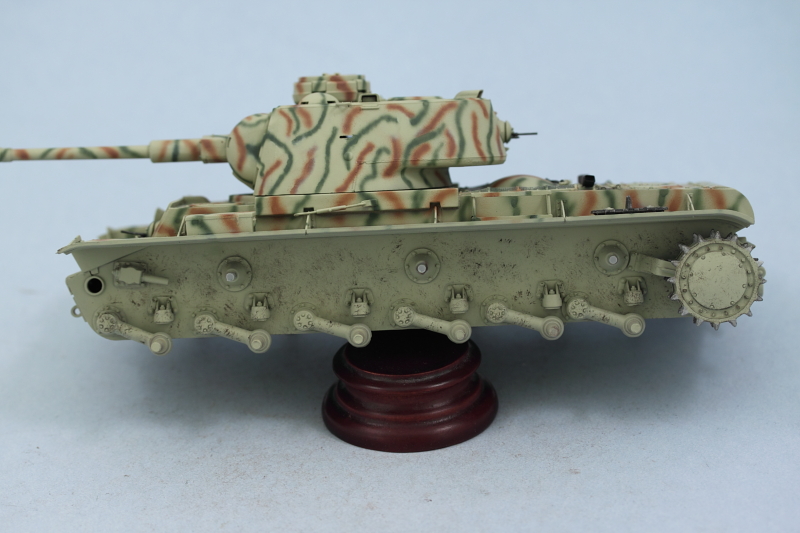
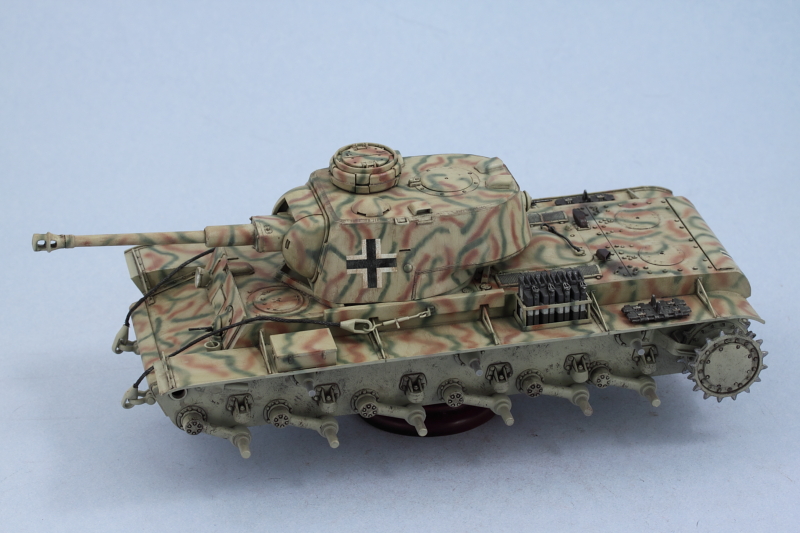
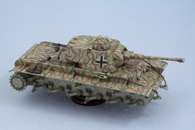
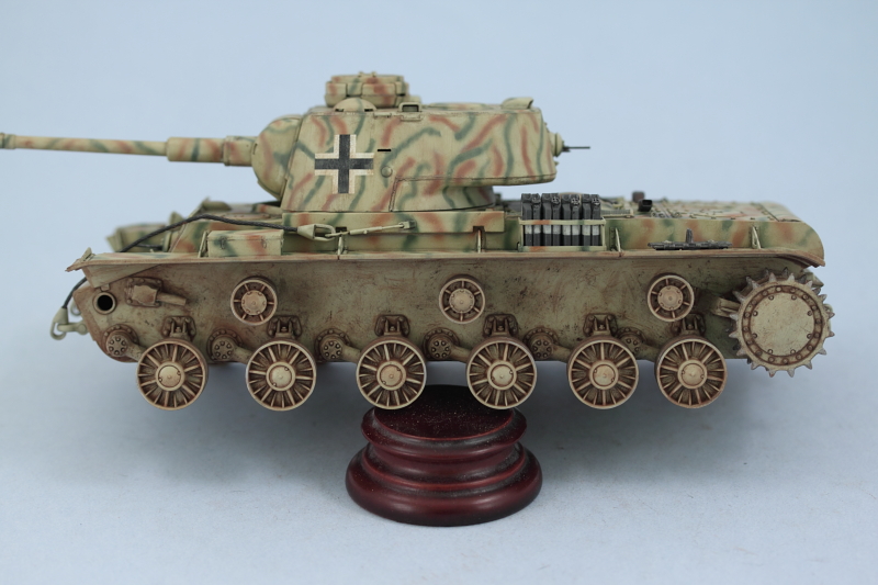
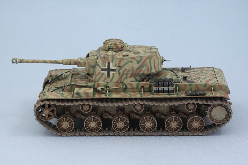
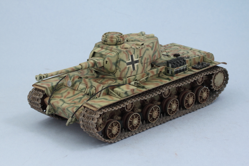
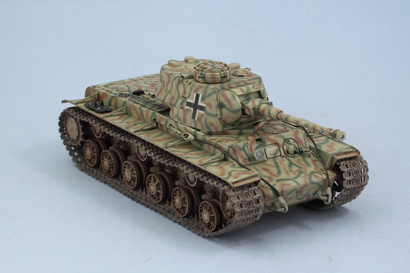
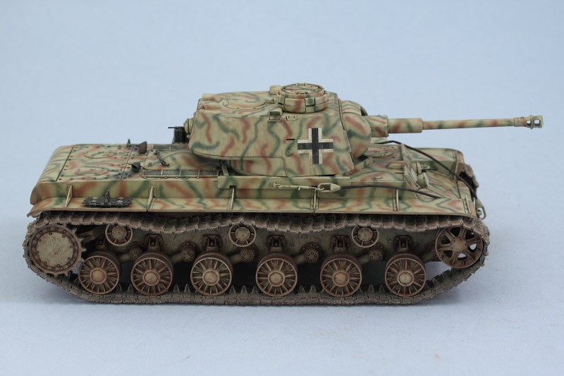
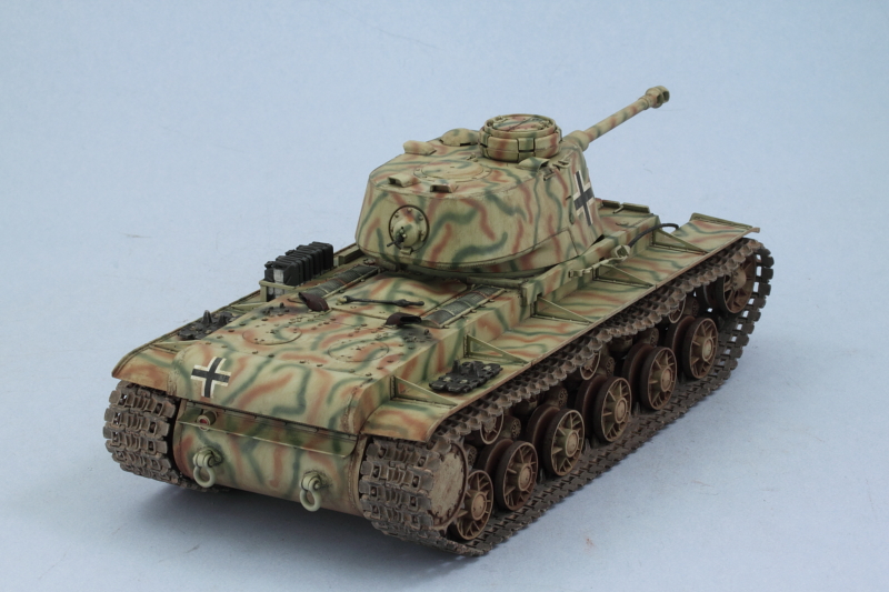
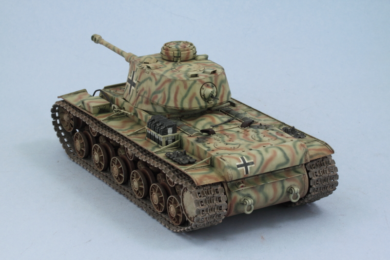
Then it was off to the photo booth for the finished walk-around shots.
Now it was time for some pigment attention and I started with the lower hull. I used Mig Dark Mud pigment mixed with filtered water (with a drop of liquid dish-washing soap added to break the surface tension) and applied with an old brush.
This was left to air dry (about 20 minutes), then attacked with a wet q-tip. The Dark Mud pigment behaves more like a "stain" vs the other pigments in the Mig line and that's the effect I was going for. This built on the previous weathering attention on the lower hull and I removed virtually all of the pigment but allowed a heavier build-up to remain around the suspension arms/hubs and bump stops.
The road wheels, idlers, and return rollers were given a similar treatment off the vehicle to make it easier to work with them and get a more consistent result. Due to the numerous spokes on the road wheels, I had to work those small areas using a wooden toothpick instead of a q-tip, but otherwise the process was the same. The wheels were then installed into position on the hull.
Then it was the tracks' turn. Since they are a darker starting color, I used Mig Dry Mud for them. Applied the wet mix and let it air dry. I used an old disposable contact lens container and worked each link individually (one of the beauties of using workable tracks IMHO).
Using a combination of round and square stiff-bristled brushes, the excess pigment was removed until i had the look I wanted.
The tracks were then installed along with the idlers. The idlers were adjusted as needed before the glue set to allow for the right amount of sag on either side. I also installed the clear parts for the front headlight and rear brake light to complete the remaining little details.
Then it was off to the photo booth for the finished walk-around shots.