
Dragon Pzkpfw III Ausf. H (5.0cm) Late Production (2020)
-
Bill Plunk
- Posts: 1245
- Joined: Wed Sep 28, 2022 10:18 pm
Dragon Pzkpfw III Ausf. H (5.0cm) Late Production (2020)
Build log for Dragon's kit #6642 Pzkpfw III Ausf H (5.0cm) Late Production using Model Kasten SK-24 workable tracks and Panzer Art RE35-014 resin replacement mantlet and gun barrel arrangement.
-
Bill Plunk
- Posts: 1245
- Joined: Wed Sep 28, 2022 10:18 pm
WIP 06-30-2019
This particular project will revisit some old familiar ground as almost all of the Pz 3 Hs ended up in North Africa. I have previously built a Pzkpfw III Ausf G using the old Dragon Imperial kit some years back and this kit, #6642, allows me to do something similar again but with a modern-quality kit to work from. One of the vehicles included in the marking set is Red 5 of the 18 PzRgt, 15 Pz Div, and it just so happens that there's also a pic of that particular vehicle in Trojca book on the Pz 3.
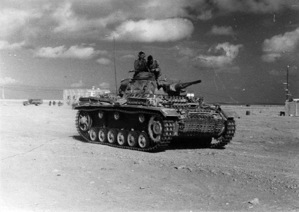
You can see the obvious appeal, it's got some nice field modifications in the form of spare tracks, water can racks on the fenders, and the addition of the canvas barrel cover, so should provide some fun 'extras' to play with!
As is the usual practice for Dragon kits, Step 1 starts with the road wheels, idlers, sprockets, and return rollers. Since I'm using workable replacement tracks, I always build a short run of 16 links to use as a gauge to ensure the gap arrangement will play nice with them later on in the build. The idler wheels include PE inserts on their inner rims, these were added using liquid glue to provide some flexibility with getting their placement just right before the idler halves were joined together.

With that taken care of, the roadwheels and return rollers got their turn. Each had their attachment points cleaned up and the mold seams removed using a 220-grit sanding stick. The return rollers were assembled while the roadwheel halves were left separate to allow for easier painting later on when that time comes.

The step also calls for the assembly of the idler wheel tension arms but I left that out for now until I'm ready to install them in Step 3 along with the other hull details that it integrates with so as to avoid any potential problems. This one is off and running!
You can see the obvious appeal, it's got some nice field modifications in the form of spare tracks, water can racks on the fenders, and the addition of the canvas barrel cover, so should provide some fun 'extras' to play with!
As is the usual practice for Dragon kits, Step 1 starts with the road wheels, idlers, sprockets, and return rollers. Since I'm using workable replacement tracks, I always build a short run of 16 links to use as a gauge to ensure the gap arrangement will play nice with them later on in the build. The idler wheels include PE inserts on their inner rims, these were added using liquid glue to provide some flexibility with getting their placement just right before the idler halves were joined together.
With that taken care of, the roadwheels and return rollers got their turn. Each had their attachment points cleaned up and the mold seams removed using a 220-grit sanding stick. The return rollers were assembled while the roadwheel halves were left separate to allow for easier painting later on when that time comes.
The step also calls for the assembly of the idler wheel tension arms but I left that out for now until I'm ready to install them in Step 3 along with the other hull details that it integrates with so as to avoid any potential problems. This one is off and running!
-
Bill Plunk
- Posts: 1245
- Joined: Wed Sep 28, 2022 10:18 pm
WIP 07-03-2019
Work continued on the lower hull components and suspension. Step 2 is a fairly simple step, it adds the bottom portions of the fender supports and the crew side escape hatches. The left side gets the modified "special" frame support for the first mount due to the need to have to clear the shock absorber that gets installed in the next step.

Step 3 is an involved step as it adds all of the suspension elements. Since Dragon re-used the hull from their previous early-Pz III variants, one of those components involves placing the first return roller mounts, part V21, into the correct revised postion closer to the drive sprocket for the Ausf H. There are two locator holes provided in the hull side (one gets filled in while the other is there to help place the part) but the parts themselves don't have pins to make use of them. I used some white styrene rod to create my own and drilled out the locator hole so that they could pass all the way through the hull side. For the unused hole, that was filled with the same white styrene rod and sanded smooth after the glue had dried.

The rest of the step adds in all the suspension arms, torsion rods, shock absorbers, and bump stops along with the bow plate base and front portions of the drive sprocket base. All of the parts are 'handed', so I worked on one side at a time to avoid accidentally installing things on the wrong hull side. The middle 4 swing arms can be made to be workable if you remove the mount pins they sit on but since I have no need for that, I left them static along with the fixed front and rear arms that connect up with the shock absorbers. I also added the drive sprocket housings that were included in Step 1 but left the sprockets themselves off for now.

Next up will be working on the rear hull plate and exhaust system.
Step 3 is an involved step as it adds all of the suspension elements. Since Dragon re-used the hull from their previous early-Pz III variants, one of those components involves placing the first return roller mounts, part V21, into the correct revised postion closer to the drive sprocket for the Ausf H. There are two locator holes provided in the hull side (one gets filled in while the other is there to help place the part) but the parts themselves don't have pins to make use of them. I used some white styrene rod to create my own and drilled out the locator hole so that they could pass all the way through the hull side. For the unused hole, that was filled with the same white styrene rod and sanded smooth after the glue had dried.
The rest of the step adds in all the suspension arms, torsion rods, shock absorbers, and bump stops along with the bow plate base and front portions of the drive sprocket base. All of the parts are 'handed', so I worked on one side at a time to avoid accidentally installing things on the wrong hull side. The middle 4 swing arms can be made to be workable if you remove the mount pins they sit on but since I have no need for that, I left them static along with the fixed front and rear arms that connect up with the shock absorbers. I also added the drive sprocket housings that were included in Step 1 but left the sprockets themselves off for now.
Next up will be working on the rear hull plate and exhaust system.
-
Bill Plunk
- Posts: 1245
- Joined: Wed Sep 28, 2022 10:18 pm
WIP 07-05-2019
Dealing with the rear hull plate and exhaust details turned out to be more complicated than it looked at first glance. Steps 4 and 6 deal with this in the instructions and after careful study of how all the parts needed to go together in reality vs. what the instructions called for, I did it a little different.
First up was prepping the actual rear plate components called out in Step 4. The base plate had its details removed and sanded smooth per the instructions so that the applique plate could be added on top of it. I also assembled the tow points so that they would play nice with the applique plate.
The applique plate was kept separate and the exhausts and crank starter cover installed in position. This was done after I had tried a test fit of the applique plate and realized that the designed cutouts weren't quite big enough to fit correctly around the tow points on the original rear base plate. They don't clear the final bolt on the tow point mounts equally and this presented a small challenge to correct. Since both openings had to be trimmed equally to avoid the exhausts getting off-center, I installed them where they needed to go and then fixed the openings by carefully enlarging them with the point of a #11 blade and checking the fit until it would drop into place as originally intended. I also deepened the exhaust pipes by drilling them out with a drill bit/pin vise to improve their look.

In Step 6, there's a little pop-up box that deals with the upper parts of the rear hull that include the air vent and the angled armored plate that covers it. The assembly order that the instructions call for is a little bizarre and very awkward. It calls for it all to be attached together as a single assembly first and then installed into the hull as a single module. I found it much easier to keep the components separate and take advantage of the hull plate and rear frame as additional alignment guides. More on that a little later on. There's also a second box for the option of the type of smoke grenade box between an early and later version. Since this is a late production H, I opted for the later armored version. It was also assembled but left separate for now. It's worth noting that the Dragon diagram part numbers for this are all slightly off...you do need Parts B21, B22, B23, and B24 to assemble the complete box but the numbers assigned to the different parts in the diagram don't match what's actually numbered on the sprues.

Now it was time to pull it all together. I added the angled plate, part V46, as called out in Step 6 and also installed the idler mounts called out in Step 5. I did have to shave down the molded spring detail a little on the inner sides of the idler mounts to get them to fit properly but otherwise pretty straightforward.

Next up came the smooth original hull rear plate. I used finger pressure and liquid glue to get a good join here and also added the crescent-shaped housing covers (parts B2/B3) for the idler tensioners that the instructions originally wanted to be added in Step 1 but are best done here so that they line up properly with the rest of the idler housing features as extension on the rear plate.

As you can see in the previous pic, there are little dimples in the original rear plate that are designed to accommodate the exhaust pipes and why the applique plate has to fit just so for everything to work properly. I installed the applique plate and used finger pressure and liquid glue to ensure it sat flush all the way around.

Once that was set, I could use the exhausts and the support frame cutouts in the applique plate along with the hull side extensions to take the vent frame (part V12) that the instructions wanted to be installed in the call-out box in Step 6. This was much easier to line up correctly and had more contact area to work with vs. trying to install it to the angled armored plate (U8) that the instructions wanted me to do. It also meant I could use finger pressure to ensure that it didn't bow out and stayed flush with the openings like it needed to do.

That same benefit applied to the angled armored plate itself when it was added to the hull.

Last, but not least, the smoke grenade box was added to round things out. At first glance, it looks like it doesn't quite fit like it's supposed to, but the real deal had the frame overhanging slightly off the hull plate as you see in the pic. The key is to make sure that it's up flush under the flange though, something that isn't clear until you have the whole thing assembled vs. installing it in the call-out box.

Now that's out of the way, the next hurdle to clear will involve the fender
First up was prepping the actual rear plate components called out in Step 4. The base plate had its details removed and sanded smooth per the instructions so that the applique plate could be added on top of it. I also assembled the tow points so that they would play nice with the applique plate.
The applique plate was kept separate and the exhausts and crank starter cover installed in position. This was done after I had tried a test fit of the applique plate and realized that the designed cutouts weren't quite big enough to fit correctly around the tow points on the original rear base plate. They don't clear the final bolt on the tow point mounts equally and this presented a small challenge to correct. Since both openings had to be trimmed equally to avoid the exhausts getting off-center, I installed them where they needed to go and then fixed the openings by carefully enlarging them with the point of a #11 blade and checking the fit until it would drop into place as originally intended. I also deepened the exhaust pipes by drilling them out with a drill bit/pin vise to improve their look.
In Step 6, there's a little pop-up box that deals with the upper parts of the rear hull that include the air vent and the angled armored plate that covers it. The assembly order that the instructions call for is a little bizarre and very awkward. It calls for it all to be attached together as a single assembly first and then installed into the hull as a single module. I found it much easier to keep the components separate and take advantage of the hull plate and rear frame as additional alignment guides. More on that a little later on. There's also a second box for the option of the type of smoke grenade box between an early and later version. Since this is a late production H, I opted for the later armored version. It was also assembled but left separate for now. It's worth noting that the Dragon diagram part numbers for this are all slightly off...you do need Parts B21, B22, B23, and B24 to assemble the complete box but the numbers assigned to the different parts in the diagram don't match what's actually numbered on the sprues.
Now it was time to pull it all together. I added the angled plate, part V46, as called out in Step 6 and also installed the idler mounts called out in Step 5. I did have to shave down the molded spring detail a little on the inner sides of the idler mounts to get them to fit properly but otherwise pretty straightforward.
Next up came the smooth original hull rear plate. I used finger pressure and liquid glue to get a good join here and also added the crescent-shaped housing covers (parts B2/B3) for the idler tensioners that the instructions originally wanted to be added in Step 1 but are best done here so that they line up properly with the rest of the idler housing features as extension on the rear plate.
As you can see in the previous pic, there are little dimples in the original rear plate that are designed to accommodate the exhaust pipes and why the applique plate has to fit just so for everything to work properly. I installed the applique plate and used finger pressure and liquid glue to ensure it sat flush all the way around.
Once that was set, I could use the exhausts and the support frame cutouts in the applique plate along with the hull side extensions to take the vent frame (part V12) that the instructions wanted to be installed in the call-out box in Step 6. This was much easier to line up correctly and had more contact area to work with vs. trying to install it to the angled armored plate (U8) that the instructions wanted me to do. It also meant I could use finger pressure to ensure that it didn't bow out and stayed flush with the openings like it needed to do.
That same benefit applied to the angled armored plate itself when it was added to the hull.
Last, but not least, the smoke grenade box was added to round things out. At first glance, it looks like it doesn't quite fit like it's supposed to, but the real deal had the frame overhanging slightly off the hull plate as you see in the pic. The key is to make sure that it's up flush under the flange though, something that isn't clear until you have the whole thing assembled vs. installing it in the call-out box.
Now that's out of the way, the next hurdle to clear will involve the fender
-
Bill Plunk
- Posts: 1245
- Joined: Wed Sep 28, 2022 10:18 pm
WIP 07-07-2019
I started work on the fenders as the next step with the build but had to make some key decisions first on what field/crew modifications I wanted to include on my vehicle. The reference pic for "red 5" shows only the right side and it's clear that the crew rearranged the gear on the fenders to suit their particular needs. The left side, however, is anyone's guess as to what they did or didn't do there, so I used another set of reference photos of a similar vehicle in the same unit as a guide.


Both of them show an interesting feature set that combines the 'double-stack' spare wheels where the jack block normally would be and a long storage box added in between the fender supports forward of the jack, so I decided to modify my left side fender to include these features. To do that meant I had to check the fit on all the different gear very carefully to ensure it would all play nice with each other. The jack and fire extinguisher have to interact just right with each other and that, in turn, has an effect on the other arrangements on the fender space available. It's also worth noting that there's an error in the instructions for the part number on the jack mount supports...they are "keyed" to fit in a specific spot on the fender with their mount pins so it's important that they go in the right spot. The instructions have the parts numbered incorrectly, G54 and G56 are actually reversed from what is shown in the diagram so watch out for that if you decide to assemble the jack completely prior to installation as the instructions call for. I installed the base mounts on the fender since I needed them to guide the fit of the jack itself and assembled the jack completely along with its crank handle to ensure it had the right dimensions when placed in the mount but left it removable and the top part of the brackets uninstalled.
For the storage box, I used one from a set of Pz III/IV storage resin boxes that MiG Productions put out many years ago that has been sitting patiently in my aftermarket storage bin for just such an occasion. The resin box had to be slightly trimmed on the ends to fit the space available but did the trick nicely afterwards. For the spare wheel arrangement, the kit includes spare wheels and supports on the same "A" sprue (labelled StuG III G) that the regular wheels came on, so I put them to use. The triangular support works perfectly but in the absence of locator marks for it, I cleaned up one of the wheel halves and used that to help with the placement to ensure the spare wheels would sit correctly later on. I also removed the small molded on details that went with the jack block mount in that space once I had committed to the arrangement.

The rest of the fender details were installed following the instructions in Step 7. Holes were opened up to take the wire cutters and I modified them slightly by removing the molded-on clamp handle and replaced it with a PE one from a generic Griffon PE clamp set for better detail. Griffon clamps also were installed with CA for the long crow-bar after removing its molded on clamps. The kit-supplied PE provided the details for the air intake opening, the fire extinguisher's bracket, and the stub fender under the rear mud flap. All of the tools and the resin storage box were left removable to allow for detail painting and flexibility with installing the fender itself to the hull later on. The toolbox (parts B19 and B20, the instructions don't mention that you need to add B19 to complete it) that would normally go on this fender was also assembled but will get relocated to the opposite fender since its spot is now taken by the long resin storage box.

Next up will be the opposite fender!
Both of them show an interesting feature set that combines the 'double-stack' spare wheels where the jack block normally would be and a long storage box added in between the fender supports forward of the jack, so I decided to modify my left side fender to include these features. To do that meant I had to check the fit on all the different gear very carefully to ensure it would all play nice with each other. The jack and fire extinguisher have to interact just right with each other and that, in turn, has an effect on the other arrangements on the fender space available. It's also worth noting that there's an error in the instructions for the part number on the jack mount supports...they are "keyed" to fit in a specific spot on the fender with their mount pins so it's important that they go in the right spot. The instructions have the parts numbered incorrectly, G54 and G56 are actually reversed from what is shown in the diagram so watch out for that if you decide to assemble the jack completely prior to installation as the instructions call for. I installed the base mounts on the fender since I needed them to guide the fit of the jack itself and assembled the jack completely along with its crank handle to ensure it had the right dimensions when placed in the mount but left it removable and the top part of the brackets uninstalled.
For the storage box, I used one from a set of Pz III/IV storage resin boxes that MiG Productions put out many years ago that has been sitting patiently in my aftermarket storage bin for just such an occasion. The resin box had to be slightly trimmed on the ends to fit the space available but did the trick nicely afterwards. For the spare wheel arrangement, the kit includes spare wheels and supports on the same "A" sprue (labelled StuG III G) that the regular wheels came on, so I put them to use. The triangular support works perfectly but in the absence of locator marks for it, I cleaned up one of the wheel halves and used that to help with the placement to ensure the spare wheels would sit correctly later on. I also removed the small molded on details that went with the jack block mount in that space once I had committed to the arrangement.
The rest of the fender details were installed following the instructions in Step 7. Holes were opened up to take the wire cutters and I modified them slightly by removing the molded-on clamp handle and replaced it with a PE one from a generic Griffon PE clamp set for better detail. Griffon clamps also were installed with CA for the long crow-bar after removing its molded on clamps. The kit-supplied PE provided the details for the air intake opening, the fire extinguisher's bracket, and the stub fender under the rear mud flap. All of the tools and the resin storage box were left removable to allow for detail painting and flexibility with installing the fender itself to the hull later on. The toolbox (parts B19 and B20, the instructions don't mention that you need to add B19 to complete it) that would normally go on this fender was also assembled but will get relocated to the opposite fender since its spot is now taken by the long resin storage box.
Next up will be the opposite fender!
-
Bill Plunk
- Posts: 1245
- Joined: Wed Sep 28, 2022 10:18 pm
WIP 07-08-2019
Work continued on the fenders, this time on the right side and Step 8 in the instructions. This side is a little simpler compared to the left side but still required some rearrangements. The first order of business involved raiding my spares bin for all the available water cans I had...I needed to match what's in the photo for "red 5" and I happened to have exactly that. The rack clearly goes beyond the final fender support, so I had to test that out and make sure that the scratch-built rack would accommodate the 6 cans in that space. Because one sits on top of that final support, I had to build in a little extra space in the rack for that. Fortunately, I had plenty of scrap PE brass on hand from a ship railing set used on a past project and used that to create the rack. It was also already primed, so double bonus!
I replaced the molded on clamps on the crank starter with Griffon PE clamps and also test fit the possible arrangement of the displaced toolbox. It's not permanently mounted yet, have to make sure it will play nice with the antenna mount before I can do that later. The kit-supplied shovel's blade was a little thick, so I carefully trimmed it down to a more in-scale appearance with a #11 blade and added a Griffon clamp handle to it although it's virtually hidden away by the antenna support tray.

Everything was left removable as much as possible and will get added in after the fenders are permanently attached and/or in the detail painting stages as the situation requires.

Next up will be dealing with assembling the rest of the upper hull and engine deck portions.
I replaced the molded on clamps on the crank starter with Griffon PE clamps and also test fit the possible arrangement of the displaced toolbox. It's not permanently mounted yet, have to make sure it will play nice with the antenna mount before I can do that later. The kit-supplied shovel's blade was a little thick, so I carefully trimmed it down to a more in-scale appearance with a #11 blade and added a Griffon clamp handle to it although it's virtually hidden away by the antenna support tray.
Everything was left removable as much as possible and will get added in after the fenders are permanently attached and/or in the detail painting stages as the situation requires.
Next up will be dealing with assembling the rest of the upper hull and engine deck portions.
-
Bill Plunk
- Posts: 1245
- Joined: Wed Sep 28, 2022 10:18 pm
WIP 07-11-2019
Made a lot of progress in the latest round of effort aimed at getting the rest of the hull pulled together. This involves Steps 9 to 13 in the instructions and there are several spots along the way that call for careful work and/or modifications from what the diagrams show to pull it all off.
I started in Step 9 with the engine deck module. It adds all the various access hatches and their armored covers along with the side intakes and the kit-supplied PE mesh screens. The diagram here has a couple of surprises, the first of which is that the lifting eyes labelled as A63 in the picture don't match what parts A63 actually look like even though the real A63s is what should be installed. It doesn't help that there's a call-out box showing the option of using them along with some of the kit-supplied PE parts but that diagram should actually point to the step dealing with the turret ring plate and the lifting hooks needed there are parts A10, not A63, so the error is doubly confusing if you aren't paying close attention. The second surprise is a bolt strip that attaches to the rear of the engine deck, it's not given a part number at all so I had to hunt for it and eventually found it as part U67.

Step 9 also calls for the installation of the tow cables coiled around the rear access hatches. The instructions have another error here, they call for part B16 to be used but that's inaccurate for a late H. Instead, part K1 is the correct one to use. I didn't catch that at first and started to open up some of the holes from the underside but quickly realized they were in the wrong spot and, after a quick check of the references, caught it and fixed it by filling the holes with some white styrene rod and liquid glue. Since there aren't any mount holes available to use the correct part, all of those locator pins/nubs have to be removed so that the cables will sit flat. I only dry-fit the cable here and will install it later on in the detail painting stage.

The next module is covered in different parts through Steps 10 and 12 and deals with the fighting compartment. The roof plate with the turret ring is covered first but isn't numbered correctly in the instructions. Instead of A59, part U1 is the correct one for the Late H as it has the necessary attachment points for the applique armor plate for the front of the compartment. I added the splash guard and lifting eyes to it and then added the side panels and the blank front plate using liquid glue and finger pressure to get a solid join all the way around. After that had set, I installed the hull MG and driver's visor arrangement and then the applique plate came last to make sure it would all play nice. If you're careful with the glue while assembling the hull MG, the ball mount remains movable which comes in very handy later on as it has a tendency to get in the way a little when working with the details.

Next up was the hull glacis plate covered in Step 11. It too received its hatches and I used a #76 finger drill to create some mount holes for the wiring in the bases of the main headlights. The kit provides pre-bent copper wire to provide the wiring conduit but I ended up using some small diameter solder wire instead as it provided more flexibility. The instructions call for holes to be opened up in the glacis plate to accept the armored brake vent housings but that's not necessary as the applique armor plate already has them available.

To bring all the hull components together and make sure they had a good alignment, I started with the glacis plate and fenders first. The fenders have a little bit of tension to them at the rear, so it's important to make sure they line up properly all the way along the hull to avoid issues with the engine deck and fighting compartment components.

Next, I added the fighting compartment and engine deck. Everything here went smoothly thankfully!

With all the pieces in place, I turned to Step 13 and completed the remaining details. I added the glacis and nose applique plates after I had installed the front tow points so that I could be sure everything lined up there first. Then I added the solder wiring and the little mudguard PE flaps and supports. Last but not least, the main headlights were installed that had been called for in Step 11 but which I left off until this point to avoid them getting damaged in all the handling that had to be done with the previous assembly steps. All that means that the hull is now fully together at last!
As a minor side note, Step 13 also calls for the tracks to be installed and incorrectly indicates that 98 links should be used per side. Pz 3s typically had 92-93 links per side depending on sag/tension, so be aware of that as well in your own builds!

Next up will be adding back some of the fender details that I had left off earlier and then moving on to the big show with the turret.
I started in Step 9 with the engine deck module. It adds all the various access hatches and their armored covers along with the side intakes and the kit-supplied PE mesh screens. The diagram here has a couple of surprises, the first of which is that the lifting eyes labelled as A63 in the picture don't match what parts A63 actually look like even though the real A63s is what should be installed. It doesn't help that there's a call-out box showing the option of using them along with some of the kit-supplied PE parts but that diagram should actually point to the step dealing with the turret ring plate and the lifting hooks needed there are parts A10, not A63, so the error is doubly confusing if you aren't paying close attention. The second surprise is a bolt strip that attaches to the rear of the engine deck, it's not given a part number at all so I had to hunt for it and eventually found it as part U67.
Step 9 also calls for the installation of the tow cables coiled around the rear access hatches. The instructions have another error here, they call for part B16 to be used but that's inaccurate for a late H. Instead, part K1 is the correct one to use. I didn't catch that at first and started to open up some of the holes from the underside but quickly realized they were in the wrong spot and, after a quick check of the references, caught it and fixed it by filling the holes with some white styrene rod and liquid glue. Since there aren't any mount holes available to use the correct part, all of those locator pins/nubs have to be removed so that the cables will sit flat. I only dry-fit the cable here and will install it later on in the detail painting stage.
The next module is covered in different parts through Steps 10 and 12 and deals with the fighting compartment. The roof plate with the turret ring is covered first but isn't numbered correctly in the instructions. Instead of A59, part U1 is the correct one for the Late H as it has the necessary attachment points for the applique armor plate for the front of the compartment. I added the splash guard and lifting eyes to it and then added the side panels and the blank front plate using liquid glue and finger pressure to get a solid join all the way around. After that had set, I installed the hull MG and driver's visor arrangement and then the applique plate came last to make sure it would all play nice. If you're careful with the glue while assembling the hull MG, the ball mount remains movable which comes in very handy later on as it has a tendency to get in the way a little when working with the details.
Next up was the hull glacis plate covered in Step 11. It too received its hatches and I used a #76 finger drill to create some mount holes for the wiring in the bases of the main headlights. The kit provides pre-bent copper wire to provide the wiring conduit but I ended up using some small diameter solder wire instead as it provided more flexibility. The instructions call for holes to be opened up in the glacis plate to accept the armored brake vent housings but that's not necessary as the applique armor plate already has them available.
To bring all the hull components together and make sure they had a good alignment, I started with the glacis plate and fenders first. The fenders have a little bit of tension to them at the rear, so it's important to make sure they line up properly all the way along the hull to avoid issues with the engine deck and fighting compartment components.
Next, I added the fighting compartment and engine deck. Everything here went smoothly thankfully!
With all the pieces in place, I turned to Step 13 and completed the remaining details. I added the glacis and nose applique plates after I had installed the front tow points so that I could be sure everything lined up there first. Then I added the solder wiring and the little mudguard PE flaps and supports. Last but not least, the main headlights were installed that had been called for in Step 11 but which I left off until this point to avoid them getting damaged in all the handling that had to be done with the previous assembly steps. All that means that the hull is now fully together at last!
As a minor side note, Step 13 also calls for the tracks to be installed and incorrectly indicates that 98 links should be used per side. Pz 3s typically had 92-93 links per side depending on sag/tension, so be aware of that as well in your own builds!
Next up will be adding back some of the fender details that I had left off earlier and then moving on to the big show with the turret.
-
Bill Plunk
- Posts: 1245
- Joined: Wed Sep 28, 2022 10:18 pm
WIP 07-13-2019
This update includes a lot of progress so buckle up! First thing knocked out was adding in the details to the fenders now that the hull components were integrated. I used CA gel to install the left side resin stowage box and also added the antenna mount and support tray to the right side. I left the antenna mast itself movable but will likely keep it in the stowed position when it's all said and done. Having the antenna mount in place proved that my original idea about putting the track toolbox in this spot wouldn't have worked, so it's good that I held off on installing it there.


Next up was the turret which is spread out over Steps 14 to 20 in the instructions. The Panzer Art resin mantlet that I'm using had a slight warp on one side of the part, easily resolved with a quick dip in near-boiling hot water to get it to straighten back out. Using the resin piece simplified things in one sense but also complicated it in another. The simplification was that I didn't have to assemble all of the 5.0cm gun components as they are molded already into the resin mantlet but the complication is that the mantlet is solid and can't incorporate any of the interior gun components. It also needs to line up well with the interior gun mount parts and front plate for the turret to fit properly and still be movable. To help with all that, I assembled the turret face plate and interior mantlet components as called for in Step 15 but didn't install the mantlet just yet. To help with posing the mantlet and gun now and later on after installation, I used the kit's recoil housing parts to create a kind of handle on the interior side of the mantlet and clipped off the protruding parts that would've interfered with the resin mantlet once installed.
Once that was done, I used a JB turned brass MG34 barrel and CA to populate the empty coaxial MG housing on the resin part and added the kit's plastic armored viewport covers with liquid glue. The turret's bottom section was cleaned up and the turret top received the different parts that need to install from the inside. I also filled in all the small slotted screws on the turret roof that aren't correct for an H using Squadron white putty and careful sanding to not disturb the surrounding details. It's worth noting that the diagram in Step 18 that involves the installation of the fume extractor fan (D15) can't be done if you don't also install the top part of the same fan (G6) that isn't called for until Step 20.

Step 14 assembles the commander's cupola. I opted to have all the ports and hatches closed to keep things simple and, because of the resin replacement, there isn't any interior there to see either way.

That cleared the way for assembling the turret completely. I used liquid glue to add the turret bottom first and ensure a good join at the weld seams. Then the turret face was added and I had to be extra careful here with the glue to ensure that the swivel pins didn't get any glue into their connections. This is where creating that "handle" on the interior side proved very useful as I could manipulate it with that and confirm that everything still moved like it needed to.

Step 19 assembles the turret stowage bin and has a call-out diagram with the option of removing the molded-on wooden rubbing strips. So far as I could see in the reference pics, the bin should be smooth here so I carefully trimmed it away with a #11 blade and then lightly sanded the contours to complete the removal process.

That cleared the way to install it in place on the turret and add all the various details called for in Steps 18 and 20 that I hadn't already taken care of. The instructions call for using a PE part MA10 for the commander's boresight indicator but there's also a styrene part option, F6, on the sprues that isn't mentioned. I opted for that one but thinned it down with a #11 blade and careful sanding as I liked its detail better vs. the PE part. With everything in place, I used CA to add the resin gun and mantlet combo into position.

Quick test fit with the hull shows everything is working the way it should!


Next up will be spending some time assembling the MK track runs so I can see how many spares I might have to work with to create some of the additional track sections mounted to the hull nose and glacis vs having to use the static indy links supplied in the kit. Always fun!
Next up was the turret which is spread out over Steps 14 to 20 in the instructions. The Panzer Art resin mantlet that I'm using had a slight warp on one side of the part, easily resolved with a quick dip in near-boiling hot water to get it to straighten back out. Using the resin piece simplified things in one sense but also complicated it in another. The simplification was that I didn't have to assemble all of the 5.0cm gun components as they are molded already into the resin mantlet but the complication is that the mantlet is solid and can't incorporate any of the interior gun components. It also needs to line up well with the interior gun mount parts and front plate for the turret to fit properly and still be movable. To help with all that, I assembled the turret face plate and interior mantlet components as called for in Step 15 but didn't install the mantlet just yet. To help with posing the mantlet and gun now and later on after installation, I used the kit's recoil housing parts to create a kind of handle on the interior side of the mantlet and clipped off the protruding parts that would've interfered with the resin mantlet once installed.
Once that was done, I used a JB turned brass MG34 barrel and CA to populate the empty coaxial MG housing on the resin part and added the kit's plastic armored viewport covers with liquid glue. The turret's bottom section was cleaned up and the turret top received the different parts that need to install from the inside. I also filled in all the small slotted screws on the turret roof that aren't correct for an H using Squadron white putty and careful sanding to not disturb the surrounding details. It's worth noting that the diagram in Step 18 that involves the installation of the fume extractor fan (D15) can't be done if you don't also install the top part of the same fan (G6) that isn't called for until Step 20.
Step 14 assembles the commander's cupola. I opted to have all the ports and hatches closed to keep things simple and, because of the resin replacement, there isn't any interior there to see either way.
That cleared the way for assembling the turret completely. I used liquid glue to add the turret bottom first and ensure a good join at the weld seams. Then the turret face was added and I had to be extra careful here with the glue to ensure that the swivel pins didn't get any glue into their connections. This is where creating that "handle" on the interior side proved very useful as I could manipulate it with that and confirm that everything still moved like it needed to.
Step 19 assembles the turret stowage bin and has a call-out diagram with the option of removing the molded-on wooden rubbing strips. So far as I could see in the reference pics, the bin should be smooth here so I carefully trimmed it away with a #11 blade and then lightly sanded the contours to complete the removal process.
That cleared the way to install it in place on the turret and add all the various details called for in Steps 18 and 20 that I hadn't already taken care of. The instructions call for using a PE part MA10 for the commander's boresight indicator but there's also a styrene part option, F6, on the sprues that isn't mentioned. I opted for that one but thinned it down with a #11 blade and careful sanding as I liked its detail better vs. the PE part. With everything in place, I used CA to add the resin gun and mantlet combo into position.
Quick test fit with the hull shows everything is working the way it should!
Next up will be spending some time assembling the MK track runs so I can see how many spares I might have to work with to create some of the additional track sections mounted to the hull nose and glacis vs having to use the static indy links supplied in the kit. Always fun!
-
Bill Plunk
- Posts: 1245
- Joined: Wed Sep 28, 2022 10:18 pm
WIP 08-05-2019
Well, I kind of had to step away from this one a little longer than I originally planned! I have managed to make some progress though in the tracks department. The MK track assembly is a somewhat time-intensive process but it pays off in the end every time IMHO. I always work the sections one at a time after prepping the total links for a run by removing them from the sprues and keeping them in a little zip-lock baggie so I can keep track of exactly how many links I'm working with at any given time. The MK sets include a jig to help with the construction of each 8-link run and I have several of them left over from previous projects, so it's not hard to get a little rhythm going. Before you know it (well a couple of hours actually!), you've got a full run of workable 90 links assembled. The "standard" length of a Pz III run is 92-93 links, but I always stop at 90 until the running gear is attached and then adjust from there as the two sides can have some slight variation to them depending and it's better to wait and get it just right. Especially since the Dragon idlers aren't movable to allow for tension adjustment.

-
Bill Plunk
- Posts: 1245
- Joined: Wed Sep 28, 2022 10:18 pm
WIP 06-17-2020
It's hard to believe just how long it's been since I was able to put in any meaningful time on this project! It's sat idle for nearly a year as every time I thought I "might" get a chance to work on it, something else inevitably got in the way. I was able to work on the 2nd run of tracks a little bit over the Christmas holiday and when a spare moment presented itself after that. I probably set a record for the "slowest assembly ever" in that regard, but the net result is two fully assembled 90-link track runs.

With that taken care of, I was also able to work on the spare runs that were common for DAK Pz IIIs and which my particular photo example sports on the front hull. I used up all the available extra workable links in the MK set after setting aside 6 links to complete the full main runs. 15 links went into the long run between the towing pintles, 6 for the run between the hull MG and driver's visor, and the lone single link on the opposite side of the visor. For the run on the glacis plate, 8 of the kit-supplied Magic track links were called on to do the job. I used some white styrene to create the welded bar to hold them in place since the kit doesn't provide that. The front hull links are just dry-fit with blue tack poster putty for now to check their arrangement.

Now, at long last, I think I can get it ready for the first round of painting on the hull.
With that taken care of, I was also able to work on the spare runs that were common for DAK Pz IIIs and which my particular photo example sports on the front hull. I used up all the available extra workable links in the MK set after setting aside 6 links to complete the full main runs. 15 links went into the long run between the towing pintles, 6 for the run between the hull MG and driver's visor, and the lone single link on the opposite side of the visor. For the run on the glacis plate, 8 of the kit-supplied Magic track links were called on to do the job. I used some white styrene to create the welded bar to hold them in place since the kit doesn't provide that. The front hull links are just dry-fit with blue tack poster putty for now to check their arrangement.
Now, at long last, I think I can get it ready for the first round of painting on the hull.